
Finite element simulation on press forging of magnesium alloy AZ31 sheets
ZHANG Shi-hong(张士宏)1, SUN Cheng(孙 成)1, WANG Zhong-tang(王忠堂)2
1. Institute of Metal Research, Chinese Academy of Sciences, Shenyang 110016, China;
2. School of Materials Science and Engineering, Shenyang Ligong University, Shenyang 110168, China
Received 12 June 2008; accepted 5 September 2008
Abstract: Press forging of rectangular box of magnesium alloy AZ31 sheets was investigated at elevated temperatures. The characteristics of metal flow were analyzed on the basis of finite element method(FEM) and experiments. Effects of friction factor and sidewall thickness on metal flow and boss forming were investigated by FEM. The results indicate that the bosses and the sidewall of the rectangular box are formed unevenly due to the uneven flow of the metal. The increase in friction factor at die/sheet interface improves the metal flow pattern and the efficiency of boss forming, but reduces the sidewall uniformity. Decrease in sidewall thickness enhances boss forming efficiency, whereas the punch load increases in this case. The present work can provide reasonable parameters and design guideline for the practical press forging process of magnesium alloy sheets.
Key words: press forging; magnesium AZ31; metal flow; boss; finite element method
1 Introduction
Magnesium alloys are increasingly becoming the ideal materials for modern industrial products with the characteristics of light mass, high specific strength and good resistance to electromagnetic interference. Currently, most of the 3C (computers, communications and consumers) components possess a geometric shape with bosses and ribs. Although die-casting method can form these kinds of complicated shape components, the products contain many casting defects such as porosity, pin holes and low strength. Press forging of magnesium alloy sheets has been considered as an alternative process to manufacture these components, and has the advantages of high production efficiency and surface quality which can meet the requests of the 3C components.
In recent years, finite element method(FEM) has been used widely to deal with forging problems[1-8]. Designers can analyze metal forming process and suggest measures to improve the quality of forged parts based on the finite element analysis. Some research activities have been performed on press forging process by using FEM. HWANG et al[9-10] numerically analyzed variations of the temperature, punch force and plastic strain of magnesium-alloy sheets during press forging. CHEN et al[11] and MURAKAMI et al[12] examined the flow-through defects in the press forging, and suggested some methods for preventing flow-through defects. CHEN et al[13-14] numerically and experimentally studied the effect of punch shape and sheet thickness on the formation of embossments in laser diodes press forging.
At present, many 3C components are rectangular and contain both bosses and sidewall. In this work, therefore, metal flow behavior of press forging of rectangular box with magnesium alloy AZ31 sheets was investigated by finite element software DEFORMTM 3D, and experiments were conducted to validate the simulation results. Effects of friction factor and sidewall thickness on metal flow and boss forming were discussed.
2 Finite element modeling and experiments
2.1 Finite element modeling
Fig.1 shows the FE model. There were four cavities contained in the punch, and the shape of the cavities was cone. The diameter at the bottom, the diameter at the top and the height of the cavities were 3.5 mm, 2.5 mm, and 5.0 mm, respectively. Due to the symmetry of the part, 1/4 blank was used in the FE simulations. The present analyses adopt the following assumptions: 1) both of the punch and die were rigid bodies, and the blank was a visco-plastic material; 2) frictions at tool/sheet interface were simulated by friction shear model with a constant friction factor; 3) the forming process was isothermal and the temperatures of the tool and the sheet were 300 ℃. The stress―strain relationship of AZ31 magnesium alloy from hot compression test was used in the FE simulation[15]. Other parameters used in the FE simulation are listed in Table 1.
Table 1 Simulation parameters of AZ31 alloy
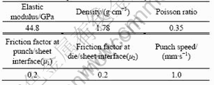
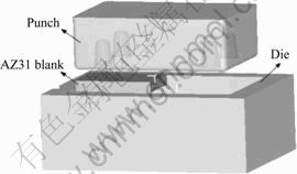
Fig.1 Finite element model of AZ31 alloy
2.2 Experiments
Press forging experiments were carried out to verify the results of FEM simulation results. Fig.2 shows the tools for press forging. The AZ31 sheets were cut by linear cutting machine into rectangle blanks with 20 mm in width, 30 mm in length and 2.0 mm in thickness. The clearance between the punch and die was 0.8 mm, i.e. sidewall thickness of the press forged part was 0.8 mm. The temperatures of the punch and the die were heated to 300-350 ℃ by cartridge heaters, and then the blank at room temperature was sandwiched between the high
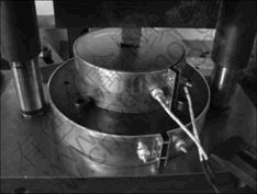
Fig.2 Press forging tools
temperature tools for 30 s and then it was detected to approximately 300 ℃[16]. Commercial solid lubricant MoS2 was used in the experiments. The punch stroke was 1.2 mm, i.e. the bottom thickness of the press forged part was 0.8 mm.
3 Results and discussion
3.1 Forming process
Fig.3 shows the experimental results and the forming process when the punch stroke reaches 0.6 mm, 0.9 mm and 1.2 mm. It is clearly seen that four bosses and sidewall are formed synchronously, the maximal sidewall height is located in the middle part of the long sides of the rectangular box and the height of the corner is minimal. Fig.3(b) also indicates that the top of the bosses is formed unevenly, and the regions of the cavities far away from the center are filled earlier than those close to the center. Fig.4 shows the variation of average height of boss (average value of maximal and minimal height of the boss) during press forging obtained
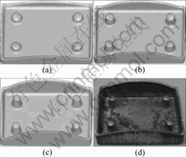
Fig.3 Forming process (FEM) and experiment results: (a) Stroke 0.6 mm; (b) Stroke 0.9 mm; (c) Stroke 1.2 mm; (d) Experiment
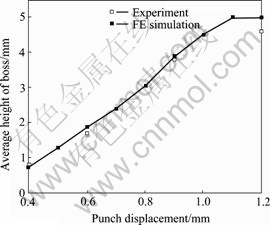
Fig.4 Boss height comparison between FE and experimental results
from FE simulation and experiments. It is clearly seen that FE results accord well with the experimental results before the punch stroke reaches 0.9 mm, but the final boss height in the experiment is 4.6 mm, which is less than that predicted from the FE simulation (5 mm). The reason is that there is no vent in the punch cavity and the punch cavity is airtight during press forging, so the metal cannot fill the cavity completely.
3.2 Effect of friction factor on forming uniformity of boss and sidewall
To investigate the effects of friction on boss forming, various values of friction factors (0.2, 0.4 and 0.7) were assigned to both the punch-sheet interface(μ1) and die- sheet interface(μ2) with the other process parameters remaining the same. Fig.5 shows the effect of friction factors on velocity field distribution when the punch stroke reaches 0.6 mm. It is seen that when the friction factor of tool/sheet interface is 0.2, as shown in Fig.5(a), the boss is formed unevenly. This is caused by the fast outward flow of metal. When the friction factor at die/sheet interface increases, as shown in Fig.5(b), the velocity difference of filling cavity is reduced and the metal flow pattern of boss forming gets improved. Fig.6(a) shows the effects of friction factor on average height of the boss and the height difference of the sidewall. In Fig.6(a), curves C and D indicate that the increase in the friction factor can enhance the efficiency
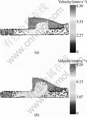
Fig.5 Effect of friction factor on velocity field at punch stroke of 0.6 mm: (a) μ1=0.2, μ2=0.2; (b) μ1=0.2, μ2=0.7
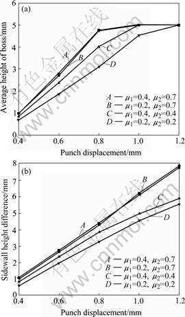
Fig.6 Effects of friction factor on press forging by FE simulation: (a) Effect on average height of boss; (b) Effect on sidewall height difference
of boss formation, and curves A and B, B and D show that die/sheet interface has much significant effect on improving boss forming efficiency. Fig.6(b) indicates that the height difference of the sidewall increases with the increase of the friction factor and that the die/sheet interface also shows more important influence on sidewall height difference.
3.3 Effect of sidewall thickness on boss forming and load
The effect of sidewall thickness(t) on boss forming is shown in Fig.7(a). It can be seen that the decrease in the thickness of the sidewall can enhance the efficiency of boss formation.
The reason is that the decrease in sidewall thickness increases the resistance of metal flow towards the sidewall, and no much metal flows quickly outward to form the sidewall, which makes the metal flow into the cavities easier. Fig.7(b) shows variations of forming load with different sidewall thickness, 0.6 mm, 0.8 mm and 1.0 mm. It is seen that the punch load increases with the decrease of the sidewall thickness.
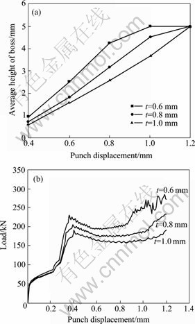
Fig.7 Effects of sidewall thickness on press forging by FE simulation: (a) Effect on average height of boss; (b) Effect on punch load
4 Conclusions
1) Press forging process can be used to synchronously form the bosses and sidewall of 3C products with magnesium alloy AZ31 sheets. The bosses are formed unevenly and the sidewall heights of the rectangular box are not uniform.
2) To improve the metal flow pattern and forming efficiency of the bosses, the friction factor at die/sheet interface should be larger than that at punch/sheet interface, but this lubrication method reduces the uniformity of the sidewall height.
3) The decrease in sidewall thickness enhances the efficiency of boss formation, whereas the punch load increases in the same situation.
References
[1] HARTLEY P, PILLINGER I. Numerical simulation of the forging process [J]. Comput Methods Appl Mech Engrg, 2006, 195(48/49): 6676-6690.
[2] KIM H, YAGI T, YAMANAKA M. FE simulation as a must tool in cold/warm forging process and tool design [J]. Journal of Material Processing Technology, 2000, 98(2): 143-149.
[3] OH S I, WU W T, ARIMOTO K. Recent developments in process simulation for bulk forming process [J]. Journal of Material Processing Technology, 2001, 111(1/3): 2-9.
[4] SHAN De-bin, XU Wen-chen, SI Chang-hao, LU Yan. Research on local loading method for an aluminum-alloy hatch with cross ribs and thin webs [J]. Journal of Material Processing Technology, 2007, 187/188: 480-485.
[5] WANG Guang-chun, ZHAO Guo-qun, XIA Shi-sheng, LUAN Yi-guo. Numerical and experimental study on new cold precision forging technique of spur gears [J]. Trans Nonferrous Met Soc China, 2003, 13(4): 798-802.
[6] LIM S C V, YONG M S. Plane-strain forging of wrought magnesium alloy AZ31 [J]. Journal of Material Processing Technology, 2006, 171(3): 393-398.
[7] L? Cheng, ZHANG Li-wen. Numerical simulation on forging process of TC4 alloy mounting parts [J]. Trans Nonferrous Met Soc China, 2006, 16(6): 1386-1390.
[8] WANG Xin-yun, WU You-sheng, XIA Ju-chen, HU Guo-an. FE simulation and process analysis on forming of aluminum alloy multi-layer cylinder parts with flow control forming [J]. Trans Nonferrous Met Soc China, 2005, 15(2): 452-456.
[9] HWANG J K, SOHN K Y, KIM H, KANG D M. CAE application to press forging of magnesium alloys [J]. Material Science Forum, 2003, 419/422: 371-376.
[10] HWANG J K, SOHN K Y, KANG D M, SHIN Y S. Finite element analysis of press forging process of AZ31 sheet [J]. Material Science Forum, 2005, 488/489: 457-460.
[11] CHEN F K, HUANG T B, WANG S J. A study of flow-through phenomenon in the press forging of magnesium alloy sheets [J]. Journal of Material Processing Technology, 2007, 187/188: 770-774.
[12] MURAKAMI H, SASAKI B, YONEOKA S, OHTAKE N, YASUHARA T. Method for preventing dimple defects on light sheet metal in boss forming [J]. Journal of the JSTP, 2007, 48(555): 293-297.
[13] CHEN F K, HUANG T B, CHEN S G. Embossment formation in press forging of AZ31 magnesium alloy sheets [J]. Int J Adv Manuf Technol, 2007, 32(3/4): 272-279.
[14] CHEN S J, CHEN F K. A study of press forging process of laser diode [J]. Forging, 2002, 11(4): 11-20. (in Chinese)
[15] ZHANG Shi-hong, LI Z G, XU Y C, REN L M, WANG Z T, ZHOU L X. Press forging of magnesium alloy AZ31 sheet [J]. Material Science Forum, 2007, 539/543: 1753-1758.
[16] MATSUMOTO R, OSAKADA K. Development of warm forging method for magnesium alloy [J]. Materials Transactions, 2004, 45(9): 2838-2844.
(Edited by ZHAO Jun)
Corresponding author: ZHANG Shi-hong; Tel: +86-24-83978266; E-mail: shzhang@imr.ac.cn

