
Shear band formation in shaped rheocast aluminium component at various plunger velocities
M. BLADH1, M. WESS?N2, A. K. DAHLE3
1. Swerea SWECAST AB, Box 2033, 550 02 J?nk?ping, Sweden;
2. Materials and Manufacturing-Casting, School of Engineering, J?nk?ping University,
551 11 J?nk?ping, Sweden;
3. Materials Engineering, The University of Queensland, Brisbane Queensland 4072, Australia
Received 13 May 2010; accepted 25 June 2010
Abstract: Significant progress has been made in recent years in understanding and modelling the rheology of semi-solid metals. These models show the effects of the microstructure in terms of size and morphology of globules on the material response. More recently it has been shown that semi-solid metals can behave as compacted granular materials such as sand. A particular signature of such deformation is that the deformation becomes concentrated into shear bands which are 10-20 grains wide. Such bands have also been observed in a range of cast products. Recently, it has been clearly shown that shear bands in high pressure die cast (HPDC) products are also the results of Reynolds dilatancy. Shear bands are also known to be a common feature in semi-solid metal products. The segregation banding in semi-solid metal (SSM) material and its dependence of plunger velocity were investigated. Shaped castings were made with the RHEOMETAL? process with a range of different plunger velocities. The microstructural characteristics were investigated, with a particular emphasis on shear bands. It is shown that ingate velocities influence the location and characteristics of the shear bands.
Key words: rheocasting; shear bands; segregation; Al-alloys; RHEOMETAL?
1 Introduction
High pressure die casting (HPDC) is one of the major processes used to make cast products for the automotive industry. Furthermore, when being used to make semi-solid metal (SSM) castings, the HPDC process has several advantages compared with conventional casting processes, such as reduced porosity and improved mechanical properties. In ordinary HPDC products it is common to observe positive macro- segregation of solute concentrated in what is known as defect bands. These bands follow the contour of the casting surface, usually of near-eutectic composition and may also contain porosity and/or cracks.
GOURLAY et al[1-3] studied the formation of these defect bands and found that they contain a larger fraction of Al-Si eutectic than the surroundings. Further studies by LAUKLI et al[4-5] and GOURLAY et al[6-7], and later OTARAWANNA et al[8-12] showed that partially solidified eqiaxed alloys can exhibit the characteristics of a cohesionless compacted granular material, such as volumetric response to shear, known as Reynolds’ dilatancy. Furthermore, research in the area of granular materials[10] pointed to a specific relationship between band thickness and grain size, i.e. the bands are 10-20 grains wide. This relationship is seen in controlled rheology experiments on partially solidified alloys as well.
Still today, there are different opinions on how these defect bands form during solidification in HPDC process. CAO et al[13] proposed two different mechanisms for the formation of defect bands, where one is dependent on the presence of externally solidified crystals (ESC). GOURLAY et al[1] on the other hand showed that ESC has no direct involvement in the mechanism of band formation, but the presence of ESC may indirectly influence its formation. The SSM HPDC processes are more different than regular HPDC process in that piston velocities are much slower, due to the high viscosity of the slurry. Also, the slurry consists of globular pre- solidified crystals, instead of equiaxed dendrites. This would be expected to have an effect on the formation of the defect bands, and also to a shift of the coherency point of the alloy. To obtain a more sound material and to increase the mechanical properties of the component, it is therefore important to investigate these bands further.
In the present study, HPDC process parameters are coupled with microstructure and investigated with respect to defect banding. The process parameter changed is the piston velocity during the second phase.
The characteristics of the microstructure are then investigated and discussed with respect to band thickness and location in the component.
2 Experimental
In this study, a commercial component manufactured by the RHEOMETAL? process was used to investigate the appearance of defect bands in the microstructure of a high-pressure die cast component. For the slurry preparation, a commercial RHEOMETAL? station was used in combination with a Frech 700 t cold chamber die casting machine for casting the component. Further information about the RHEOMETAL? process can be found elsewhere[13]. The slurry was prepared to a solid fraction of approximately 30%. The shot sleeve diameter was 80 mm and its length was 480 mm and the fill fraction was 25%.
The chemical composition of the alloy in this work is shown in Table 1. The samples were sectioned at fixed positions (see Fig.1), and prepared using standard metallographic techniques. A total of 7 samples were investigated at 3 positions each. Position 1 was examined parallel to the slurry bulk flow direction. Positions 2 and 3 were examined perpendicular to the slurry bulk flow direction. The casting from trial 3 was investigated in greater detail and the study was extended to six positions. All of them were sectioned perpendicular to the bulk flow. An optical microscope, LOM (Leica MEF4A and Leica M205C), was used to characterise the microstructure and to examine the influence of different piston velocities. To enhance the microstructure, the samples were etched in the modified Murakami etchant (60 mL H2O+10g NaOH+5g K3Fe(CN)6). Scanning electron microscopy (SEM) (Hitachi VP-SEM, S-3700N) was used in combination with energy-dispersive X-ray spectroscopy (EDX), to perform composition mapping.
Table 1 Chemical composition of alloy (mass fraction, %)
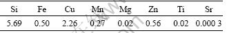
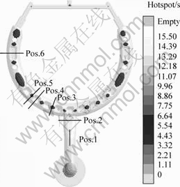
Fig.1 Component marked with positions, 1-6, examined for microstructure analyses and hot spot regions from simulation
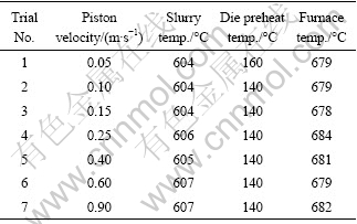
The piston velocity varied from 0.05 m/s to 0.9 m/s (same for 1st and 2nd phase). Table 2 shows the parameters associated with the test run. To ensure a steady-state operating environment, at least 20 samples were cast for each piston velocity.
Table 2 Shot parameters for trials
3 Results and discussion
Fig.2 shows typical images from three different piston velocities. Images marked with a arrow, symbolise the bulk flow direction. The lighter areas represent the eutectic phase, Al-12%Si, and the darker areas in the samples show the primary phase, Al. The white spots are small pores, mainly located in the hot spot area. None of the pores appear to be concentrated within the band, which is usually the case for HPDC and Mg-alloys, as reported in previous research[10].
It can be seen that the piston velocity has an influence on the location and number of segregation bands in the component. Previous work[10-11] on SSM and HPDC has shown banding in thixomoulded material. This implies that strain localisation occurs even in SSM casting. It is found that the bands are much narrower than ten primary globules thickness, suggesting a different mechanism for band formation.
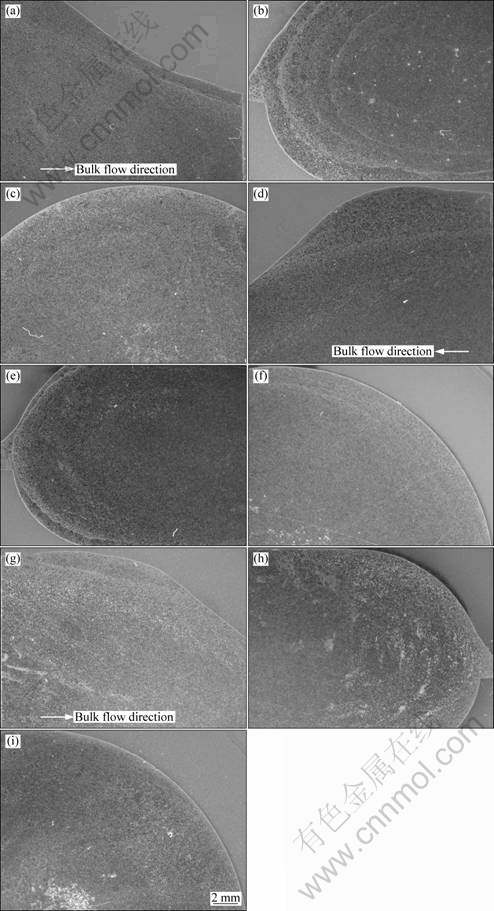
Fig.2 Typical etched optical images for three different piston velocities: (a) Sample 1, Pos.1, 0.05 m/s; (b) Sample 1, Pos.2, 0.15 m/s; (c) Sample 1, Pos.3, 0.60 m/s; (d) Sample 3, Pos.1, 0.05 m/s; (e) Sample 3, Pos.2, 0.15 m/s; (f) Sample 3, Pos.3, 0.60 m/s; (g) Sample 6, Pos.1, 0.05 m/s; (h) Sample 6, Pos.2, 0.15 m/s; (i) Sample 6, Pos.3, 0.10 m/s
An earlier study[14] using the RHEOMETAL process has shown that a piston velocity of 0.15 m/s gave the best filling and least amount of pores. To get a broader view, three more sections, positions 4-6, were polished and examined in this study, as shown in Fig.3. It is evident that shear banding is present in all sections. Positions 4 and 6 have about 30% decrease in cross section area, which results in an increase in bulk flow velocity. However, there is no clear difference in either position or width of the bands in comparison with positions 3 and 5 in Fig.3. As a result, in this study, it appears that the internal flow velocity change has little influence on the band position. However, different piston velocities seem to have an effect on the band positions as previously shown in Fig.2. In this study, the very slow piston velocities used in trial 1 could have an impact on the HPDC machine’s ability to function normally. At these very low velocities, the machine was operated unevenly, and could therefore be the origin of the multi layered band observed in Fig.2.
Fig.4 shows typical images from optical microscopy. Three areas are displayed; 1) outside the band, 2) band and 3) inside band. Area 1 is closest to the surface and experiences more rapid cooling than the inner regions, which can be seen in the mixture of globular grains and rosette shaped and/or dendritic grains, with the latter having formed during the rapid “quenching” of the liquid in the slurry. The centre part, area 3 in Fig.4, is densely packed with primary globules. In comparison with area 1 the globules are slightly coarser and significantly bigger than the few globules present in the band 2. The band 2 consists of a narrow shear band containing a high volume fraction of eutectic.
Small globular particles should result in a narrower band due to the smaller distances between the particles, compared with coarse equiaxed crystals, which need more space to move around each other. Therefore, they give intergranular liquid more space and subsequently, more solute to segregate during shearing. LUO et al[15] presents mechanical analyses of semi-solid metals, which indicate that under shear deformation SSM can appear as shear thinning if the grain boundary migrates inhomogeneously, due to different expansion of transition liquid layers. If these transition liquid layers are broken, and a flood current is developed rather than retains the adhesive liquid films, then the SSM behaves as shear thickening. If these narrow bands in SSM are formed under different mechanisms, as proposed by GOURLAY et al[11], it is possible that shear thickening liquid flooding is observed in SSM HPDC.
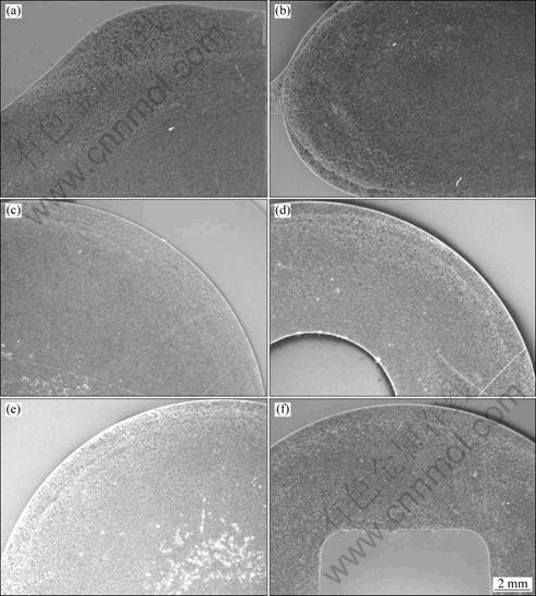
Fig.3 Typical etched optical images within trial 3 for piston velocity of 0.15 m/s: (a) Sample 3, Pos.1; (b) Sample 3, Pos.2; (c) Sample 3, Pos.3; (d) Sample 3, Pos.4; (e) Sample 3, Pos.5; (f) Sample 3, Pos.6
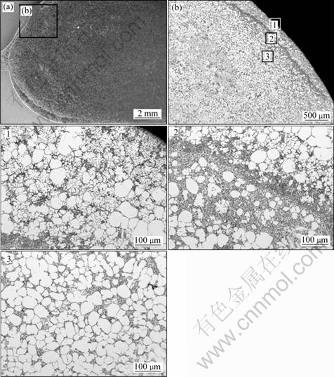
Fig.4 Etched images from trial 3 position 2, at piston velocity of 0.15 m/s, showing typical microstructure in area 1, 2 and 3
Generally, it is observed that the intermetallic phases are more common and smaller in the band region. OTARAWANNA et al[10] have also observed this phenomenon in their study of HPDC material. They found that the intermetallic phases were coarser within the bands. In the current samples, small Cu-bearing intermetallics are concentrated in the band, whereas Fe- and Mn-bearing intermetallics are evenly distributed in the microstructure and equal in size as seen in the EDX-mapping images in Fig.5. SEM images in Figs.6 and 7 show the band region in both SE and BSE detector. Lighter areas indicate intermetallic phases, grey areas are the eutectic Al-Si and black areas are the pro-eutectic Al.
Areas 1 and 3 in Fig.4 show that the solid fraction of globules is quite different from the initial one. The slurry is prepared to approximately 30% solid fraction of globules; still area 1 generally has lower solid fraction than the initial, whereas area 3 generally has higher solid fraction of globules.
According to previous research findings by LAUKLI et al[4], during shearing in semi-solid castings the ESC migrated towards the centre of flow due to a combination of lift forces and wall effects. LAUKLI et al also found that solid fraction affected the distribution of ESC. At lower solid fraction the centre region was strongly compacted whereas for higher solid fraction the region of migrating ESC was larger and closer to the surface but not compacted. In this study with 30% solid fraction, it is seen that smaller globules are more densely compacted in the centre compared with slightly larger globules in a sparsely compacted surface.
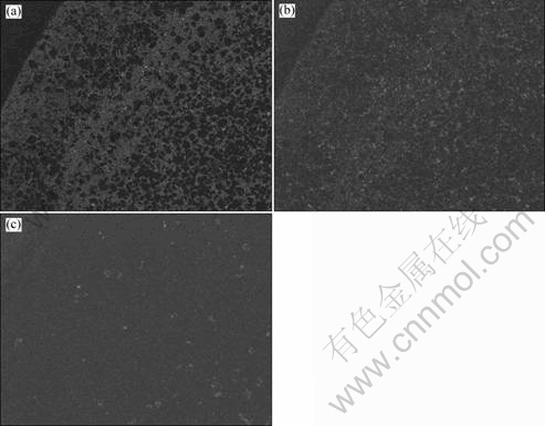
Fig.5 SEM image showing EDX-mapping with regards to Si distribution (a), Cu distribution (b) and Mn distribution (c) with more intense colour indicating increase in concentration
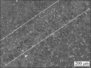
Fig.6 SEM BSE image covering a band, diagonally over image inside dotted lines (Dark areas: primary Al, grey areas: Al-Si eutectic; white dots: Cu-rich intermetallic phases)
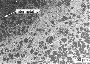
Fig.7 SEM SE image displaying band, light area cross diagonal
4 Conclusions
1) At slower phase 1 filling velocities, multiple defect bands were observed in the components.
2) No porosity was found in the defect band, which only contained positive macrosegregation of eutectic.
3) No difference in band position was obvious.
4) Intermetallic phases are evenly distributed, but smaller in band.
Acknowledgements
The author (M. BLADH) acknowledges the Swedish Agency for Innovation System (VINNOVA) and Swerea SWECAST (the Swedish foundry association) for financial support.
References
[1] GOURLAY C M, LAUKLI H I, DAHLE A K. Defect band characteristics in Mg-Al and Al-Si high-pressure die castings [J]. Metallurgical and Materials Transactions A, 2007, 38: 1833-1844.
[2] GOURLAY C M, DAHLE A K. Dilitant shear bands in solidifying metals [J]. Nature, 2007, 445: 70-73.
[3] GOURLAY C M, LAUKLI H I, DAHLE A E. Segregation band formation in Al-Si die castings [J]. Metallurgical and Materials Transactions A, 2004, 35: 2881-2891.
[4] LAUKLI H I, GOURLAY C M, DAHLE A K. Migration of crystals during the filling of semi-solid castings [J]. Metallurgical and Materials Transactions A, 2005, 36: 805-818.
[5] LAUKLI H I, GOURLAY C M, DAHLE A K, LOHNE O. Effects of Si content on defect band formation in hypoeutectic Al-Si die castings [J]. Materials Science and Engineering A, 2005, 413/414: 92-97.
[6] GOURLAY C M, OTARAWANNA S, LAUKLI H I, DAHLE A K. An overview of defect bands in high pressure die castings [J]. Die Castings Engineer, 2008, 52(1): 32-35.
[7] GOURLAY C M, MEYLAN B, DAHLE A K. Shear mechanisms at 0-50% solid during equiaxed dendritic solidification of an AZ91 magnesium alloy [J]. Acta Materialia, 2008, 56: 3403-3413.
[8] OTARAWANNA S, GOURLAY C M, LAUKLI H I, DAHLE A K. The influence of intensification pressure on the gate microstructure of AlSi3MgMn high pressure die castings [J]. Materials Science Forum, 2009, 618/619: 607-610.
[9] OTARAWANNA S, GOURLAY C M, LAUKLI H I, DAHLE A K. Microstructure formation in AlSi4MgMn and AlMg5Si2Mn high-pressure die castings [J]. Metallurgical and Materials Transactions A, 2009, 40: 1645-1659.
[10] OTARAWANNA S, GOURLAY C M, LAUKLI H I, DAHLE A K. The thickness of defect bands in high-pressure die castings [J]. Materials Characterization, 2009, 60(12): 1432-1441.
[11] GOURLAY C M, OTARAWANNA S, MEYLAND B, DAHLE A K. Reynolds’ dilatancy and shear bands in semi-solid alloys [J]. Solid State Phenomena, 2008, 141/142/143: 337-342.
[12] OTARAWANNA S, GOURLAY C M, LAUKLI H I, DAHLE A K. Agglomeration and bending of equiaxed crystals during solidification of hypoeutectic Al and Mg alloys [J]. Acta Materialia, 2009, 58(1): 261-271.
[13] CAO H, WESS?N M. Characteristics of microstructure and banded defects in die cast AM50 magnesium components [J]. International Journal of Cast Metals Research, 2005, 18(6):377-384.
[14] CAO H, WESS?N M, GRANATH O. Effect of injection velocity on porosity formation in a rheocast Al component using RHEOMETAL? process [J]. International Journal of Cast Metals Research, 2010, 23(3): 158-163.
[15] LUO S, CHEN Q, GAO X. Mechanical analysis of semi-solid metals shear deformation during compression [J]. Solid State Phenomena, 2008, 141/142/143: 439-443.
(Edited by YANG Bing)
Corresponding author: M. BLADH; E-mail: madeleine.bladh@swerea.se
DOI: 10.1016/S1003-6326(09)60369-1

