
Effects of Dy on cyclic oxidation resistance of NiAl alloy
GUO Hong-bo(���鲨)1, 2, WANG Xiao-yan(������)1, 2, LI Ji(�� ��)3,
WANG Shi-xing(������)1, 2, GONG Sheng-kai(������)1, 2
1. Department of Materials Science and Engineering, Beijing University of Aeronautics and Astronautics,
Beijing 100083, China;
2. Beijing Key Laboratory for Advanced Functional Materials and Thin Film Technology,
Beijing University of Aeronautics and Astronautics, Beijing 100083, China;
3. Shenyang Liming Aero-Engine Group Corporation, Shenyang 110043, China
Received 27 May 2008; accepted 21 October 2008
Abstract: The NiAl alloys modified by reactive element(RE), dysprosium(Dy), were produced by arc melting. The microstructures of the modified alloys were investigated by field emission-scanning electron microscope(FE-SEM) equipped with energy dispersive spectroscope(EDS) and back scatter detector. Cyclic oxidation tests at 1 200 �� were conducted to assess the cyclic oxidation performance of the alloys. The Dy dopant prevents the surface rumpling of the oxide scale and the formation of cavities beneath the oxide scale. The pegs consisting of Dy-rich oxide inclusion core and an outer alumina sheath develop deeply in the alloy and improve the oxide scale adhesion. 0.05%-0.1% (molar fraction) Dy dramatically improves the cyclic oxidation resistance of the NiAl alloy. Too high concentration of Dy is deleterious because of the fast oxidation rate caused by severe internal oxidation.
Key words: NiAl; reactive element; dysprosium(Dy); oxidation; adhesion
1 Introduction
In order to protect hot-section components in gas turbine engines, thermal barrier coatings(TBCs) consisting of thermally insulating ceramic top coat and oxidation-resistant metallic bond coat are widely applied[1-2]. Oxidation of the bond coat is a primary failure mechanism of TBCs. Cracks often occur along the metal/oxide interface, leading to large-scale buckling and spallation[3-5]. The conventional bond coat is MCrAlY, but it couldn��t be used over 1 150 �� because oxidation of the bond coat over this temperature results in accelerated thermally grown oxide(TGO) thickening that tends to cause premature spallation of TBC by cracking in TGO. As the turbine-inlet temperatures continue to rise it is likely that NiAl will attract increasing attention because of its high melting point and excellent oxidation resistance[6-7]. For temperatures approaching 1 200�� the aluminide provides a superior oxidation resistance due to the continuous formation of protective Al2O3 scale. However, the oxide scales formed on NiAl spall severely due to the formation of cavities and scales rumpling. In order to solve this problem, addition of some elements such as reactive elements to NiAl is widely studied. It has been known that the addition of Zr, Y, Hf and their oxide dispersions are beneficial to enhancing the adhesion of oxides scale at elevated temperatures[7-11]. One of the mechanisms is that the reactive elements can suppress sulfur detrimental effect, that is, sulfur in NiAl promotes the formation of cavities under the oxide scale.
Rare earth element Dy is also a reactive element. Dy improved the oxidation resistance of NiAl-31Cr-3Mo superalloy via the formation of continuous sole protective Al2O3 scale[12-13]. Dy may have similar effects like Hf, Zr, Y that can decrease the detrimental effect of sulfur and modify the adhesion of oxide scale. ZHANG et al[12-13] have investigated the effects of Dy on oxidation performance and mechanical properties of NiAl intermetallic compounds. The addition of Dy improved not only cyclic oxidation resistance but also mechanical properties. However, as a potential high temperature protective coating or as the bond coat in TBC, NiAlDy coating has been less reported.
In this work, the Dy doped NiAl intermetallic compounds are produced by arc-melting. The effects of Dy additions on the microstructures and cyclic oxidation performances of the compounds are investigated, with the aim of exploiting the NiAl as a high-temperature protective coating or the bond coat in advanced TBC.
2 Experimental
NiAl alloys with different Dy contents were used in this work. The designed compositions of the alloys were Ni-50Al, Ni-49.95Al-0.05Dy, Ni-49.9Al-0.1Dy, Ni- 49.5Al-0.5Dy (molar fraction, %), respectively. Metals of Ni, Al and Dy with high purity (��99.999%) were used as starting materials. The alloy buttons were produced in argon atmosphere by arc melting. The specimens for oxidation testing were cut from the alloy buttons into 10 mm��10 mm��3 mm. Then the surfaces of the specimens were ground by SiC paper of 800 grit. Subsequently, the specimens were ultrasonically cleaned in alcohol and acetone.
Cyclic oxidation tests of the NiAl alloys were conducted at 1 200 ��. The alloy specimens were held in alumina crucibles and heated in air furnace to 1 200 ��. After 1 h thermal exposure, the specimens were cooled down to ambient temperature and the mass gains of the crucibles with the specimens were recorded by an electronic balance (Sartorious BS 224S, Germany) with a precision of 0.1 mg. Also, the mass changes of the specimen only were recorded by the balance.
The surface morphologies and cross-section microstructures of the specimens after cyclic oxidation were characterized by optical microscope(OM), scanning electron microscope(SEM) and field emission scanning electron microscope(FE-SEM) equipped with energy dispersive spectroscope(EDS) and back scattering electron(BSE) detector. For cross-section observation, the specimens were embedded in resin and then sectioned, ground and finely polished.
3 Results and discussion
3.1 Microstructures of Dy doped NiAl alloys
Figs.1(a)-(d) show the optical micrographs of the cross-sections of the NiAl alloys with different Dy contents, respectively. For the undoped NiAl, the grain size is in the level of 1 mm. In contrast to this, the Dy doped NiAl alloys show apparent reduction in the grain size. Especially for the 0.5% Dy doped NiAl, the grain size is reduced by more than 4 times. This indicates that the addition of Dy leads to the refinement of NiAl grains. Also, it can be observed that some black phases are distributed in the grains or along the grain boundaries. Fig.2 shows the back scatter scanning electron micrograph of the 0.5% Dy doped NiAl. Dy is mainly distributed along grain boundaries as Dy-rich compound and in grains as Dy-rich precipitates. The precipitates at the grain boundaries and within the grains correspond to those black phases observed in the optical micrograph. The precipitate at the grain boundary is identified to be DyNi2Al3 phase by the energy dispersive spectroscopy (EDS) analysis of field emission scanning electron microscopy(FE-SEM), while the precipitate within the grains consist of two phases: one is DyNi2Al3 phase and the other is DyNiAl phase.
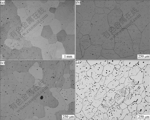
Fig.1 Optical micrographs(OM) of cross-sections of NiAl alloys: (a) NiAl; (b) NiAl-0.05%Dy; (c) NiAl-0.1%Dy; (d) NiAl-0.5%Dy
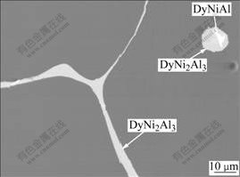
Fig.2 Field emission scanning electron microscopy(FE-SEM) micrograph of NiAl-0.5Dy alloy
3.2 Cyclic oxidation of NiAl alloys at 1 200 ��
Fig.3(a) shows the mass gains of the NiAl alloys together with alumina crucibles during 1 h cyclic oxidation at 1 200 ��. The NiAl, NiAl-0.05%Dy and NiAl-0.1%Dy alloys exhibit very similar mass gains during cyclic oxidation. After 100 h thermal exposure, the mass gain is around 1 mg/cm2. The NiAl-0.5%Dy alloy has a much higher mass gain than other NiAl alloys, which is nearly double that of the NiAl alloys with lower Dy contents.
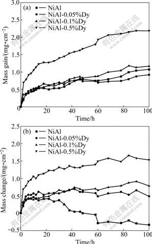
Fig.3 Mass gains of NiAl specimens with alumina crucible (a) and mass changes of NiAl specimens (b) during 1 h cyclic oxidation at 1 200 ��
Fig.3(b) shows the mass changes of the NiAl alloys during the cyclic oxidation. An abrupt mass loss is observed for the undoped NiAl alloy after about 30 cycles, indicating that spallation of oxide scale occurs. For the Dy doped alloys, apparent mass changes haven��t happened during 100 cycles. It can be inferred that the additions of Dy effectively improve the adhesion of the oxide scale with the underlying alloy. However, it should be noted that the 0.5% Dy doping leads to so fast oxidation rate despite that an apparent mass loss is avoided during cyclic oxidation due to the addition of Dy. In contrast to this, a good resistance to cyclic oxidation is achieved in both the 0.05% Dy and 0.1% Dy doped alloys.
Figs.4(a)-(d) show the BSE images of the surfaces of the NiAl alloys after cyclic oxidation at 1 200 ��. The dark areas indicate Al2O3 regions, while the light areas indicate NiAl regions where the scales have already spalled. Also, for the Dy doped alloys, some light dots within the grains and at grain boundaries denote the Dy-rich oxides. It can be observed that spallation of large bulks of oxides occurs on the surface of the undoped- NiAl alloy after 50 cycles, as shown in Fig.4(a). A little spallation can be seen in Fig.4(b) and less spallation is observed in Fig.4(c). It can be concluded that the addition of 0.05%-0.1% Dy to NiAl can effectively improve the adhesion of oxide scale. For the NiAl- 0.5%Dy alloy, the spallation areas increase a little as compared with the NiAl-0.1%Dy alloy. This suggests that the addition of 0.5% Dy may be detrimental to the oxidation performance of the alloy because too high content of Dy could accelerate the oxidation of the alloy and lead to a thick oxide scale. As a result, thermal stresses increase and finally cause the spallation of the oxide scale.
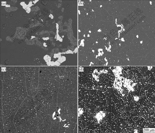
Fig.4 Back scatter electron(BSE) images of surface of NiAl alloys after cyclic oxidation at 1 200 ��: (a) Undoped NiAl, 50 h; (b) NiAl-0.05%Dy, 100 h; (c) NiAl-0.1%Dy, 100 h; (d) NiAl-0.5%Dy, 100 h
Figs.5(a) and (b) show the BSE images of the cross-sections of the NiAl and NiAl-0.05%Dy alloys after cyclic oxidation at 1 200 ��. For the undoped NiAl alloy (shown in Fig.5(a)), an alumina scale (black phase) about 2 ?m in thickness is formed after 2 cycles. Besides, many cavities present beneath the oxide scale. Due to the presence of those cavities, the adhesion of the oxide scale is significantly degraded[14]. The surface rumpling of NiAl alloy is evidently seen after 2 oxidation cycles in Fig.5(a). It is obvious that spallation of the oxide scale would occur after a few cycles by a so-called ��buckling mechanism��. This indicates that the undoped NiAl exhibits a very poor cyclic oxidation performance at 1 200 ��. There are usually two main reasons for the disadvantage of the alloy. One is that the indigenous sulfur existing in NiAl alloy at 10-6 level tends to segregate to the Al2O3/alloy interface during oxidation to weaken the bonding and promote interfacial void formation, hence reducing the adhesion of the oxide scale[15-16]. The other is the mismatch of thermal expansion between the Al2O3 and NiAl, resulting in high- level thermal stresses that are large enough to cause cracking of the oxide scale during cooling stage.
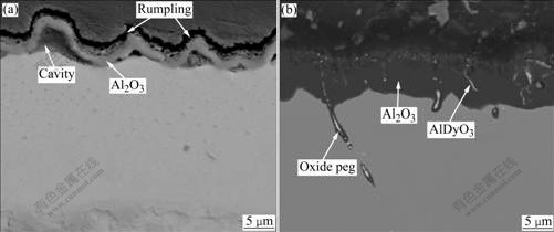
Fig.5 Back scatter electron(BSE) images of cross-sections of NiAl alloy after 2 cycles (a) and NiAl-0.05%Dy alloy after 100 cycle (b) at 1 200 ��
Fig.5(b) shows the BSE image of the cross-section of the NiAl-0.05%Dy alloy after 100 cycles. The Al2O3 scale (black phase) is still intimately bonded to the alloy although its thickness approaches 10 mm, suggesting a strong scale adhesion. Some white phases are present both in the oxide scale and at the grain boundary. These white phases are identified by EDS analysis of field emission scanning electron microscopy(FE-SEM) to be AlDyO3 phase. The AlDyO3 phase at the grain boundary works as ��oxide pegs�� to improve the adherence of the oxide scale. In contrast to the undoped alloy, little rumpling and few interfacial voids can be seen in the Dy doped alloy. This indicates that the addition of Dy effectively avoids surface rumpling and interfacial voids.
In summary, adding a reactive element, such as Dy, Hf and Y (mainly distributed at the grain boundaries), which has a high affinity for both oxygen and sulfur, can thus prevent the sulfur segregation and suppress the formation of interfacial voids (as shown in Fig.5(b)). Besides, along the alloy grain boundary, there are protrusions of secondary oxide inclusions called pegs which penetrate into the alloy substrate, as shown in Fig.5(b). The pegs consisting of Dy-rich oxide core and an outer alumina sheath play an important role in improving the adhesion by pegging in the substrate. The pegging effect has been proposed as one of the mechanisms with which reactive elements improve spallation resistance of NiAl[17]. Additionally, Dy distributing in the grains begins to diffuse outwards and is oxidized to form AlDyO3 phase during thermal exposure. The presence of the AlDyO3 phase could modify the mechanical properties of the oxide scale and balance the thermal expansion mismatch between the scale and the alloy.
Although Dy is substantially beneficial to NiAl oxidation resistance, too high concentration of Dy is negative to oxidation resistance. It has been proved that reactive element effect cannot work when the concentration of reactive element is over 0.1% (molar fraction)[18]. In this work, the oxidation rate of the NiAl-0.5%Dy alloy is much faster than the other alloys (as shown in Fig.3(a)) as a result of severe internal oxidation.
4 Conclusions
1) For the Dy doped NiAl alloys, Dy mainly segregates to grain boundaries and precipitates in grains as Dy-rich DyNi2Al3. The addition of Dy results in the refinement of the NiAl grains.
2) The Dy doping prevents the surface rumpling of the oxide scale and the formation of cavities beneath the oxide scale. The pegs consisting of Dy-rich oxide inclusion core and an outer alumina sheath develop deeply in the alloy and improve the adhesion of the oxide scale.
3) 0.05%-0.1% (molar fraction) Dy remarkably improves the cyclic oxidation resistance of the NiAl alloy. But 0.5% Dy is deleterious because of the faster oxidation rate caused by severe internal oxidation.
References
[1] POMEROY M J. Coatings for gas turbine materials and long term stability issues [J]. Materials and Design, 2005, 26: 223-231.
[2] PADTURE N P, GELL M, JORDAN E H. Thermal barrier coatings for gas-turbine engine applications [J]. Science, 2002, 296: 280-284.
[3] RABIEI A, EVANS A G. Failure mechanisms associated with the thermally grown oxide in plasma-sprayed thermal barrier coatings [J]. Acta Material, 2000, 48(15): 3963-3976.
[4] WRIGHT P K, EVANS A G. Mechanisms governing the performance of thermal barrier coatings [J]. Current Opinion in Solid State and Materials Science, 1999, 4(3): 255-265.
[5] SPITSBERG I, MORE K. Effect of thermally grown oxide(TGO) microstructure on the durability of TBCs with PtNiAl diffusion bond coats [J]. Mater Sci Eng A, 2006, 417: 322-333.
[6] HAYNES J A, PINT B A, ZHANG Y, WRIGHT I G. Comparison of the cyclic oxidation behavior of ��-NiAl, ��-NiPtAl and �èC�á�NiPtAl coatings on various super alloys [J]. Surface and Coatings Technology, 2007, 202: 730-734.
[7] GUO Hong-bo, SUN Li-dong, LI He-fei, GONG Sheng-kai. High temperature oxidation behavior of hafnium modified NiAl bond coat in EB-PVD thermal barrier coating system [J]. Thin Solid Films, 2008, 516(16): 5732-5735.
[8] HAYNES J A, PINT B A, MORE K L, ZHANG Y, WRIGHT I G. Influence of sulfur, platinum, and hafnium on the oxidation behavior of CVD NiAl bond coatings [J]. Oxidation of Metals, 2002, 58(5/6): 513-544.
[9] PINT B A, WRIGHT I G, LEE W Y, ZHANG Y, PR��?NER K, ALEXANDER K B. Substrate and bond coat compositions: Factor affecting alumina scale adhesion [J]. Mater Sci Eng A, 1998, 245(2): 201-211.
[10] PINT B A, TRESKA M, HOBBST L W. The effect of various oxide dispersions on the phase composition and morphology of A12O3 scales grown on ��-NiA1 [J]. Oxidation of Metals, 1997, 47(1/2): 1-20.
[11] PINT B A. The role of chemical composition on the oxidation performance of aluminide coatings [J]. Surface and Coatings Technology, 2004, 188/189: 71-78.
[12] ZHANG Guang-ye, ZHANG Hua, GUO Jian-ting. Improvement of cyclic oxidation resistance of a NiAl-based alloy modified by Dy [J]. Surface and Coatings Technology, 2006, 201: 2270-2275.
[13] ZHANG Guang-ye, ZHANG Hua, WANG Zhen-sheng, GUO Jian-ting, ZHOU Lan-zhang. Oxidation behavior of NiAl-30.9Cr- 3Mo-0.1Dy alloy at high temperature [J]. Rare Metal Materials and Engineering, 2006, 35: 719-723.
[14] HOU P Y, PRIIMAK K. Interfacial segregation, pore formation, and scale adhesion on NiAl alloys [J]. Oxidation of Metals, 2005, 63 (1/2): 113-130.
[15] SMITH M A, FRAZIER W E, PREGGER B A. Effect of sulfur on the cyclic oxidation behavior of a single crystalline, nickel-base superalloy [J]. Mater Sci Eng A, 1995, 203: 388-398.
[16] SCHAEFFER J C, MURPHY W H, SMIALEK J L. The effect of surface condition and sulfur on the environmental resistance of airfoils [J]. Oxidation of Metals, 1995, 43(1/2): 1-23.
[17] MENNICKE C, HE M Y, CLARKE D R, SMITH J S. The role of secondary oxide inclusions (��peg��) on the spalling resistance of oxide films [J]. Acta Materialia, 2000, 48: 2941-2949.
[18] ZHANG Yong-gang, HAN Ya-fang, CHEN Guo-liang, GUO Jian-ting, WANG Xiao-jing, FENG Di. Structure intermetallics [M]. Beijing: National Defense Industry Publishing House, 2001: 453-457. (in Chinese)
Foundation item: Projects(50731001, 50771009) supported by the National Natural Science Foundation of China; Project(PCSIRT/IRT 0512) supported by the Program for Changjiang Scholars and Innovative Research Team in Chinese University
Corresponding author: GUO Hong-bo; Tel: +86-10-82317117; E-mail: guo.hongbo@buaa.edu.cn
DOI: 10.1016/S1003-6326(08)60426-4
(Edited by YANG Bing)

