
Mechanical properties of QFP micro-joints soldered with lead-free solders using diode laser soldering technology
HAN Zong-jie(韩宗杰)1, XUE Song-bai(薛松柏)1, WANG Jian-xin(王俭辛)1, ZHANG Xin(张 昕)1,
ZHANG Liang(张 亮)1, YU Sheng-lin(禹胜林)1, 2, WANG Hui(王 慧)1
1. College of Materials Science and Technology, Nanjing University of Aeronautics and Astronautics,
Nanjing 210016, China;
2. The 14th Research Institute, China Electronics Technology Group Corporation, Nanjing 210013, China
Received 22 October 2007; accepted 7 April 2008
Abstract: Soldering experiments of quad flat package(QFP) devices were carried out by means of diode laser soldering system with Sn-Ag-Cu and Sn-Cu-Ni lead-free solders, and competitive experiments were also carried out not only with Sn-Pb eutectic solders but also with infrared reflow soldering method. The results indicate that under the conditions of laser continuous scanning mode as well as the fixed laser soldering time, an optimal power exists, while the optimal mechanical properties of QFP micro-joints are gained. Mechanical properties of QFP micro-joints soldered with laser soldering system are better than those of QFP micro-joints soldered with IR reflow soldering method. Fracture morphologies of QFP micro-joints soldered with laser soldering system exhibit the characteristic of tough fracture, and homogeneous and fine dimples appear under the optimal laser output power.
Key words: quad flat package micro-joints; mechanical properties; lead-free solders; diode laser soldering
1 Introduction
Quad flat package(QFP) is one of the most common package types in surface mount technology(SMT) which is used in many large scale integration(LSI) and very large scale integration(VLSI)[1]. With the miniaturization of electronic productions, the lead pitch of QFP devices changes from 1, 0.8, 0.65 mm to 0.4 and 0.3 mm even much smaller pitch, and the traditional reflow soldering technologies often have difficulties, such as low mechanical properties of QFP micro-joints and bridging, which is a universal concern to soldering engineers. In recent years, many studies show that by means of laser soldering technology, mechanical properties of QFP micro-joints can be improved, and few defects exist [2-3].
Environmental regulations emerged worldwide have targeted the elimination of Pb because of the inherent toxicity of Pb[4-7], so Sn-Ag and Sn-Cu series lead-free solders have been developed and recommended as substitutes for Sn-Pb solders[6-12]. In automated soldering of printed circuited/wired board(PCB or PWB),
there are two basic methods: wave soldering and reflow soldering[13]. Lead-free soldering often becomes difficult because of the high melting points and bad wettability of the lead-free solders, and defect-free production must be achieved before lead-free soldering becomes more common[13].
Solderability of QFP devices was investigated when being soldered with Sn-Ag-Cu and Sn-Cu-Ni lead-free solders by means of diode laser soldering system and competitive experiments were also carried out not only with Sn-Pb eutectic solders but also with infrared reflow soldering method. Laser soldering technology illustrated a good prospect of application [14-16]. In this study, the advantages of laser soldering technology were investigated, which gives guides to practical application of this technology in the lead-free environments.
2 Experimental
2.1 Materials and equipment
TQFP100 device with the leads number of 100 is shown in Fig.1. In Sn-Ag-Cu lead-free solders, Ag content (mass fraction) was 3.00%, Cu content was 0.50%, the balance was Sn. In Sn-Cu-Ni lead-free solders, Cu content was 0.50%, Ni content was 0.050%, the balance was Sn. In Sn-Pb solders, Pb content was 37%, the balance was Sn. There were no-clean flux and FR-4 PCB boards.
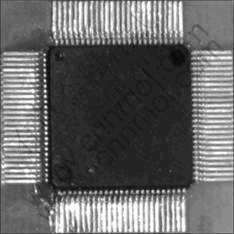
Fig.1 TQFP100 device with leads number of 100
Laser output wavelength of diode laser soldering system was 808 nm, in laser continuous scanning mode. Infrared reflow(IR) soldering oven was used for soldering QFP devices, as competitive experiments with laser soldering technology. Micro-joints tester was used for testing mechanical properties of QFP micro-joints. Scanning electron microscope(SEM) was used for studying fracture morphology of QFP micro-joints.
2.2 Methods
Soldering experiments of QFP devices were carried out with diode laser soldering system and IR reflow soldering oven respectively. As for laser soldering, laser output power and laser scanning speed were controlled by computer, and suitable parameters were selected according to actual demand. After soldering experiments, the mechanical properties of QFP micro-joints were tested by micro-joints tester, and fracture morphology of micro-joints was studied by SEM.
3 Results and discussion
3.1 Influence of laser output power on mechanical properties of QFP Sn-Ag-Cu micro-joints
TQFP100 devices were soldered on PCB with Sn-Ag-Cu lead-free solder, and laser scanning speed was 2 mm/s. The relationship between mechanical properties (maximum tensile forces) of micro-joints and laser output power is shown in Fig.2.
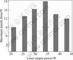
Fig.2 Relationship between laser output power and maximum tensile force of QFP Sn-Ag-Cu micro-joints
Under the conditions of laser continuous scanning mode as well as the fixed laser soldering time, maximum tensile force of QFP micro-joints increases gradually with the increase of laser output power. The maximum force of QFP micro-joints is gained when the laser output power increases to 34.1 W, which shows that the PCB is wetted adequately by molten Sn-Ag-Cu lead-free solder, and the best mechanical properties of micro-joints are gained at the same time.
3.2 Influence of laser output power on mechanical properties of QFP Sn-Cu-Ni micro-joints
TQFP100 devices were soldered on PCB with Sn-Cu-Ni lead-free solder, and the laser scanning speed was also 2 mm/s, then maximum forces of micro-joints were also tested by micro-joints tester. The relationship between maximum forces and laser output powers is shown in Fig.3.
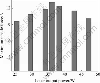
Fig.3 Relationship between laser output power and maximum tensile force of QFP Sn-Cu-Ni micro-joints
It can be seen from Fig.3 that the relation between maximum forces and laser output powers for Sn-Cu-Ni lead-free joints is the same as that for Sn-Ag-Cu lead-free joints. Maximum force of QFP micro-joints increases gradually with the increase of laser output power, and the optimal laser output power is 36.1 W.
The relation between maximum forces and laser output powers for Sn-Pb joints is also similar to that for Sn-Ag-Cu lead-free joints, and the optimal laser output power is 29.6 W.
Laser parameters are different when different solders are used. With the laser scanning speed fixed, the higher the melting point of the solder is, the larger the optimal laser output power is. The optimal laser power of Sn-Cu-Ni lead-free solder is larger than that of Sn-Ag-Cu lead-free solder and Sn-Pb solder, while the optimal laser power of Sn-Ag-Cu lead-free solder is larger than that of Sn-Pb solder.
3.3 Influence of soldering methods on mechanical properties and fracture morphology of QFP micro-joints
Table 1 lists the test results of mechanical properties of QFP micro-joints soldered by means of diode laser soldering system and IR reflow soldering method. IR reflow soldering temperature was 210 ℃ for Sn-Pb soldered QFP devices, while for Sn-Ag-Cu and Sn-Cu-Ni lead-free soldered QFP devices, IR reflow soldering temperature was 240 ℃. Laser scanning speed was fixed as 2 mm/s, and the laser output powers of Sn-Pb soldered QFP devices was 29.6 W, while the powers of Sn-Ag-Cu and Sn-Cu-Ni lead-free soldered QFP devices were 34.1 W and 36.1 W, respectively, which is related to melting points of three kinds of solders. The melting points of Sn-Pb, Sn-Ag-Cu and Sn-Cu-Ni are 183 ℃, 217 ℃ and 227-230 ℃, respectively. With the laser scanning speed fixed, the higher the melting point of solder is, the larger the optimal laser output power is.
Table 1 Maximum force of QFP micro-joints (N)
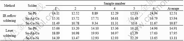
Table 1 shows that by means of the same soldering method, the mechanical properties of Sn-Ag-Cu lead-free micro-joints are better than those of Sn-Pb micro-joints. Although the mechanical properties of Sn-Cu-Ni lead-free micro-joints are poor, they are able to meet the demands of MIL-STD-883 Method 2011.7 Bond Strength.
Mechanical properties of QFP micro-joints soldered by laser soldering and IR reflow soldering, with Sn-Pb solder, Sn-Ag-Cu and Sn-Cu-Ni lead-free solders are shown in Fig.4. It is concluded that mechanical properties of QFP micro-joints soldered by laser soldering system are better than those soldered by IR reflow soldering methods, not only for Sn-Pb solder but also for Sn-Ag-Cu and Sn-Cu-Ni lead-free solders.
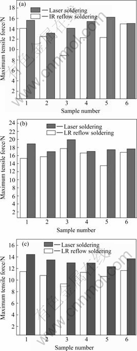
Fig.4 Tensile properties of QFP micro-joints soldered with two methods: (a) Sn-Pb micro-joints; (b) Sn-Ag-Cu micro-joints; (c) Sn-Cu-Ni micro-joints
IR reflow soldering method is a kind of integral heat soldering method, in which the entire assembly is passed through an oven. While an important advantage of laser soldering lies in the ability to direct the energy beam accurately and precisely onto a target area without heating the surrounding parts. The minimal rise in substrate temperature reduces mechanical stress and the rapid heating and cooling of the solder minimize the formation of intermetallic compounds that can cause brittleness and joint failure. Laser soldering is a non- contact process, and objects can be soldered in areas difficult to reach using conventional techniques. Laser soldering technology illustrates a good prospect of application.
Fracture morphologies of QFP Sn-Pb micro-joints soldered by two methods are shown in Fig.5. From Fig.5, it can be seen that fracture morphology of micro-joints soldered by IR reflow soldering method shows ligule pattern and dimples, which indicates toughness fracture and brittle fracture. Fracture morphology of laser soldered micro-joints shows homogeneous dimples, which indicates that the fracture type is toughness fracture, since dimples are of the typical characteristic of toughness fracture[17], and intense plastic deformation appears before fracture.
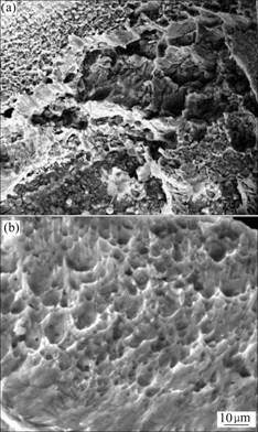
Fig.5 Fracture morphologies of QFP micro-joints soldered with Sn-Pb solder: (a) IR reflow soldering; (b) Laser soldering
The important characteristic of micro-porous aggregation fracture is the existence of dimple[17], which indicates that the intense plastic deformation happened in certain region of materials. The impurities or the second phase particles play an important role in the formation of dimple. Because the plastic deformation causes the contact surface between the second phase particle and the substrate material crack, thus forming dimple. Then the second phase particles are detectable among dimple, therefore, the micro-porous aggregation fracture also calls as the dimple fracture.
Fracture morphologies of QFP Sn-Ag-Cu micro- joints are shown in Fig.6. Similar to fracture morphology of Sn-Pb micro-joints, toughness fracture and brittle fracture all exist in micro-joints soldered by IR reflow soldering method, while fracture type of laser soldered micro-joints is toughness fracture[16-18].
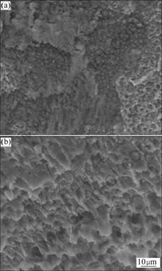
Fig.6 Fracture morphologies of QFP micro-joints soldered with Sn-Ag-Cu solder: (a) IR reflow soldering; (b) Laser soldering
4 Conclusions
1) Solderability of fine pitch QFP devices was investigated with Sn-Ag-Cu and Sn-Cu-Ni lead-free solders. Under the conditions of laser continuous scanning mode as well as the fixed laser soldering time, mechanical properties of QFP micro-joints increase gradually with the increase of laser output power. The optimal mechanical properties of QFP micro-joints are gained when the laser output power increases to an optimal value.
2) As for Sn-Pb solder and Sn-Ag-Cu, Sn-Cu-Ni lead-free solders, mechanical properties of QFP micro-joints soldered with laser soldering system are better than those of QFP micro-joints soldered with IR reflow soldering method. Under the same reflow conditions, mechanical properties of QFP micro-joints soldered with Sn-Ag-Cu lead-free solder are better than those of QFP micro-joints soldered with Sn-Pb solder, while mechanical properties of QFP micro-joints soldered with Sn-Cu-Ni lead-free solder are poor.
3) Fracture morphologies of QFP micro-joints soldered by laser soldering system exhibit the characteristic of toughness fracture, and homogeneous and fine dimples appear under the optimal laser output power, which are much better than those of QFP micro-joints by IR reflow soldering method with the characteristic of toughness fracture and brittle fracture soldered.
References
[1] ZHANG Wen-dian. Practical surface mount technology [M]. Beijing: Electronics Industry Press, 2007: 69-70. (in Chinese)
[2] STAUFFER L, W?RSCH A, G?CHTER B, SIERCKS K, VERETTAS I, ROSSOPOULOS S, CLAVEL R. A surface-mounted device assembly technique for small optics based on laser reflow soldering [J]. Optics and Lasers in Engineering, 2005, 43(3/5): 365-372.
[3] WANG Jian-xin, XUE Song-bai, FANG Dian-song, JU Jin-long, HAN Zong-jie, YAO Li-hua. Effect of diode-laser parameters on shear force of micro-joints soldered with Sn-Ag-Cu lead-free solder on Au/Ni/Cu pad [J]. Trans Nonferrous Met Soc China,2006, 16(6): 1374-1378.
[4] SUN Peng, ANDERSSON C, WEI Xi-cheng, CHENG Zhao-nian, SHANGGUAN Dong-kai, LIU Jo-han. Intermetallic compound formation in Sn-Co-Cu, Sn-Ag-Cu and eutectic Sn-Cu solder joints on electroless Ni(P) immersion Au surface finish after reflow soldering [J]. Materials Science and Engineering B,2006, 135(2): 134-140.
[5] ARULVANAN P, ZHONG Z W. Assembly and reliability of PBGA packages on FR-4 PCBs with SnAgCu solder [J]. Microelectronic Engineering,2006, 83(11/12): 2462-2468.
[6] HAN Zong-jie, XUE Song-bai, LIU Lin, WANG Jian-xin, WU Yu-xiu, HUANG Xiang, WANG Hui. Effects of micro-amount of Ce on microstructures of Sn-Ag-Cu solder and soldered joint [J]. Journal of Rare Earths, 2006, 24(S): 228-232.
[7] MCCLUSKEY F P, DASH M, WANG Z, HUFF D. Reliability of high temperature solder alternatives [J]. Microelectronics and Reliability,2006, 46(9/11): 1910-1914.
[8] WU C M L, YU D Q, LAW C M T, WANG L. Properties of lead-free solder alloys with rare earth element additions [J]. Materials Science and Engineering R, 2004, 44(1): 1-44.
[9] GAO F, TAKEMOTO T. Mechanical properties evolution of Sn-3.5Ag based lead-free solders by nanoindentation [J]. Materials Letters,2006, 60(19): 2315-2318.
[10] SHOHJI I, YOSHIDA T, TAKAHASHI T, HIOKI S. Tensile properties of Sn-Ag based lead-free solders and strain rate sensitivity [J]. Materials Science and Engineering A, 2004, 366(1): 50-55.
[11] XUE Song-bai, YU Sheng-lin. Preparation and characterization on micron power solder of Sn-Ag-Cu-RE[J]. Transactions of the China Welding Institution, 2004, 25(6): 1-3. (in Chinese)
[12] HUANG Hui-zhen, WEI Xiu-qin, ZHOU Lang. Progress in the study on the lead-free solder and its reliability [J]. Electronic Components & Materials, 2003, 22(4): 39-42. (in Chinese)
[13] SUGANUMA K. Lead-free soldering in electronics: Science, technology and environmental impact [M]. New York: Marcel Dekker, 2004.
[14] BOHMAN C F. The laser and microsoldering [R]. AD74-810, Michigan: Society of Manufacturing Engineers, 1974.
[15] BANSE H, BECKERT E, EBERHARDT R, ST?CKL W, VOGEL J. Laser beam soldering―A new assembly technology for microoptical systems [J]. Microsystem Technologies, 2005, 11(2/3): 186-193.
[16] HAN Zong-jie, JU Jing-long, XUE Song-bai, FANG Dian-song, WANG Jian-xin, YAO Li-hua. Microstructures of Sn-Ag-Cu lead-free soldered joints with diode-laser soldering [J]. Journal of Central South University (Science and Technology), 2006, 37(2): 229-234. (in Chinese)
[17] ZHONG Qun-peng, ZHAO Zi-hua, ZHANG Zheng. Development of “fractography” and research of fracture micromechanism [J]. Journal of Mechanical Strength, 2005, 27(3): 358-370. (in Chinese)
[18] ASKELAND D R, PHUL? P P. The science and engineering of materials (reprint edition) [M]. Beijing: Tsinghua University Press, 2005: 153-156.
Foundation item: Project(CX07B_087z) supported by Jiangsu General Colleges and Universities Postgraduate Scientific Research Innovative Plan, China; Project(06-E-020) supported by the Six Kind Skilled Personnel Project of Jiangsu Province, China
Corresponding author: XUE Song-bai; Tel: +86-25-84896070; Fax: +86-25-52112626; E-mail: xuesb@nuaa.edu.cn
(Edited by LI Xiang-qun )

