Analysis and formulation of spur gear stresses with different tip modifications
��Դ�ڿ������ϴ�ѧѧ��(Ӣ�İ�)2019���9��
�������ߣ�A. MAPER S. KARUPPANAN S. S. PATIL
����ҳ�룺2368 - 2378
Key words��gear stresses; friction; linear tip relief; parabolic tip relief
Abstract: Spur gears are widely used in the power transmission mechanism of several machines. Due to the transmitted torque, spur gears experience high stresses which could cause gear tooth failure by surface pitting or root fracture. Tip relief and other gear profile modification have been considered for reducing the induced stresses in the gear tooth. In this work, the influence of tip relief on stresses on a pair of identical spur gear was analyzed using commercial FEA software ANSYS, and formulae for estimating contact and bending stresses were derived. Three cases of gear sets were analyzed; a non-modified pair and another two sets with linear and parabolic tip relief profiles. The non-modified gear set frictionless contact stress was validated against the calculated AGMA pitting resistance, Hertzian contact stress and a reported contact stress value in the literature. The four methods agreed well with each other. Similarly, bending stress was also compared with the AGMA bending strength and Lewis bending stress for validation. Then, friction coefficient was varied from 0.0 to 0.3 with increment of 0.1. The gear contact stress increased up to 11% relative to the frictionless case, whereas bending stress decreased by 6%. Linear tip relief modification was carried out for increasing normalised tip relief values of 0.25 to 1.0 with increment of 0.25. The gear frictionless contact and bending stresses decreased by a maximum of 4% and 2%, respectively. Frictional contact stress increased by up to 7.1% and the bending stress is almost identical with the frictionless case. Parabolic tip relief was also carried out with similar normalised tip relief values. Frictionless contact stress decreased by 5% while frictional contact stress increased by up to 11.5% and the bending stress is also almost identical with the frictionless case. Finally, four formulae were introduced for estimating the contact and bending stresses for a tip modified spur gear.
Cite this article as: A. MAPER, S. KARUPPANAN, S. S. PATIL. Analysis and formulation of spur gear stresses with different tip modifications [J]. Journal of Central South University, 2019, 26(9): 2368-2378. DOI: https://doi.org/10. 1007/s11771-019-4180-x.

J. Cent. South Univ. (2019) 26: 2368-2378
DOI: https://doi.org/10.1007/s11771-019-4180-x

A. MAPER1, S. KARUPPANAN1, S. S. PATIL2
1. Department of Mechanical Engineering, Universiti Teknologi PETRONAS, Bandar Seri Iskandar 32610, Perak Darul Ridzuan, Malaysia;
2. Department of Mechanical Engineering, Manipal University Jaipur, Jaipur 303007, Rajasthan, India
 Central South University Press and Springer-Verlag GmbH Germany, part of Springer Nature 2019
Abstract: Spur gears are widely used in the power transmission mechanism of several machines. Due to the transmitted torque, spur gears experience high stresses which could cause gear tooth failure by surface pitting or root fracture. Tip relief and other gear profile modification have been considered for reducing the induced stresses in the gear tooth. In this work, the influence of tip relief on stresses on a pair of identical spur gear was analyzed using commercial FEA software ANSYS, and formulae for estimating contact and bending stresses were derived. Three cases of gear sets were analyzed; a non-modified pair and another two sets with linear and parabolic tip relief profiles. The non-modified gear set frictionless contact stress was validated against the calculated AGMA pitting resistance, Hertzian contact stress and a reported contact stress value in the literature. The four methods agreed well with each other. Similarly, bending stress was also compared with the AGMA bending strength and Lewis bending stress for validation. Then, friction coefficient was varied from 0.0 to 0.3 with increment of 0.1. The gear contact stress increased up to 11% relative to the frictionless case, whereas bending stress decreased by 6%. Linear tip relief modification was carried out for increasing normalised tip relief values of 0.25 to 1.0 with increment of 0.25. The gear frictionless contact and bending stresses decreased by a maximum of 4% and 2%, respectively. Frictional contact stress increased by up to 7.1% and the bending stress is almost identical with the frictionless case. Parabolic tip relief was also carried out with similar normalised tip relief values. Frictionless contact stress decreased by 5% while frictional contact stress increased by up to 11.5% and the bending stress is also almost identical with the frictionless case. Finally, four formulae were introduced for estimating the contact and bending stresses for a tip modified spur gear.
Key words: gear stresses; friction; linear tip relief; parabolic tip relief
Cite this article as: A. MAPER, S. KARUPPANAN, S. S. PATIL. Analysis and formulation of spur gear stresses with different tip modifications [J]. Journal of Central South University, 2019, 26(9): 2368-2378. DOI: https://doi.org/10. 1007/s11771-019-4180-x.
1 Introduction
Spur gear tooth failures by surface pitting and root fracture are primarily caused by excessive contact and bending stresses. In addition to that, the presence of varying contact friction raises the gear contact stress. To prevent the gear tooth from premature failure and prolong its useful service life, gear tooth profile modification can be implemented. Gear tooth tip modification is defined as the removal of a certain amount of material from the gear tooth flank about the involute curve. Gear tip tooth profile modification, also known as gear tip tooth relief, is a technique used to minimise gear transmission error and reduce high dynamic loads. In this paper, finite element method (FEM) was used to analyze spur gear stresses with the inclusion of tip relief. Three cases of spur gear sets were investigated: a non-modified pair and two other sets with linear and parabolic tip relief profiles. Frictional coefficient was varied from 0.0 to 0.3 with increment of 0.1.
Sufficient examples of stress analysis on gears employing FEM were found in literatures. LIN et al [1] conducted extensive computer simulations on a pair of identical low-contact-ratio gears to investigate the gears dynamic response with the application of both linear and parabolic profile modifications. The aim of this work was to reduce the transmission error which is responsible for gear noise and vibration. In their findings, the authors observed that the two types of tip relief profiles, linear and parabolic generated different gear dynamic loads. Over modification was found to have a damaging effect on the gear because it reduces the contact ratio, which in turn raises the dynamic load. The authors concluded that linear profile modification should only be applied to gears operating at and above design load. Meanwhile, the parabolic profile modification is recommended for application on gears operating below design load to avoid gear resonance. LI et al [2] carried out tooth profile modification on a pair of involute gear using finite element method. They examined the influence of tip relief on the reduction of gear transmission error. Transmission error is defined as the gear tooth deviation from the ideal position during mating. Two sets of gears, a standard and a modified pair, were modelled with two input torque values of 20 and 30 N��m, and with a time increment of 0.02 s. The smaller input torque value of 20 N��m did not produce much difference between non-modified and modified gear transmission error curves. However, with a higher input torque value of 30 N��m, the non-modified gear transmission error curve became erratic, which indicates higher noise and vibration. Meanwhile, the modified gear set resulted in a smooth transmission error curve. The authors concluded that tip relief is an important method not only for transmission error control, but also for the reduction of gear static stress distribution.
BULJANOVI et al [3] examined the influence of linear tip relief profile modification on spur gear stresses. They analyzed two sets of gears, a non-modified pair and a modified pair. The standard meshed gear model experienced additional dynamic loading when double-tooth-contact changed to single-tooth-contact. Also, a rapid change in gear tooth root stress was observed for the un-modified gear model. The gear model with a linear tip relief profile exhibited improved dynamic load response. Contact between meshed gears occurred on the tooth flank with a semi-linear increment and decrement in tooth stress. In addition to that, no rapid stress changes occurred, with smoother gear transmission and without additional dynamic load during contact shift. More studies which considered tip relief have been reported [4-11]. These references included tip relieves and their importance in reducing the induced stresses in gear tooth have been demonstrated.
HASSAN [12] conducted contact stress analysis on a pair of meshed spur gear teeth to obtain the maximum contact stress. The author reported variation in maximum contact stress value with the gear contact position. For instance, contact stress reduced gradually at the beginning of contact and later increased again towards the end of contact. He attributed this to sliding in the contact region at the maximum stress points. Finite element analyses of spur gear contact and bending stresses were conducted by TIWARI et al [13], and JABBOUR et al [14]. The authors validated their findings against Hertzian theory of cylindrical contact stress, Lewis bending equation and AGMA formulae. PATIL et al [15] performed contact stress analysis on a pair of identical spur gear with the inclusion of frictional coefficients using ANSYS APDL. The authors noted that the gear contact stress increased with higher frictional coefficient. For instance, with a friction value of 0.3, the gear stress increased by around 11% relative to the frictionless case. This work demonstrates the influence of friction on the gear contact stress. In another work, PATIL et al [16] developed the friction factor and included it in the AGMA contact stress calculations of gears. Consideration of friction in gear��s contact and bending stress evaluation using FEM can also be observed in many recent works [17, 18]. YUSUF et al [19] carried out similar FEA analysis on spur gear based on Trivariate NURBS and Iso-geometric analysis.
The preceding literature summary shows the need to investigate the influence of both the linear and parabolic tip relief profile modifications of spur gears on the gear contact and bending stresses. Equally, the effect of contact friction on the gear stresses needs to be further examined. Hence, the research gaps identified in the reviewed literature motivate this work.
2 Theoretical spur gear stress calculation
Gear tooth stresses are broadly categorised into bending and contact stresses. Bending stress is theoretically estimated using the Lewis bending equation and AGMA bending strength formula. The Lewis bending equation (Eq. (1)) considers a single gear-tooth as a cantilevered beam carrying a tangential full load applied at the tooth tip.
 (1)
(1)
AGMA bending strength formula (Eq. (2)) is a modification of the Lewis bending equation with the addition of safety factors. The AGMA bending strength formula is the basis of gear bending strength rating, and it must be lower than the maximum allowable bending stress.
 (2)
(2)
Theoretical contact stress is estimated from Hertz theory of contact between two cylinders and the AGMA pitting resistance formula. The Hertzian contact stress formula (Eq. (3)) simplifies gears to be cylinders equivalent to the gears�� pitch circles. The elastic coefficient factor is calculated using Eq. (4) [20, 21]:
 (3)
(3)
 (4)
(4)
The AGMA pitting resistance formula (Eq. (5)) estimates gear likely failure by surface pitting. It incorporates numerous safety factors to cater for the various gear operating conditions.
 (5)
(5)
The values of the parameters used in calculating the theoretical spur gear stresses are listed in Table 1. Meanwhile, the gear specifications and material properties used in this work are listed in Tables 2 and 3,respectively.
Table 1 Parameters for theoretical gear stress calculation

Table 2 Spur gear specifications [15]
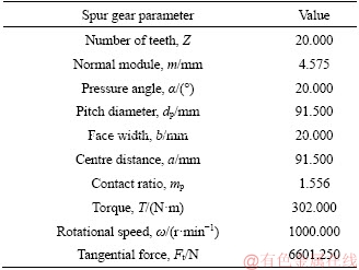
Table 3 Gear mechanical and physical properties [15]

3 Spur gear finite element modelling
Three sets of spur gears were modelled, a gear set with the true involute curve, one pair of gears with linear tip relief and another pair with parabolic tip relief profiles. The gear specifications and material properties are listed in Tables 2 and 3. The gear 3D CAD models were constructed in Autodesk Inventor and then sliced to leave only a pair of three toothed gear segment. The static stress analysis was conducted in ANSYS Workbench. The gear volumes were mapped-meshed by sweeping it with SOLID185, a 3D finite element without mid-side nodes. The contact area was assigned with the contact elements CONTA174 and TARGE170. The gear involute curve was divided into 64 divisions to increase mesh density around the contact area as shown in Figure 1. The meshed model has 144300 elements and 165165 nodes with good mesh size. The mesh convergence test was performed to determine the optimum mesh size.
The load and boundary conditions were applied as shown in Figure 2. The left and right sides of the gear and hub were fixed in all directions. The left and right sides of pinion were fixed tangentially while allowed to move freely in the axial and radial directions. Meanwhile, the pinion hub was fixed in the axial and radial directions and allowed to freely rotate tangentially. Half of the tangential load was applied on the surface of the pinion tooth which is in contact with the gear.

Figure 1 Meshed pinion and gear three-tooth model

Figure 2 Spur gear set with boundary conditions and applied load
Gear tooth profile modification was implemented in Autodesk Inventor . The tip relief was applied on the two contacting teeth of the pinion and the gear along their meshed involute curves. The maximum allowable amount and length of modification were calculated as proposed in Ref. [2]; Ca,max=0.02m and La,max=0.6m, where m is the gear normal module. To calculate the applied amount and length of modification, a range of values were selected for both the normalised amount and length of modification as 0.25, 0.50, 0.75 and 1.0. The applied amount and length of modification were then calculated using Eqs. (6) and (7).
Ca=Cn��Ca,max (6)
La=Ln��La,max (7)
The length and amount of modification define the gear tip relief profile. The length of modification is simply a slanting line connecting two points, one on the gear top land along the outer circle (starting point of modification) and the other on the involute curve (ending point of modification). The amount of modification is defined by two points on the tooth top land along the outer circle, one on the tip point and the other coincident with the starting point of modification. Using these known parameters and the existing geometrical relationships, two lines were drawn from the gear origin (centre) to the starting and ending points of modification. The involute curve rotation angles are the angles formed by these two lines and the gear centreline. Hence, two triangles are formed by these two lines and the line of modification (Figure 3). Also, connecting the starting and ending points of modification with the base circle forms an arc on the base circle equivalent to the length of modification. The various angles and radii involved were then calculated as shown below.

Figure 3 Sketch of triangles formed by line of modification and starting and ending point of radii
First, determine the applied amount and length of modification from Eqs. (6) and (7). Then,
 (8)
(8)
 (9)
(9)
 (10)
(10)
 (11)
(11)
 (12)
(12)
 (13)
(13)
 (14)
(14)
where 1.4725 mm is half the gear top land width.
 (15)
(15)
 (16)
(16)
 (17)
(17)
Determine the value of rT2:
Step 1: Assume a value for distance k (mm), 0
Step 2: Calculate angle i (��),  .
.
Step 3: Calculate side h (mm), h=Lasini.
Step 4: Calculate angle c (��),  .
.
Step 5: Find angle a (��), a=180��-i.
Step 6: Find angle b (��), b=180��-a-c.
Step 7: Calculate rT2 (mm), rT2=  rp
rp
Step 8: Calculate ra, 
 .
.
Using the established tip relief procedure, linear tip modification was applied on the meshed pinion and gear teeth involute edges. The same value was used for both normalised amount and length of modification and it varied from 0.25 to 1.0 with increment of 0.25. Figure 4 shows the application of linear tip relief for a normalised tip relief value of 1.0.
Similarly, parabolic tip relief was also applied using the same normalised amount and length of modification values used for linear tip relief (see Figure 5).
4 Results and discussion
The maximum frictionless contact stress of the non-modified gear set was recorded on the gear tooth subsurface with a value of 1227.5 MPa. Figure 6 shows the contact stress distribution which is higher close to the contact area and decreases away from it.
Similarly, the maximum bending stress was also recorded on the gear tooth root. The stress can be seen to decrease with distance away from the gear tooth fillet area as shown in Figure 7.
The non-modified gear set frictionless contact stress of 1227.5 MPa was compared with the calculated values reported by PATIL et al [15] for validation purposes (see Table 4). The Hertzian contact stress was calculated as 1284 MPa and AGMA pitting resistance was calculated as 1621 MPa, while Ref. [15] reported a maximum contact stress of 1240 MPa. It can be seen that the current result agrees well with the result reported by PATIL et al [15], with a deviation of only 1.0%.
Likewise, the Lewis bending stress and AGMA bending strength were calculated as 234 and 289 MPa, respectively. The current FEA frictionless bending stress of 158.2 MPa was found to be lower than both values by 47.9% and 82.7%, respectively.
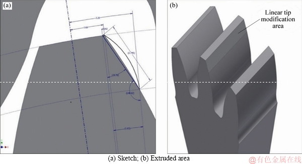
Figure 4 Applied linear tip relief of ��=1.0:

Figure 5 Applied parabolic tip relief of ��=1.0:

Figure 6 Non-modified gear set frictionless contact stress distribution
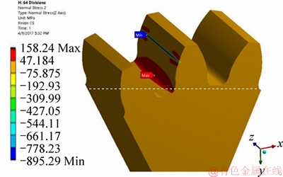
Figure 7 Non-modified gear set frictionless bending stress distribution
Table 4 Deviations of current FEA contact stress compared with theoretical and literature values

The huge deviation is due to the conservative safety factors included in the calculated stresses.
In addition, the gear contact stress increased by 11% when frictional coefficient of 0.3 was imposed. This was expected given that friction elevates stress between two sliding surfaces. PATIL et al [15] also reported an increase of 11% in contact stress for the friction value of 0.3. The gear bending and contact stresses were normalised by dividing them with their respective frictionless stress values to obtain two dimensionless factors:
 and
and  .
.
Figure 8 shows the normalised contact stress factor as a function of coefficients of friction. The normalised contact stress factor increases with the increment in coefficient of friction, with a maximum increment of 11% for friction coefficient of 0.3. However, the normalised gear bending stress factor first decreased as much as 6% for friction values of 0.1 and 0.2 before increasing again by 1% for friction coefficient of 0.3 as shown in Figure 9. This is attributed to stress shifting away from the gear tooth root for a certain range of frictional coefficients. In Figures 8 and 9, Poly. (Sc) is the polynomial curve fit of Sc and Poly. (Sb) is the ploynomial curve fit of Sb.

Figure 8 Normalised contact stress factor variation with increasing frictional coefficients

Figure 9 Normalized bending stress factor variation with increasing frictional coefficients
Figure 10 shows the graphs of normalised contact stress factor as functions of both linear tip relief value and coefficients of friction. Tip profile modification influenced the gear stresses by redistributing the static stresses. Linear tip modified gear frictionless contact stress decreased with increasing tip relief value. The frictionless contact stress decreased by 4% for linear tip relief value of 1.0. The stress reduction with increasing tip relief was anticipated since it influences the gear static stress distribution. Frictional coefficient value of 0.3 increased the gear contact stress by 7.1% and 6.7% for tip relief values of 0.25 and 0.50, and by 6.1% and 6.2% for tip relief values of 0.75 and 1.0,respectively. However, this increase in contact stress with increasing friction values is still lower compared with the non-modified case.
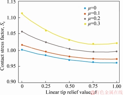
Figure 10 Normalized contact stress factor variation with increasing linear tip relief and frictional coefficient values
Figure 11 shows the normalised frictionless and frictional bending stress factor variation against linear tip relief value. The stress was observed to first decrease by 1% to 2 % with increasing tip relief value before increasing again by 1% for the highest tip relief value of 1.0. This was observed for both frictionless and frictional cases.
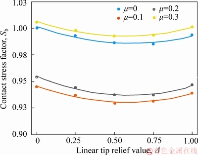
Figure 11 Normalized bending stress factor variation with increasing linear tip relief and frictional coefficient values
Parabolic tip modified gear set stresses also decreased with increasing tip relief value as shown in Figure 12. The frictionless gear contact stress decreased by 5% for parabolic tip relief value of 1.0. Frictional contact stress increased by 11.5% and 10.2% for tip relief values of 0.25 and 0.50, and by 9.3% and 10.4% for tip relief values of 0.75 and 1.0, respectively. It was found that the parabolic tip relief is more suitable for frictional contact stress reduction for frictional values of less than 0.2 while the linear tip relief is more suitable for frictional values of greater than 0.2.

Figure 12 Normalized contact stress factor variation with increasing parabolic tip relief and frictional coefficient values
Figure 13 shows the frictionless and frictional bending stress factor for the parabolic tip modified gear set. It can be seen that the frictionless and frictional bending stress factor are almost identical with the linear tip modified case.

Figure 13 Normalized bending stress factor variation with increasing parabolic tip relief and frictional coefficient values
Four formulae were derived based on the fitted curves�� equations of Figures 10-13 for estimating the contact and bending stresses of a tip modified spur gear for a given tip relief values relative to the non-modified gear stresses. Equations (18) and (19) are the contact stress estimating formulae for linear and parabolic tip modified spur gears, respectively. These equations were developed by finding a relationship to each plot of different friction values in Figures 10 and 12. Subsequently, the relationship between the constants of tip reliefs and friction coefficients were established. The output of the latter relationship is then incorporated in the former relationship. This is similar to obtain the surface plot equation. Origin-pro graph plotting software was used in the process of developing the surface fitted equations.
 (18)
(18)
 (19)
(19)
where Sc is the gear contact stress factor; �� is the normalised gear tip relief value (for both amount and length of tip relief); �� is the coefficient of friction.
Similarly, Eqs. (20) and (21) are the linear and parabolic tip modified spur gear bending stress estimation formulae, respectively.
 (20)
(20)
 (21)
(21)
where Sb is the gear bending stress factor; �� and �� are the same as defined previously.
Equations (18)�C(21) were derived based on the following parameters:
1) Gear normal module, m=4.575 mm.
2) Number of teeth, Z1,2=20 (identical gear set).
3) Friction coefficient, ��=0.0-0.3.
4) The normalised amount and length of modification, ��=0.0-1.0.
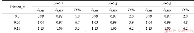
The four formulae were validated against finite element contact and bending stress results. The normalised tip relief values chosen were 0.2, 0.4 and 0.8, and the frictional coefficients considered were 0.0, 0.05 and 0.15. The two methods agreed well with a difference (��) of less than 7% as shown in Tables 5-8.
5 Conclusions
Stress analysis of spur gears is carried out using finite element method and the results are analysed and validated against theory and literature.
1) Non-modified gear set frictionless contact stress is found to be lower than the AGMA pitting resistance, Hertzian contact stress and PATIL et al by 32.1%, 4.6% and 1%, respectively. The bending stress also differed with AGMA bending strength and Lewis bending stress by 82.7% and 47.9%. The gear set frictional contact stress increased by 11% for frictional coefficients of 0.3. Meanwhile the frictional bending stress decreases by 5%-6% for friction value of 0.1-0.2.
Table 5 Comparison of linear tip relief FEA and estimated contact stresses

Table 6 Comparison of parabolic tip relief FEA and estimated contact stresses

Table 7 Comparison of linear tip relief FEA and estimated bending stresses
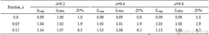
Table 8 Comparison of parabolic tip relief FEA and estimated bending stresses
2) Linear tip modification decreases gear frictionless contact and bending stresses by 4% and 2%, respectively. Meanwhile, frictional contact stress increases by up to 7.1% for frictional coefficient of 0.3, and the frictional bending stress is almost identical with the frictionless case.
3) Parabolic tip modification also decreases gear frictionless contact and bending stresses by 5% and 2%, respectively. Meanwhile, frictional contact stress increases by up to 11.5% for frictional coefficient of 0.3, and the frictional bending stress is almost identical with the frictionless case.
4) Four formulae are derived for estimating the contact and bending stresses of a tip modified spur gear for a given tip relief value relative to the non-modified gear stresses. The results of these formulae are found to agree well with the finite element results for arbitrary conditions with a maximum difference of less than 7%.
Nomenclature
Ca, Ca,max
Cn, Ln
La, La,max
mt
rT2
ST1, ST2
��
��1, ��2
��1, ��2
��1, ��2
��
Applied and maximum allowable amounts of tip relief, mm
Normalized amount and length of tip relief, mm
Applied and maximum allowable lengths of tip relief, mm
Transverse metric module (the same as module, m), mm
Length of the line connecting the origin and the ending point of modification, mm
Lengths of the lines connecting the base circle and a point on the tooth-tip and the point of modification, mm
Angle formed by the lines connecting the base circle and the starting and ending points of modification about the base circle radius, (��)
Angles formed by the lines from the origin to a point on the tooth tip and the ending point of modification with respect to the centreline, (��)
Angles formed by the starting and ending points of modification, the base circle and the gear origin, (��)
Angles formed by the lines connecting the base circle and a point on the tooth tip and the ending point of modification with respect to the centreline, (��)
Nominal tip relief value for both the amount and length of modification, mm
References
[1] LIN H H, OSWALD F B, TOWNSEND D P. Dynamic loading of spur gears with linear or parabolic tooth profile modifications [J]. Mechanism and Machine Theory, 1994, 29: 1115-1129.
[2] LI Z, MAO K. The tooth profile modification in gear manufacture [J]. Applied Mechanics and Materials, 2008, 10: 317-321.
[3] BULJANOVI K, OBSIEGER B. Influence of tip relief profile modification of spur involute gears on stresses [J]. International Journal Advanced Engineering, 2009, 3: 149-158.
[4] DIEZ-IBARBIA A, FERNANDEZ-DEL-RINCON A, DE-JUAN A, IGLESIAS M, GARCIA P, VIADERO��F. Frictional power losses on spurgearswithtipreliefs-The load sharing role [J]. Mechanism and Machine Theory, 2017, 112: 240-254.
[5] DIEZ-IBARBIA��A, FERNANDEZ-DEL-RINCON A, DE-JUAN A, IGLESIAS M, GARCIA P, VIADERO F. Frictional power losses on spurgearswithtipreliefs-The friction coefficient role [J]. Mechanism and Machine Theory, 2018, 121: 15-27.
[6] YE S Y, TSAI S J. A computerized method for loaded tooth contact analysis of high-contact-ratio spur gears with or without flank modification considering tip corner contact and shaft misalignment [J]. Mechanism and Machine Theory, 2016, 97: 190-214.
[7] MA H, ZENG J, FENG R, PANG X, WEN B. An improved analytical method for mesh stiffness calculation of spur gears with tip relief [J]. Mechanism and Machine Theory, 2016, 98: 64-80.
[8] AL-TUBI I S, LONG H, ZHANG J, SHAW B. Experimental and analytical study of gear micro-pitting initiation and propagation under varying loading conditions [J]. Wear, 2015, 328-329: 8-16.
[9] ISBN: 1-55589-839-4. American gear manufacturers association (AGMA) ANSI/AGMA 2101-D04 [S]. 2004.
[10] BEGHINI M, BRAGALLINI G, PRESICCE F, SANTUS C. Influence of the linear tip relief modification in spur gears and experimental evidence [C]// ICEM12-12th International Conference on Experimental Mechanics. Politecnico di Bari, Italy. 2004.
[11] MARKOVI K, FRANULOVI M. Contact stresses in gear teeth due to tip relief profile modification [J]. Engineering Review, 2011, 31: 19-26.
[12] HASSAN A R. Contact stress analysis of spur gear teeth pair, World Academy of Science [J]. Engineering and Technology, 2009, 58: 597-602.
[13] TIWARI S, JOSHI U. Stress analysis of mating involute spur gear teeth [J]. International Journal of Engineering Research & Technology (IJERT), 2012, 1: 1-12.
[14] JABBOUR T, ASMAR G. Tooth stress calculation of metal spur and helical gears [J]. Mechanism and Machine Theory, 2015, 92: 375-390.
[15] PATIL S S, KARUPPANAN S, ATANASOVSKA I, WAHAB A A. Contact stress evaluation of involute gear pairs [J]. Including the Effects of Friction and Helix Angle, Journal of Tribology, 2015, 85: 205-211.
[16] PATIL S, KARUPPANAN S, ATANASOVSKA I. Contact stress analysis of helical gear pairs, including frictional coefficients [J]. International Journal of Mechanical Sciences, 2014, 137(4): 044501.
[17] DENG Song, HUA Lin, HAN Xing-hui, HUANG Song. Finite element analysis of contact fatigue and bending fatigue of a theoretical assembling straight bevel gear pair [J]. Journal Central South University, 2013, 20(2): 279-292.
[18] GOLBAKHSHI H, NAMJOO M. Thermo-structural analysis on evaluating effects of friction and transient heat transfer on performance of gears in high-precision assemblies [J]. Journal Central South University, 2017, 24: 71-80.
[19] YUSUF O T, ZHAO G, WANG W, ONUH S O. Simulation based on trivariate nurbs and isogeometric analysis of a spur gear [J]. Strength Mater, 2015, 47: 19-28.
[20] NISBETT R. G B J K. Shigley��s mechanical engineering design [M]. 9th Ed. New York: mcGraw-Hill, 2011: 673-733.
[21] YEVICK D Y H. Elementary mathematics, fundamental of math and physics for scientists and engineers [M]. New Jersey: Wiley, 2015: 29-30.
(Edited by FANG Jing-hua)
���ĵ���
��ͬ�ݼ�������ֱ����Ӧ�����������
ժҪ��ֱ���ֹ㷺Ӧ���ڶ��ֻ����Ķ��������ṹ�С����ڴ��ڴ��ݵ�Ť�أ�ֱ�����ܵ���Ӧ�����ã�����ܷ��������ʴ��������ѣ������ֳ�ʧЧ��ͨ���ݼ����������������Σ����Լ�С�ֳ��еĸ�ӦӦ��������������������Ԫ��������ANSYS��һ����ֱͬ�����ϵ�Ӧ���ļ�˼���Ӱ������˷������Ƶ��˽Ӵ�������Ӧ�����㹫ʽ��������3�������飺�ǵ��ʳ��������������������Ժ������ߵijݼ����ij����顣���ݼ����AGMA��ʴ���������ȽӴ�Ӧ���������еĽӴ�Ӧ������֤�˷ǵ��ʳ�������Ħ���Ӵ�Ӧ����ͨ�������ַ������õ��Ľ���һ�¡�ͬ���ģ�������Ӧ����AGMA����ǿ�Ⱥ�Lewis����Ӧ�����бȽϣ��Խ�����֤��Ħ��ϵ��������0.1��0.0���ӵ�0.3���������Ħ����������ֽӴ�Ӧ��������11%��������Ӧ��������6%��������0.25����һ���ݼ�����0.25���ӵ�1.0���������Գݼ������Ħ���Ӵ�Ӧ��������Ӧ���ֱ��½���4%��2%��Ħ���Ӵ�Ӧ�����ӵ�7.1��������Ӧ����������Ħ�������ͬ��ʹ�����ƵĹ�һ���ݼ������������߳ݼ������Ħ���Ӵ�Ӧ��������5%��Ħ���Ӵ�Ӧ��������11.5%������Ӧ������Ħ�����������ͬ���������4����ʽ������ݼ�����ֱ���ֵĽӴ�Ӧ��������Ӧ����
�ؼ��ʣ�����Ӧ����Ħ�������Լ�˼���������˼���
Received date: 2018-05-18; Accepted date: 2018-11-10
Corresponding author: S. S. PATIL, PhD, Associate Professor; Tel: +91-9001511483; E-mail: santosh045@gmail.com; ORCID: 0000- 0002-4125-2015

