Effect of working parameters on performance characteristics of hydrostatic turntable by using FSI-thermal model
��Դ�ڿ������ϴ�ѧѧ��(Ӣ�İ�)2018���11��
�������ߣ������� ����ƽ
����ҳ�룺2589 - 2600
Key words��hydrostatic turntable; working parameters; performance characteristics; FSI-thermal coupled model
Abstract: Effects of working parameters on performance characteristics of hydrostatic turntable are researched by applying the fluid-structure-thermal coupled model. Fluid-structure interaction (FSI) technique and computational fluid dynamics (CFD) method are both employed by this new model, and thermal effects are also considered. Hydrostatic turntable systems with a series of oil supply pressures, various oil recess depth and several surface roughness parameters are studied. Performance parameters, such as turntable displacement, system flow rate, temperature rise of lubrication, stiffness and damping coefficients, are derived from different working parameters (rotational speed of turntable and exerted external load) of the hydrostatic turntable. Numerical results obtained from this FSI-thermal model are presented and discussed, and theoretical predictions are in good agreement with the experimental data. Therefore, this developed model is a very useful tool for studying hydrostatic turntables. The calculation results show that in order to obtain better performance, a rational selection of the design parameters is essential.
Cite this article as: HU Jun-ping, LIU Cheng-pei. Effect of working parameters on performance characteristics of hydrostatic turntable by using FSI-thermal model [J]. Journal of Central South University, 2018, 25(11): 2589�C2600. DOI: https://doi.org/10.1007/s11771-018-3938-x.

J. Cent. South Univ. (2018) 25: 2589-2600
DOI: https://doi.org/10.1007/s11771-018-3938-x

HU Jun-ping(����ƽ), LIU Cheng-pei(������)
School of Mechanical and Electrical Engineering, Central South University, Changsha 410083, China
 Central South University Press and Springer-Verlag GmbH Germany, part of Springer Nature 2018
Abstract: Effects of working parameters on performance characteristics of hydrostatic turntable are researched by applying the fluid-structure-thermal coupled model. Fluid-structure interaction (FSI) technique and computational fluid dynamics (CFD) method are both employed by this new model, and thermal effects are also considered. Hydrostatic turntable systems with a series of oil supply pressures, various oil recess depth and several surface roughness parameters are studied. Performance parameters, such as turntable displacement, system flow rate, temperature rise of lubrication, stiffness and damping coefficients, are derived from different working parameters (rotational speed of turntable and exerted external load) of the hydrostatic turntable. Numerical results obtained from this FSI-thermal model are presented and discussed, and theoretical predictions are in good agreement with the experimental data. Therefore, this developed model is a very useful tool for studying hydrostatic turntables. The calculation results show that in order to obtain better performance, a rational selection of the design parameters is essential.
Key words: hydrostatic turntable; working parameters; performance characteristics; FSI-thermal coupled model
Cite this article as: HU Jun-ping, LIU Cheng-pei. Effect of working parameters on performance characteristics of hydrostatic turntable by using FSI-thermal model [J]. Journal of Central South University, 2018, 25(11): 2589�C2600. DOI: https://doi.org/10.1007/s11771-018-3938-x.
1 Introduction
Hydrostatic turntables are broadly applied in ultra precision manufacturing equipments due to their advantages, such as very low friction, virtually no wear between turntable surfaces, high stiffness and damping of fluid film, favorable vibration attenuation property and good rotational accuracy [1]. For sever working conditions, temperature rise of the lubricant and deformations of the turntable cannot be ignored [2]. The mechanism of the fluid film in hydrostatic turntables is a complex multi- physics process, which involves the structural deformation of the turntable, the effect of fluid inertia for different recess geometries and the thermal effects on turntable and the lubricant [3]. However, conventional analytical research work on hydrostatic lubrication analysis only applied classical or modified Navier-Stokes equations or its simplified version, that is, Reynolds equation. It is difficult to give a comprehensive description of the multi-physics lubrication processes of hydrostatic turntables under sever working conditions.
GAO et al [4] proposed an analytical model based on Reynolds equation which was discretized using the Newton method and solved by iterative technique. ZUO et al [5] built the mathematical models of two conical hydrostatic bearings with different compensating devices based on Reynolds equation. And then the performance characteristics of proposed bearings were comparatively studied by means of finite element method. So far, owing to the rapid improvement in computing ability of computers, the solution of complex models becomes possible, and many scholars have carried out lubrication analysis using CFD method based on Navier-Stokes equations. BOMPOS et al [6] presented an integrated simulation study on magnetorheological journal bearings via CFD and finite element method. A CFD model based on Navier-Stokes equation was developed to calculate stiffness and damping coefficients of hybrid bearings by XIONG et al [7]. A numerical identification method of nonlinear dynamic coefficients in plain journal bearing was proposed by ALAKHRAMSING et al [8]. The responses of the bearing are obtained from a CFD model under transient conditions. The internal temperature distribution of hydrostatic thrust bearing was researched based on CFD model by XIA et al [9]. In the above studies, structural deformations, fluid performance, and thermal effects of turntable and lubricant were all predicted separately.
However, hydrostatic turntable is a complex mechanical system. The final performance is governed by several different physical phenomena. So, fluid structure interaction technique and thermal effects of hydrostatic lubrication were also investigated by many researchers. A new transient analysis method based on CFD and FSI techniques was applied by LIN et al [10] to study bearing lubrication problem. Both cavitation and thermal effects were studied. Heat transfer, natural convection and the relationship between the fluid properties and the temperature were considered in the thermal analysis by employing CFD model [11]. The effects of fluid-structure interactions on the deformations, static and dynamic stiffness and setting time under the step load were explored by WANG et al [12]. A FSI model for calculating the elasto-hydrodynamic effects of lubricant film was presented by DHAR et al [13]. It is used to simulate the fluid flow in the lubrication gap. WANG et al [14] studied lubrication performance of water- lubricated journal bearings numerically by using CFD and FSI method.
Actually, many researchers have investigated the influence of working parameters and design parameters on performance characteristics of hydrostatic turntables based on Reynolds equations, CFD or FSI methods in recent years. Based on the stochastic Reynolds equation, ZHANG et al [15] studied the effect of surface roughness on the dynamic performance characteristics of hydrostatic thrust bearings. LIU et al [16] studied dynamic response of the rotor-bearing system with a series of different bearing materials under dynamic unbalanced loads by using CFD-FSI method. The influence of various lubricant species, different recess shapes and a range of speeds on the performance characteristics of hydrostatic bearings was also studied in many references [17�C19].
However, there are few reports on the effects of working conditions of hydrostatic turntable on the lubrication problem based on an integrated FSI-thermal model. This article presents a novel computational model to analyze the performance characteristics of hydrostatic turntables. CFD, FSI and thermal effect are all combined in this multi- physics model. And then the model is verified by the published experimental data. The effects of working parameters (rotational speed of turntable and exerted external load) on performance characteristics for different oil supply pressures, different oil recess depth and different surface roughness parameters of hydrostatic turntables are studied. The conclusions are drawn finally.
2 Theory and method
2.1 Working principle of hydrostatic turntable
A schematic diagram of hydrostatic turntable system compensated by capillary restrictor is shown in Figure 1. The hydrostatic turntable is composed of a turntable and a bearing base. The lubricant which can be able to support external load is pressurized by a constant pressure pump and supplies to the recesses through capillary restrictors.
The lubrication of hydrostatic turntable is a very complex process with varying pressure and temperature in lubricant as well as thermal and elastic deformation in solid domains. On one side, high working pressure and higher pressure peaks of the fluid film exert a significant force on the solid bodies. Fluid-structure interaction mechanism should be considered because of the elastic deformation of the solid surfaces. On the other side, the mechanical energy converts into heat due to viscous friction. This heat increases the temperature of mechanical parts and causes a great influence for the system, inducing a change of lubricant properties in fluid domains and an internal stress condition in solid domains.
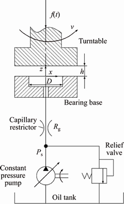
Figure 1 Hydrostatic turntable system
2.2 Governing equation
For continuous Newtonian fluids, the performance of the lubricant film is predicted by using the general conservative Navier-Stokes equations combining the continuity and momentums equations [10]. The following universal formula is used to express these equations:
 (1)
(1)
where �� is density of lubricant; t is time; U is velocity vector. Generalized source term S��, diffusion coefficient ���� and universal variable �� are given by respectively:
 (2)
(2)
where ui is the ith component of velocity; p is the lubricant pressure; �� is dynamic viscosity of the lubricant.
The viscosity of the lubricant is closely related to the temperature distribution of fluid film. Therefore, the next core equation for solving the non-isothermal fluid flow model is energy equation. The energy conservation equation [13] is expressed in differential form:
 (3)
(3)
where E is the energy content per unit mass; �� is thermal conductivity; T is the temperature; �� is stress tensor; Sh is the energy source term. The term represents the heat generated by viscous shear of fluid film; term
  represents heat transfers among fluid domain, solid domain and ambient air; and the term Sh represents the heat caused by mechanical dissipation.
The governing equation of the solid domain [10] is derived from Newton��s second law of motion:
 (4)
(4)
where ��s is the solid density; is local acceleration of the solid region; ��s is Cauchy stress tensor of the solid region; fs is externally applied body force vector.
Thermal modeling of the lubrication interface of hydrostatic turntables mainly involves the thermal models of fluid film and solid domains. The heat transfer of dissipated energy makes fluid domain and solid domain be coupled and influence each other. In addition, it is also essential to describe the thermal deformation of the solid components by a thermo-elastic model. The lubricating gap film thicknesses are affected by the deformation of the solid structure eventually.
As the lubricant is non-isothermal and compressible, the viscosity�Ctemperature, viscosity�C pressure, density�Cpressure and density�Ctemperature effects are considered in fluid domain. The influence of temperature and pressure on viscosity and density of the lubricant is modeled by using fluid properties [13].
 (5)
(5)
 (6)
(6)
where ��0 is dynamic viscosity at initial condition; ��0 is density at initial condition; ��p is pressure�C viscosity coefficient; ��T is temperature�Cviscosity coefficient; ��p is pressure�Cdensity coefficient; ��T is temperature�Cdensity coefficient.
Solid domains influenced by the thermal effect mainly include turntable and bearing base. It follows the generalized Hooke��s law, which considers thermal deformation. The thermal deformation of hydrostatic turntable can be described by thermo-elastic equilibrium differential Eq. (3).
 (7)
(7)
where �� is Lame constant; G is shear modulus; �� is strain; X, Y, Z represent displacements of x, y, z direction respectively; �� is linear thermal expansion coefficient.
The fluid and structure interact with each other, and fluid pressure exerts force on the solid structure to make it move or deform. In turn, the movement or deformation of the solid structure also alters boundary conditions of the fluid. Therefore, the solution variables include not only the usual fluid variables (pressure, velocity, etc.), but also displacement of the boundary. The governing equations are solved using an Arbitrary�C Lagrangian�CEulerian (ALE) formula, which allows the motion of the fluid domain. The elastic deformation of turntable or bearing base can be obtained from Navier��s Eq. (12):
 (8)
(8)
where �� is Poisson ratio; Es is elastic modulus; g is gravitational acceleration.
Assuming that the geometric errors of the turntable and the bearing base are fitted by Fourier series [19], the variation of film thickness due to surface roughness is expressed as:
 (9)
(9)
where ��hf is the variation of film thickness due to surface roughness of the turntable and the bearing base; AE is the amplitude of the wave; ��w is the wavelength; �� is initial phase of the wave.
With the factors such as fluid-structure interaction and thermal effect being taken into account, the final fluid film thickness between turntable and bearing base of hydrostatic thrust bearing should be modified as:

 (10)
(10)
where h is fluid film thickness; h0 is fluid film thickness in initial condition; ��hTw is variation of fluid film thickness due to thermal deformation of the turntable; ��hTb is variation of fluid film thickness caused by thermal deformation of bearing base; ��hpw is variation of film thickness due to fluid pressure deformation of the turntable; ��hpb is variation of film thickness due to fluid pressure deformation of the bearing base; ��hL is variation of fluid film thickness caused by load factor.
The boundary conditions (10) applied to fluid- structure coupling interfaces are kinematic condition (displacement compatibility), dynamic condition (traction equilibrium) and thermal condition (temperature equivalency).
 (11)
(11)
 (12)
(12)
 (13)
(13)
where d represents the displacement; �� is the stress; T is the temperature; subscripts f and s represent fluid and solid respectively; n is normal vector of the fluid structure interface.
Fluid traction is considered the fluid force at fluid-structure interface, acting on the solid structure. For thermal boundary condition, fluid temperature is equal to solid temperature at the fluid-structure interface. In addition, the heat flux also satisfies continuity requirement.
2.3 FSI-thermal model
The fluid-structure-thermal model of the hydrostatic turntable has been developed as a FSI-thermal coupled model. An overview of the FSI-thermal coupled model and information flow between solvers are shown in Figure 2.
A brief summary of the solvers is as follows.
Fluid flow model: a finite volume method for solving Navier-Stokes equation.
Solid structural model: finite element method for turntable and bearing base.
Fluid thermal model: a finite volume solver for energy equations and physical property of the lubricant affected by temperature.
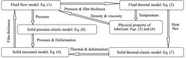
Figure 2 FSI-thermal model of hydrostatic turntable
Solid thermo-elastic model: a finite element solver for heat conduction and thermo-elastic equation for turntable and bearing base.
Solid pressure elastic model: a finite element solver for elastic deformation equations for turntable and bearing base under fluid pressure.
The discretization techniques are finite element method for solid domain and finite volume method for fluid domain. In this research, the solid, fluid and thermal equations are linearized separately and then expressed in a matrix form from systematic prospective, written as:
 ,
,  (14)
(14)
where k is iteration number; Aff, ��Bf and Ff are system matrixes (mass, stiffness, damping, etc), solution variables (pressure, velocity, temperature, etc) and external forces for fluid domain respectively; Ass, ��Bs and Fs are system matrixes (mass, stiffness, damping, etc), solution variables (temperature, stress, etc) and external forces for solid domain respectively; Afs and ASf are fluid structure coupling matrix for the system; Bk and Bk+1 are solutions of step k and k+1 respectively.
According to perturbation theory, the fluid film force (exerted external force) can be linearized by first order Taylor series expansion around an equilibrium position. Then the relationship between the perturbation and the increment of the exerted external force [7, 21] can be expressed as:
 (15)
(15)
where ��f is increment of the exerted external force; K is system static stiffness; C is damping coefficient; ��h is displacement perturbation; is speed perturbation.
System static stiffness and damping coefficient can be obtained by transient calculation based on dynamic mesh technology [7].
 (16)
(16)
Dynamic stiffness Kd of the system can be obtained by the frequency of the exerted external force, system static stiffness and other parameters of the hydrostatic turntable system [22].
 (17)
(17)
where �� is the frequency of the exerted external force; ��n is natural frequency of the hydrostatic turntable system; �� is damping ratio of the system.
2.4 Numerical solution procedure
For the present research methods, almost all numerical studies on hydrostatic lubrication are based on three-dimensional (3D) physical models of the hydrostatic turntable system. The geometric structures of the computational domain are divided into three parts, i.e. the lubricant film in fluid domain, the turntable and the bearing base in solid domain. A geometric model is built using 3D design software SolidWorks. Mesh grids are generated by using the pre-processor ICEM CFD. The key problem examined here is that the size of fluid film thickness is quite small compared to that of other physical features of hydrostatic thrust bearing. To reduce the calculation burden, it is better to use hexahedral cell than tetrahedral cell because the latter one produces a large number of meshes. In order to get a more accurate model, 10 layers are divided across the fluid film. After generation of the mesh grids, they are imported to the CFD code FLUENT, and model properties, boundary conditions, solution methods, etc, are set there.
Two solid domains (turntable and bearing base) and one fluid domain (lubricant) are bound together by two fluid-structure interfaces. And the coupled boundary conditions (that is, temperature equivalence, traction equilibrium and displacement compatibility) are applied to lubricant-bearing base interface and lubricant-turntable interface. In order to transfer information (coupled boundary conditions) across fluid-structure interfaces, the nodes of one mesh in fluid/solid domain should be mapped to the corresponding nodes of the other mesh in solid/fluid domain. Two mappings for fluid-structure interfaces must be performed by using Multi Field Solver solution algorithm. Specifically, for lubricant film analysis, fluid nodes are mapped to solid nodes to transfer information of displacement and heat. Similarly, solid nodes are mapped to fluid nodes to transfer information of heat and pressure.
The flowchart for the FSI-thermal solution is presented in Figure 3. The solution of FSI-thermal model starts with initial settings of calculation conditions (lubricant film thickness, ambient temperature and design parameters of the hydrostatic thrust bearing, etc.). Then a series of models are solved by using ANSYS-FLUENT code. A set of data such as pressure of the lubricant film, temperature of fluid and solid domains and fluid film thickness are obtained. Results are considered acceptable if the differences in lubricant temperature, velocity, pressure and final fluid film thickness are all less than 0.001. Iterations are performed until all of these results converge; otherwise, the same procedure is repeated with updated meshes and boundary conditions in the next iteration.
3 Results and discussion
In order to illustrate the differences between FSI-thermal coupled model and classical model and to analyze the effects of working parameters on the system performance, a number of different models of hydrostatic turntable are built. There are three different oil supply pressures (1.2, 1.5 and 1.8 MPa).

Figure 3 Flowchart for solution of FSI-thermal model
There different depths (1, 2 and 3 mm) of oil recess are set to the bearing base. There are three different grades of roughness parameters (0.2, 0.5 and 0.8 ��m) for bearing surfaces (fluid-structure interface). The corresponding parameters needed in the calculations are partly listed in Table 1.
3.1 Model verification with experimental results
The results of FSI-thermal coupled model will be compared with the solutions of old conventional model and the published experimental data presented in Refs. [9, 20]. The fluid-structure interaction and thermal effects are not considered in old conventional model, as seen in Ref. [20]. The supply pressure of lubricant is 1.2 MPa, the surface roughness parameter is 0.2 ��m and the oil recess depth is 1 mm. The comparisons between the predicted results and the published experimental values in Ref. [20] of turntable displacement at five different exerted external loads (2, 4, 6, 8 and 10 kN) are illustrated in Figure 4. The displacement of turntable increases with the increase of external load. The differences of displacement between predictions of the new FSI-thermal coupled model and experimental results are from 2.37% to 5.15%, which is better than the conventional model results.
Table 1 Parameters of FSI-thermal model
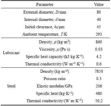
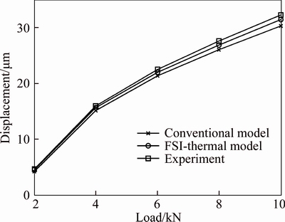
Figure 4 Comparisons of displacement between numerical solutions and experimental results
At five different rotational speeds (1000, 2000, 3000, 4000 and 5000 r/min) of the turntable, the predicted system flow rate and the published experimental data in Ref. [9] are compared in Figure 5. System flow rate increases with the increase of the rotational speed of turntable. Differences of flow rate between the FSI-thermal model predictions and experimental results range from 2.39% to 5.03%.
The predicted temperature rise of lubricant compared with the published experimental results is shown in Figure 6. The temperature rise increases with the increase of rotational speed of the turntable. The differences of temperature rise between the FSI-thermal model and experimental results are from 1.87% to 4.29%, while the conventional model does not have the ability to calculate the temperature rise.
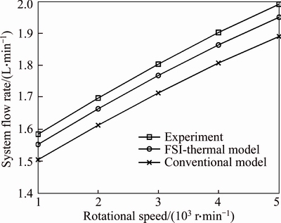
Figure 5 Comparisons of system flow rate between numerical solutions and experimental results
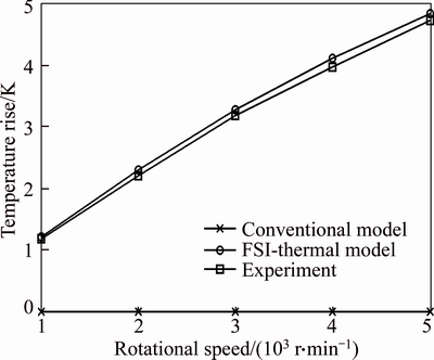
Figure 6 Comparisons of temperature rise between numerical solutions and experimental results
The comparisons of system stiffness between the predicted value and the published experimental results are shown in Figure 7. Compared with the conventional model, the results of the FSI-thermal coupled model are more close to the experimental value. The error of the conventional model increases with the increase of the exerted external load. The higher the load, the more obvious the superiority of the FSI-thermal model.
The comparisons of damping coefficient between the predicted value and the published experimental results are shown in Figure 8. Compared with the conventional model, damping coefficients of the FSI-thermal coupled model are more close to the experimental ones. The error of the conventional model increases with the increase of the rotational speed of the turntable. The superiority of the FSI-thermal model is predominant when it comes to high exerted load.
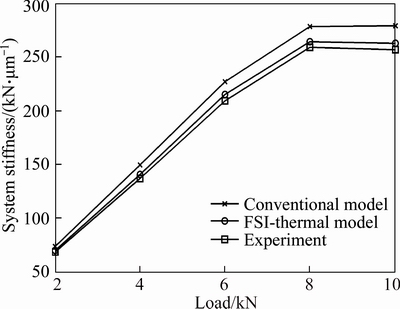
Figure 7 Comparisons of system stiffness between numerical solutions and experimental results
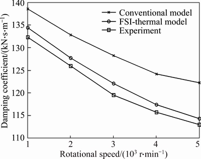
Figure 8 Comparisons of damping coefficient between numerical solutions and experimental results
These numerical predictions agree well with the experimental data. Therefore, this FSI-thermal coupled model can be used as a suitable tool for performance analysis on hydrostatic turntable.
3.2 Effect of rotational speed
Performance parameters (temperature rise, stiffness and damping coefficient) are obtained under these working conditions: the exerted external force is 4 kN and the supply pressure of lubricant is 1.2 MPa.
Figure 9 shows the relationship between temperature rise of lubricant and rotational speed of turntable for different surface roughness parameters (0.2, 0.5 and 0.8 ��m). From Figure 9, it shows that temperature rise of lubricant increases as rotational speed of the turntable increases. The turntable with rougher surfaces will cause more obvious temperature rise. This is owing to the differences of viscous heats caused by the different shear rates, the different velocity gradients across film thickness and the different surface roughness of turntable. The increase in temperature decreases the viscosity of the lubricant, which will influence the performance characteristics of the hydrostatic turntable system.
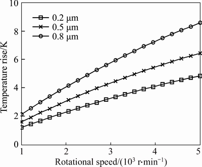
Figure 9 Relationship between temperature rise and rotational speed of turntable
Figure 10 shows relationship between system stiffness coefficient and rotational speed of turntable for different kinds of oil recess depth (1, 2 and 3 mm). From Figure 10, it shows that system stiffness increases as rotational speed of turntable increases. The turntable with deeper oil recess has high system stiffness as a result of the hydrodynamic effect.
Figure 11 shows relationship between system damping coefficient and rotational speed of turntable for different surface roughness parameters (0.2, 0.5 and 0.8 ��m). When the rotational speed of turntable increases from 1000 r/min to 5000 r/min, damping coefficients of the systems are reduced to 120 kN��s/m, 118 kN��s/m and 107 kN��s/m for different surface roughness parameters of turntable respectively. Damping coefficients of hydrostatic turntable with different surface roughness parameters exhibit significant disparities by using the FSI-thermal coupled model.

Figure 10 Relationship between system stiffness and rotational speed of turntable
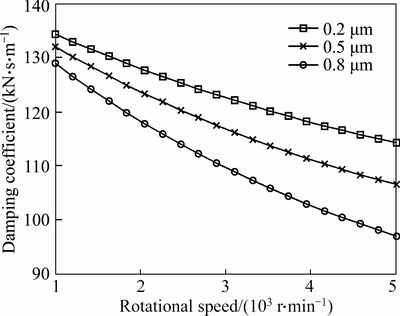
Figure 11 Relationship between damping coefficient and rotational speed of turntable
3.3 Effect of external load
Performance characteristics (system stiffness and damping coefficient) are obtained under these conditions: rotational speed of turntable is 2000 r/min, surface roughness is 0.2 ��m and oil recess depth is 1 mm.
Figure 12 shows relationship between system stiffness and external load for different oil supply pressures (1.2, 1.5 and 1.8 MPa). From Figure 12, it shows that the initial stiffness values are approximate linearly proportional to the oil supply pressure when the load f(t)<6 kN. However, when the hydrostatic turntable system is in the heavy load process, a peak value of system stiffness occurs (oil supply pressure 1.2 MPa). Similar conclusion is also found in Ref. [17]. The same trend will occur in other oil supply pressures (1.5 MPa and 1.8 MPa) when the load is more than 10 kN.
Figure 13 shows relationship between the damping coefficient and the external load for different oil supply pressures (1.2, 1.5 and 1.8 MPa). From Figure 13, it shows that the damping coefficient increases with the increase of external load, and higher oil supply pressure will cause lower damping coefficient.

Figure 12 Relationship between system stiffness and external load
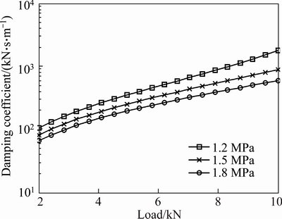
Figure 13 Relationship between damping coefficient and external load
3.4 Effect of working parameters
Under the new FSI-thermal coupled model, performance characteristics of hydrostatic turntable shows obvious differences, especially at high rotational speed or heavy external load. Therefore, future studies are necessary to compare the differences of properties among different working conditions of hydrostatic turntable under an exerted fluctuating force. Performance characteristics (dynamic stiffness and maximum displacement) are obtained under these parameters: oil supply pressure is 1.2 MPa, surface roughness of turntable is 0.2 ��m and depth of oil recess is 1 mm.
Figure 14 shows the effects of different working conditions on dynamic stiffness and maximum displacement of hydrostatic turntable under an exerted fluctuating force. Two working conditions are studied here: working condition A (high rotational speed (4000 r/min) and heavy load (8 kN)) and working condition B (low rotational speed (1000 r/min) and light load (2 kN)). When the frequency of exerted force increases from 0 Hz to 1200 Hz, the minimum dynamic stiffness and maximum displacement of turntable appear around 500 Hz or 800 Hz for working condition A or working condition B respectively. Resonance frequencies, dynamic stiffness and the maximum displacement for the two working conditions are markedly different by use of the FSI-thermal coupled model. To avoid resonance and to evaluate the maximum amplitude near the critical frequency for different working conditions of hydrostatic turntable systems, the new FSI-thermal coupled model becomes necessary.
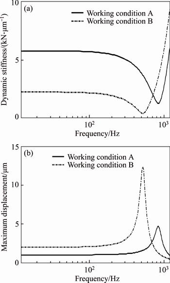
Figure 14 Effects of working parameters on dynamic stiffness (a) and maximum displacement (b)
Above all, compared with the old classical model, more accurate results are produced by the new FSI-thermal coupled model, especially in relation to ��severe�� working conditions (high rotational speed of turntable and heavy exerted external load). In order to acquire better performance of the system under dynamic load, it is a useful tool for adjusting design parameters for different hydrostatic turntable systems.
4 Conclusions
FSI-thermal coupled model is developed to research the effects of working parameters (rotational speed of turntable and exerted external load) on performance characteristics of hydrostatic turntable. The model is based on computational fluid dynamics method and fluid-structure interaction technique, and thermal effects are also taken into account. An experimental validation based on the published references is conducted firstly, and then performance characteristics of different hydrostatic turntable systems with a series of oil supply pressures, various oil recess depth, and different surface roughness parameters are studied. The conclusions are as follows:
1) By employing this FSI-thermal coupled model, performance characteristics (displacement, system flow rate, temperature rise, system stiffness and damping coefficients) of hydrostatic turntable systems can be obtained under different working conditions (rotational speed of turntable and exerted external load). These theoretical results are in good agreement with the published experimental data.
2) The results of new FSI-thermal coupled model are more accurate than those of the old conventional model when it comes to ��severe�� working conditions (high rotational speed of turntable and heavy exerted external load).
3) In order to avoid resonance and to acquire better performance of the system, the FSI-thermal coupled model becomes necessary to adjust design parameters for different hydrostatic turntable systems.
4) The FSI-thermal model can be a very effective tool to analyze effects of working parameters on performance characteristics, which is also very important for the design of the hydrostatic turntables.
References
[1] CHENG Qiang, REN Wei-da, LIU Zhi-feng, CHEN Dong-ju, GU Pei-huo. Load-induced error identification of hydrostatic turntable and its influence on machining accuracy [J]. Journal of Central South University, 2016, 23(10): 2558�C2569. DOI: 10.1007/s11771-016-3317-4.
[2] TANG He-sheng, YIN Yao-bao, ZHANG Yang, LI Jin. Parametric analysis of thermal effect on hydrostatic slipper bearing capacity of axial piston pump [J]. Journal of Central South University, 2016, 23(2): 333�C343. DOI: 10.1007/s11771-016-3078-0.
[3] AGUIRRE G, AL-BENDER F, BRUSSEL H V. A multiphysics model for optimizing the design of active aerostatic thrust bearings [J]. Precision Engineering, 2010, 34(3): 507�C515. DOI:10.1016/j.precisioneng.2010.01.004.
[4] GAO S, CHENG K, CHEN S, DING H, FU H. Computational design and analysis of aerostatic journal bearings with application to ultra-high speed spindles [J]. Proceedings of the Institution of Mechanical Engineers, Part C: Journal of Mechanical Engineering Science, 2017, 231(7): 1205�C1220. DOI: 10.1177/0954406216639344.
[5] ZUO X, WANG J, YIN Z, LI S. Comparative performance analysis of conical hydrostatic bearings compensated by variable slot and fixed slot [J]. Tribology International, 2013, 66(7): 83�C92. DOI: 10.1016/j.triboint.2013.04.013.
[6] BOMPOS D A, NIKOLAKOPOULOS P G. CFD simulation of magnetorheological fluid journal bearings [J]. Simulation Modelling Practice and Theory, 2011, 19(4): 1035�C1060. DOI:10.1016/j.simpat.2011.01.001.
[7] XIONG Wan-li, HOU Zhi-quan, LU Lang, YANG Yue-bing, YUAN Ju-long. Method for calculating stiffness and damping coefficients for hybrid bearings based on dynamic mesh model [J]. Journal of Mechanical Engineering, 2012, 48(23): 118�C126. DOI: 10.3901/JME. 2012.23.118. (in Chinese)
[8] ALAKHRAMSING S, OSTAYEN R V, ELING R. Thermo-hydrodynamic analysis of a plain journal bearing on the basis of a new mass conserving cavitation algorithm [J]. Lubricants, 2015, 3(2): 256�C280. DOI: 10.3390/ lubricants3020256.
[9] XIA Yi-min, ZHANG Gang-qiang, LUO Song-bao, ZHANG Jian-ming. Temperature field distribution of non-spherical hydrostatic bearings for ultra-precision machine tools [J]. Optics and Precision Engineering, 2012, 20(8): 1759�C1764. DOI: 10.3788/OPE.20122008.1759. (in Chinese)
[10] LIN Q, WEI Z, WANG N, CHEN W. Analysis on the lubrication performances of journal bearing system using computational fluid dynamics and fluid-structure interaction considering thermal influences and cavitation [J]. Tribology International, 2013, 64(3): 8�C15. DOI: 10.1016/j.triboint. 2013.03.001.
[11] GAO G, YIN Z, JIANG D, ZHANG X. CFD analysis of load-carrying capacity of hydrodynamic lubrication on a water-lubricated journal bearing [J]. Industrial Lubrication and Tribology, 2015, 67(1): 30�C37. DOI: 10.1108/ilt-03- 2013-0028.
[12] WANG Zhi-wei, ZHA Jun, CHEN Yao-long, ZHAO Wan-hua. Influencing of fluid-structure interactions on static and dynamic characteristics of oil hydrostatic guideways [J]. Journal of Mechanical Engineering, 2014, 50(9): 148�C152. DOI: 10.3901/JME.2014.09.148. (in Chinese)
[13] DHAR S, VACCA A. A fluid structure interaction-EHD model of the lubricating gaps in external gear machines: Formulation and validation [J]. Tribology International, 2013, 62(6): 78�C90. DOI: 10.1016/j.triboint.2013.02.008.
[14] WANG Y, YIN Z, JIANG D, GAO G, ZHANG X. Study of the lubrication performance of water-lubricated journal bearings with CFD and FSI method [J]. Industrial Lubrication and Tribology, 2016, 68(3): 341�C348. DOI: 10.1108/ILT-04-2015-0053.
[15] ZHANG C, JIANG X, WANG L, SUN T, GU L. Effect of surface roughness on the start-stop behavior of air lubricated thrust micro-bearings [J]. Tribology International, 2018, 119: 436�C442. DOI: 10.1016/j.triboint.2017.11.022.
[16] LIU H, XU H, ELLISON P J, JIN Z. Application of computational fluid dynamics and fluid-structure interaction method to the lubrication study of a rotor-bearing system [J]. Tribology Letters, 2010, 38(3): 325�C336. DOI: 10.1007/ s11249-010-9612-6.
[17] BOUZIDANE A, THOMAS M. An electrorheological hydrostatic journal bearing for controlling rotor vibration [J]. Computers and structures, 2008, 86(3�C5): 463�C472. DOI: 10.1016/j.compstruc.2007.02.006.
[18] YADAV S K, SHARMA S C. Performance of hydrostatic tilted thrust pad bearings of various recess shapes operating with non-Newtonian lubricant [J]. Finite Elements in Analysis and Design, 2014, 87: 43�C55. DOI: 10.1016/j.finel.2014.04.009.
[19] WANG Z, ZHAO W, CHEN Y, LU B. Prediction of the effect of speed on motion errors in hydrostatic guideways [J]. International Journal of Machine Tools and Manufacture, 2013, 64(11): 78�C84. DOI: 10.1016/j.ijmachtools.2012. 07.011.
[20] XIA Yi-min, YANG Tian-ren, ZHANG Gang-qiang, LUO Song-bao, YU Hong-yun. Flow field distribution and bearing characteristics of hydrostatic thrust bearing in Nanosys-1000 machine [J]. Optics and Precision Engineering, 2013, 21(1): 144�C150. DOI: 10.3788/OPE.20132101.0144. (in Chinese)
[21] HU Jun-ping, LIU Cheng-pei. Influence of load factor on performance of hydrostatic guideway [J]. Journal of Central South University: Science and Technology, 2017, 48(7): 1741�C1749. DOI: 10.11817/j.issn.1672-7207.2017.07.008. (in Chinese)
[22] CHEN D, FAN J, ZHANG F. Dynamic and static characteristics of a hydrostatic spindle for machine tools [J]. Journal of Manufacturing Systems, 2012, 31(1): 26�C33. DOI: 10.1016/j.jmsy.2010.11.006.
(Edited by YANG Hua)
���ĵ���
Һ�徲ѹת̨��������Ͻ�ģ���乤������������Ӱ��ķ���
ժҪ����������-�ṹ-�����ģ���о��˹���������Һ�徲ѹת̨���ܵ�Ӱ�졣��ģ�Ͳ���������-�ṹ����ã�FSI�������ͼ������嶯��ѧ��CFD������������������ЧӦ�������о��˾��в�ͬ����ѹ�����Ͳ���Ⱥͱ���ֲڶȲ����ľ�ѹת̨ϵͳ����ת̨�Ĺ���������ת̨ת�ٺ�ʩ�ӵ����غɣ��������Ƶ�����ת̨��λ�ơ�ϵͳ���������͵��������նȺ�����ϵ�������ܲ������Ӹ����������ģ�͵õ�����ֵ��������о�������Ԥ����ʵ�������кܺõ��Ǻϡ���ˣ������������ģ����һ���о���ѹת̨�dz����õĹ��ߡ�������������Ϊ�˻�ø��õ����ܣ�����ѡ��Һ�徲ѹת̨ϵͳ����Ʋ����DZ�Ҫ�ġ�
�ؼ��ʣ�Һ�徲ѹת̨���������������ܣ����������ģ��
Foundation item: Projects(51175518, 51705147) supported by the National Natural Science Foundation of China
Received date: 2017-08-08; Accepted date: 2018-03-26
Corresponding author: LIU Cheng-pei, PhD; Tel: +86-13787414786; E-mail: liuchengpei2012@163.com; ORCID: 0000-0003-1887- 5983

