Trans. Nonferrous Met. Soc. China 23(2013) 2265-2269
A new method for separating complex touching equiaxed and lamellar alpha phases in microstructure of titanium alloy
Zhe JI, He YANG, Hong-wei LI, Xiao-guang FAN
State Key Laboratory of Solidification Processing, School of Materials Science and Engineering, Northwestern Polytechnical University, Xi��an 710072, China
Received 21 June 2012; accepted 15 October 2012
Abstract: A new method for separating complex touching equiaxed and lamellar alpha phases in the optical micrograph of titanium alloy was proposed for quantitative characterization. This new method involves three steps. First, concave points of the microstructural feature are identified with a threshold of the concaveness of the corner points which are extracted from the binarized image. Secondly, concave points pairs are selected from the concave points group established by means of marker circle or distance. Third, whether a candidate separation line which connects two concave points within a pair can be accepted or not is determined by the proposed four rules. The obtained results show that this method is effective on separating complex touching microstructural features.
Key words: titanium alloy; microstructural feature; separation method
1 Introduction
Titanium alloys have been widely used in the aerospace field due to their high specific strength, good corrosion resistance and excellent high temperature performance [1,2]. These excellent comprehensive properties depend on optimal combination of equiaxed and lamellar alpha phases. In general, equiaxed phase shows superior ductility and thermal stability, while lamellar phase shows excellent high temperature creep properties, high impact toughness and fracture toughness [3]. Moreover, the combination of these phases significantly affects the mechanical properties of titanium alloys [4]. Hence, quantitative characterization of equiaxed and lamellar alpha phases is significantly important for the optimized mechanical properties of titanium alloys.
However, previous characterization method on the touching equiaxed or lamellar alpha needs to manually identify and separate the different morphologies [5,6]. Apparently, this method is time-consuming and laborious. Therefore, a numerical efficient approach is urgently needed to separate the touching microstructural features automatically. In the field of image processing, the threshold of gray value was usually used as an effective parameter for separating the primary and secondary alpha textures in a duplex microstructure [7-9]. However, different gray values between equiaxed and thick lamellar alpha may not be remarkable.
Therefore, in the present work, a new method based on digital image analysis was proposed to separate touching equiaxed alpha and thick lamellar alpha in a tri-modal microstructure [10] of titanium alloys.
2 Concave point extraction
An apparent feature of touching microstructure is that there is at least one significant concavity along its boundary. The location of concavity can be indicated by its concave point. Thus, whether the microstructural features touching or not can be determined by checking the concave point. The concave point extraction algorithm includes two steps, corner point extraction and concave point identification.
Corner points of a microstructural feature in a binary image can be detected by Harris algorithm which is a well established technique with accurate corner detection performance [11]. Given an image f, the auto-correlation matrix M at position P in the image is

 (1)
(1)
where �� I is the integration scale; �� D is the differentiation scale; g(�� I) is a Gaussian function with deviation �� I;  is the convolution operator; fx and fy are the first image derivatives in the horizontal and vertical direction, respectively.
The commonly used Harris corner response function is given by
 (2)
(2)
where det(M) and trace(M) denote the determinant and the trace of the second matrix M which is defined in Eq. (1); �� is a constant coefficient lying in the interval [0.04,0.15]. High value of the Harris corner response function indicates the location of a corner point.
The Harris algorithm is applied to detecting corner points of a binarized object, as shown in Fig. 1(a). The points indicated by P1-P17 are the corner points detected by Harris algorithm.
The concavity of each corner point is defined by its concaveness, C, which is expressed as [12]
 (3)
(3)
where L is the perimeter of the circle (see Fig. 1(a) at point P1) centered at the corner point and Li is the arc length of the circle inside the object (see Fig. 1(a) at point P1).
Figure 1(b) shows the concaveness of P1-P17. Only the corner points with large concaveness are used to form separation line. Here, a threshold of concaveness 0.5 is used. Thus, the corner points with concaveness lager than 0.5 are extracted, which are considered concave points. The orientation of a concave point is the orientation joining the concave point and the middle point of the arc outside the object (see Fig. 1(a), point B near point P1 is the middle point of the arc outside the object), which is used for separating the microstructural feature with only one concave point.
3 Concave point pairing
The extracted concave points are paired in order to form separation lines. There are many concave points pairing rules, such as nearest neighbor [13] and opposite orientation [12,14]. A new method is proposed to classify the concave points into pairs based on the concave points groups that are classified by the marker circles or distance. The algorithm for concave point pairing includes two steps, classifying concave points into groups and classifying each group into pairs.
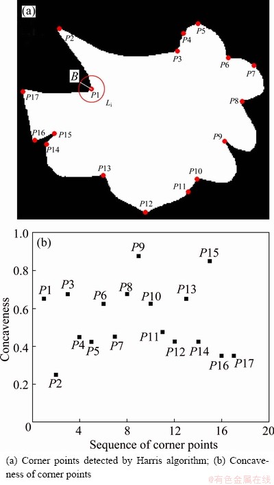
Fig. 1 Schematic representation of concave point extraction
An assemble of two concave points as the candidate for forming separation line is considered a pair. However, it is time-consuming to check every candidate separation line formed by connecting any two concave points. In order to accomplish computational efficiency, the marker circle used to indicate the group of concave points is proposed.
In order to form the marker circle, the center needs to be determined at first, so the skeleton of an object is used. The skeleton of an object is the locus of the centers of the maximal disk that can be inscribed within the object [15]. The thin line in Fig. 2(b) extracted from the gray image (Fig. 2(a)) is the skeleton of the binarized microstructural feature. It can be observed that the skeleton has nearly equal distance to the boundary of the microstructural feature along the normal direction of the skeleton, and the possible separation line must cross the skeleton. The pixels in the skeleton can be divided into three kinds, end points, curve points and junction points which have a single pixel, two pixels and more than two pixels in the skeleton among its 3��3 neighborhood, respectively [15]. The blue points in Fig. 2(b) are the junction points of the skeleton. Apparently, the junction points have nearly equal distance to the boundary of the microstructural feature. Moreover, the concave points (red points in Fig. 2(b)) approach the boundary of the microstructural feature. So, a group of concave points can be easily selected by using the marker circle, which uses junction point as the center and the distance between junction point and its nearest boundary point of microstructural feature as the radius. Distance function is used to determine the radius of the marker circle.

Fig. 2 Concave points pairing
The distance function D of a binary image f, is a transformation that associates to each point X of the definition domain Df of f with its distance to the nearest zero-valued point [15]:
 (4)
(4)
where  is the eight-connected discrete distance between two pixels x and y in a binary image. Figure 2(c) illustrates the distance function of the binary image in Fig. 2(b). Due to their small difference, the distance value at the junction point instead of the distance between junction point and its nearest boundary point is used as the radius and the marker circle is drawn as plotted in Fig. 2(d). For clarity, only the marker circles with radii less than 1.093 ��m or greater than 3.498 ��m are presented. It can be observed that most of the concave points groups can be indicated by the marker circles.
However, due to the complex shape of the microstructural feature, some effective concave points such as the two concave points indicated by G1 in Fig. 2(e) cannot be detected by the marker circle. Hence, if the distance between two concave points which are not detected by marker circle is less than 2.2 ��m, the two points are also considered within a group.
After concave point classification, if a group has two concave points, the two points constitute a pair. If a group has more than two concave points, such as the concave points indicated by the marker circles MK1 in Fig. 2(d) and MK2 in Fig. 2(e), each concave point and its nearest neighbor along the anticlockwise direction of the marker circle constitute a pair. These pairs of concave points are used to form candidate separation lines.
4 Separation line determination
Every pair of concave points can form a candidate separation line. However, the imperfect image binarization, which cannot be avoided in many cases [16], may result in extra concave point such as P in Fig. 2(e) and thus extra candidate separation lines. So, some restrictions have to be supplemented for checking out whether a candidate separation line is correct or not.
1) Length of the separation line. According to the characteristic of the present microstructural features, the separation line is rejected if its length is greater than 2.2 ��m.
2) Crossing the skeleton. The separation line is rejected if it crosses the skeleton more than once or never crosses the skeleton.
3) Area of the separation part. If the area of one of the two separation parts is less than 0.597 ��m2, the separation line is abandoned.
4) Single concave point. If the microstructural feature has only a single concave point, the separation line is constructed along the opposite direction of the concave point orientation.
An application of the four rules on separation of the touching microstructural feature in Fig. 2(b) is shown in Fig. 3. The different microstructural features are presented in different colors and the thin lines between them are the separation lines. It can be observed that the equiaxed and lamellar alpha phases in Fig. 3 have distinct circumscriptions, which is useful for microstructural features quantitative characterization.
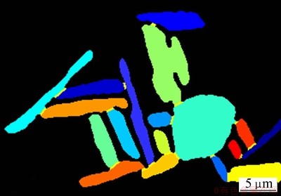
Fig. 3 Separation result of Fig. 2(b)
5 Results
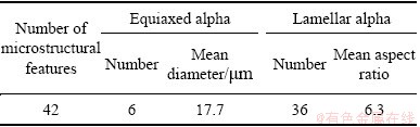
To demonstrate the validity of the proposed method, it was used on a complex touching microstructural feature as shown in Fig. 4(a), which was extracted from the optical micrograph of titanium alloy, at a magnification of 500. The separation result is shown in Fig. 4(b). The total number of the microstructural features and the number of equiaxed and lamellar alpha after separation are listed in Table 1. The separated 6 equiaxed and 36 lamellar alpha phases are presented in different colors and the thin lines are the separation lines. From the processing results, it is clearly seen that the proposed method can separate the microstructural features effectively in despite of the complex touching way of the microstructural features.
After separation, it is easy to quantitatively characterize the microstructural features individually. The diameter of the equiaxed alpha measured by mean intercept length and the aspect ratio of the lamellar alpha measured by the ratio between major axis and minor axis of equivalent ellipse of lamellar alpha are listed in Table 1. Therefore, the present method is more convenient and stable than manual separation for the quantitative characterization of the microstructural features.
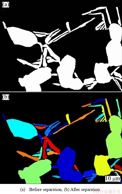
Fig. 4 Separation of complex touching microstructure
Table 1 Quantitative characterization results
6 Conclusions
1) A new method for separating the equiaxed and lamellar alpha in titanium alloy was established, including extraction of concave points, establishment of concave points pairs, and determination of separation lines.
2) Concaveness of a point plays an important role in extracting concave points from corner points of a feature identified by Harris algorithm. The approach by means of a marker circle as well as the distance of two concave points shows good effect on establishing concave points groups to form concave points pairs. Moreover, four rules were proposed for determining correct separation lines.
3) The established method is effective to characterize complex touching microstructural features. Based on the separated results, quantitative analysis in terms of mean size and aspect ratio has been performed.
References
[1] YANG He, FAN Xiao-guang, SUN Zhi-chao, GUO Liang-gang, ZHAN Mei. Recent developments in plastic forming technology of titanium alloys [J]. Science China Technological Sciences, 2011, 54(2): 490-501.
[2] WEISS I, SEMIATIN S L. Thermomechanical processing of alpha titanium alloys��An overview [J]. Materials Science and Engineering A, 1999, 263: 243-256.
[3] ZHOU Y G, ZENG W D, YU H P. An investigation of a new near-beta forging process for titanium alloys and its application in aviation components [J]. Materials Science and Engineering A, 2005, 393: 204-212.
[4] ANKEM S, MARGOLIN H, GREENE C A, NEUBERGER B W, OBERSON P G. Mechanical properties of alloys consisting of two ductile phases [J]. Progress in Materials Science, 2006, 51: 632-709.
[5] COLLINS P C, WELK B, SEARLES T, TILEY J, RUSS J C, FRASER H L. Development of methods for the quantification of microstructural features in ��+��-processed ��/�� titanium alloys [J]. Materials Science and Engineering A, 2009, 508: 174-182.
[6] WANG Kai-xuan, ZENG Wei-dong, SHAO Yi-tao, ZHAO Yong-qing, ZHOU Yi-gang. Quantification of microstructural features in titanium alloys based on stereology [J]. Rare Metal Materials and Engineering, 2009, 38(3): 398-403. (in Chinese)
[7] GERMAIN L, GEY N, HUMBERT M, HAZOTTE A, BOCHER P, JAHAZI M. An automated method to analyze separately the microtextures of primary ��p grains and the secondary ��s inherited colonies in bimodal titanium alloys [J]. Materials Characterization, 2005, 54: 216-222.
[8] THOMAS M J, WYNNE B P, RAINFORTH W M. An alternative method to separate and analyse the microtextures and microstructures of primary alpha grains and transformed beta grains in near-�� titanium alloy Timetal 834 [J]. Materials Characterization, 2005, 55: 388-394.
[9] SALEM A A, GLAVICIC M G, SEMIATIN S L. A coupled EBSD/EDS method to determine the primary- and secondary-alpha textures in titanium alloys with duplex microstructures [J]. Materials Science and Engineering A, 2008, 494: 350-359.
[10] FAN X G, YANG H, SUN Z C, ZHANG D W. Effect of deformation inhomogeneity on the microstructure and mechanical properties of large-scale rib-web component of titanium alloy under local loading forming [J]. Materials Science and Engineering A, 2010, 527: 5391-5399.
[11] GUEGUEN L, PESARESI M. Multi scale Harris corner detector based on differential morphological decomposition [J]. Pattern Recognition Letters, 2011, 32: 1714-1719.
[12] ZHONG Qu-fa, ZHOU Ping, YAO Qing-xing, MAO Ke-jun. A novel segmentation algorithm for clustered slender-particles [J]. Computers and Electronics in Agriculture, 2009, 69: 118-127.
[13] VISEN N S, SHASHIDHAR N S, PALIWAL J, JAYAS D S. AE-automation and emerging technologies: Identification and segmentation of occluding groups of grain kernels in a grain sample image [J]. Journal of Agricultural Engineering Research, 2001, 79: 159-166.
[14] WANG W X. Binary image segmentation of aggregates based on polygonal approximation and classification of concavities [J]. Pattern Recognition, 1998, 31(10): 1503-1524.
[15] RUBERTO C D. Recognition of shapes by attributed skeletal graphs [J]. Pattern Recognition, 2004, 37: 21-31.
[16] BAI Xiang-zhi, SUN Chang-ming, ZHOU Fu-gen. Splitting touching cells based on concave points and ellipse fitting [J]. Pattern Recognition, 2009, 42: 2434-2446.
һ���ѺϽ��е�����Ƭ����ิ��ճ����֯�ָ���·���
�� ������ �ϣ����ΰ��������
������ҵ��ѧ ����ѧԺ�����̼��������ص�ʵ���ң����� 710072
ժ Ҫ��Ϊ�˶��ѺϽ�����֯���ж������������һ�ַָ������Ƭ����ิ��ճ����֯���·������÷��������������裺���ȣ�ͨ�������ֵ������֯ͼ����ÿ���ǵ�İ���ֵ��ȷ�����㡣��Σ����ñ�ʶԲ�Ͱ����ľ���ֵѡȡ����ԡ��������ĸ����ж����Ӱ�����е������������γɵķָ����Ƿ�����ȷ�ķָ��ߡ�������������ø÷���������Ч�طָ��ճ����֯��
�ؼ��ʣ��ѺϽ��۽ṹ���ָ��
(Edited by Jing-hua FANG)
Foundation item: Projects (50935007, 51175428) supported by the National Natural Science Foundation of China; Project (2010CB731701) supported by the National Basic Research Program of China; Project (B08040) supported by the Program of Introducing Talents of Discipline to Universities, China
Corresponding author: He YANG; Tel/Fax: +86-29-8849-5632; E-mail: yanghe@nwpu.edu.cn
DOI: 10.1016/S1003-6326(13)62727-2

