Diving control of underactuated unmanned undersea vehicle using integral-fast terminal sliding mode control
��Դ�ڿ������ϴ�ѧѧ��(Ӣ�İ�)2016���5��
�������ߣ��ں��� ����ƽ ��ˡƼ
����ҳ�룺1085 - 1094
Key words��integral-fast terminal sliding mode control; depth control; underactuated unmanned undersea vehicle
Abstract: The problem of diving control for an underactuated unmanned undersea vehicle (UUV) considering the presence of parameters perturbations and wave disturbances was addressesed. The vertical motion of an UUV was divided into two noninteracting subsystems for surge velocity control and diving. To stabilize the vertical motion system, the surge velocity and the depth control controllers were proposed using backstepping technology and an integral-fast terminal sliding mode control (IFTSMC). It is proven that the proposed control scheme can guarantee that all the error signals in the whole closed-loop system globally converge to the sliding surface in finite time and asymptotically converge to the origin along the sliding surface. With a unified control parameters for different motion states, a series of numerical simulation results illustrate the effectiveness of the above designed control scheme, which also shows strong robustness against parameters perturbations and wave disturbances.
J. Cent. South Univ. (2016) 23: 1085-1094
DOI: 10.1007/s11771-016-0358-7

YAN Zhe-ping(����ƽ)1, YU Hao-miao(�ں���)1, HOU Shu-ping(��ˡƼ)2
1. College of Automation, Harbin Engineering University, Harbin 150001, China;
2. College of Mechanical and Electrical Engineering, Harbin Engineering University, Harbin 150001, China
 Central South University Press and Springer-Verlag Berlin Heidelberg 2016
Abstract: The problem of diving control for an underactuated unmanned undersea vehicle (UUV) considering the presence of parameters perturbations and wave disturbances was addressesed. The vertical motion of an UUV was divided into two noninteracting subsystems for surge velocity control and diving. To stabilize the vertical motion system, the surge velocity and the depth control controllers were proposed using backstepping technology and an integral-fast terminal sliding mode control (IFTSMC). It is proven that the proposed control scheme can guarantee that all the error signals in the whole closed-loop system globally converge to the sliding surface in finite time and asymptotically converge to the origin along the sliding surface. With a unified control parameters for different motion states, a series of numerical simulation results illustrate the effectiveness of the above designed control scheme, which also shows strong robustness against parameters perturbations and wave disturbances.
Key words: integral-fast terminal sliding mode control; depth control; underactuated unmanned undersea vehicle
1 Introduction
The problems for underactuated unmanned undersea vehicles (UUVs) control have increasingly aroused general interest in the field of ocean engineering, due to their theoretical challenges and important applications, as FOSSEN [1-3], ANTONELLI [4] and DO and PAN [5] studied. Since these vehicles are highly autonomy and security, they generally perform some high-risk missions, such as oceanographic mapping survey, seabed resource exploration, submarine rescue, and military applications [6]. Besides their numerous practical applications, the motion control of underactuated UUVs is confronted with serious challenges, because they are highly nonlinear, including parameters perturbations and second-order nonholonomic in their dynamics. The Brockett theorem indicates that the dynamic of an under-actuated UUV cannot be stabilized by using any time-invariant or continuous state feedback control laws [7].
Compared with the case of infinite waters, as an UUV approaches to the free surface or seafloor, its motion equations do not change. However, since the boundary conditions of the flow field is changed, the hydrodynamic coefficients of UUV are affected, that is near-wall effect. This impact is inversely proportional to the distance between the vehicle and the free surface or seafloor [8-10]. It is known that the impact becomes large when the UUV is close to the free surface. Apparent from the near-wall effect, the flow velocity will increase through a narrow channel. Therefore, theoretical calculations and model tests indicate that these hydrodynamic coefficients will appear less than 20% perturbations [10]. Furthermore, the hydro-dynamic coefficients of underactuated UUV are usually obtained by semi-analytic and empirical methods, or model��s experiments [11-12]. However, these hydro-dynamic coefficients obtained above are typically imprecise [1, 3].
When an underactuated UUV sails near the free surface, the states of its motion are affected by wave disturbances. In order to deal with the wave disturbances acting on the underactuated UUV, the circular motion of water parcel in the wave is usually considered as the additional hydrodynamic pressure [13]. Using the approach based on the one described in Refs. [3, 14-15], for the case of a submerged submarine, a standard dynamic model for the underactuated UUV can be established in the absence of wave disturbance. And then the forces and moments resulting from the surf are superimposed on the previous model to furnish an approximation to the underactuated UUV motion in the presence of wave disturbances [15]. In this work, assumption is made that the sea wave state is known and can be described by a spectral density function.
In recent years, most of the researches on the diving control for underactuated UUVs are based on linearized models at operating points, such as linear sliding mode control [16], gain scheduling control [17-18], and robust control [15, 19-20]. However, the motion system of an underactuated UUV can only be stabilized in the local neighborhood of the stable operating points using the approaches, under a series of controllers which are designed for the approximate model. When the coupled nonlinear characteristics plays an important role in the motion of an underactuated UUV, the controllers based on the above linear models cannot guarantee the stability of the UUV motion system. When it comes to the nonlinear model of an UUV with known dynamics, the diving control laws are designed by the State-dependent Riccati Equation [21], the backstepping technique [22], or sliding mode control [23-25]. Almost all of these control strategies are based on accurate dynamic models, however, we cannot obtain an extremely accurate dynamic model in practice due to the presence of parameter perturbations and the unmodeled dynamics. Using the above-mentioned control strategies, the performance of diving control will not be satisfied in presence of non-accurate models.
The sliding mode control (SMC) strategy first originated from the control problem of variable structure system (VSS) in the late 1950��s [26-29]. In the past half century, the traditional SMC has been diffusely used in the control design of various nonlinear systems, due to its strong robustness with regard to external disturbances and model uncertainties [28]. Furthermore, the other advantages of SMC are reduced-order, decoupling, fast response, good dynamic characteristics and so on. Therefore, the traditional SMC is also heavily applied to the motion control of underactuated UUVs. However, in almost all applications for an underactuated UUV with the SMC, the sliding surfaces are linear hyper-planes, which can only guarantee that the system states converge to zeros asymptotically [24]. It means that the system convergence time with traditional linear SMC is highly dependent on the control gain, namely that the high control gain can accelerate the convergence rate and improve the tracking precision. However, excessively high gain may damage the control performance and even generate very serious chattering phenomenon. To solve the aforementioned problems, ZAK [30] proposed terminal sliding mode control (TSMC) in 1988. It has characteristics of fast dynamic response, finite-time convergence, and high steady tracking accuracy and so on. However, the convergence time may be not optimal. To this end, YU and MAN [31] made improvements on the basis of TSMC, and proposed a fast terminal sliding mode control (FTSMC). To avoid the singularity problem of the TSMC, FENG et al [32] proposed a non-singular terminal sliding mode control (NTSMC). For mismatched uncertainties, YANG et al [33-35] developed a series of novel sliding surfaces via a nonlinear disturbance observer. To further improve the steady tracking accuracy and the convergence rate, a new integral-fast terminal sliding mode control (IFTSMC) is proposed in this work. It can stabilize a whole control system in finite time and provide excellent control features with strong robustness to external disturbances and model uncertainties.
In this work, the vertical model of an underactuated UUV was divided into two noninteracting subsystems, including surge velocity control and depth control [15]. And then, the surge velocity controller and the depth controller were designed using the IFTSMC and the backstepping technology. By the Lyapunov stability theory, the robustness and the globally finite-time stability were addressed.
2 Problem formulation
This section mainly introduces the notations used throughout the work. The vertical kinematic and dynamic models of an underactuated UUV are presented. The wave disturbances model is given by the one-parameter Pierson-Moskowitz spectrum, and then, the first- and the second-order wave force and moment are obtained corresponding to the formula. Finally, the diving control objectives of the underactuated UUV are presented.
2.1 Notation
The following notations are used subsequently which originate from the International Towing Tank Conference (ITTC) and the Society of Naval Architects and Marine Engineers (SNAME) [1-4]. To analyze the motion of an underactuated UUV, it is convenient to define two coordinate frames as indicated, namely the inertial reference frame {I} and the body-fixed reference frame {B}. Let denote the Euler angle rotation matrix with argument
 . Consider the underactuated UUV with frames and variables defined according to the SNAME convention, the following notations are listed:
1) [x, y, z]T denotes the coordinate of the origin Ob of the body-fixed reference frame in the inertial reference frame {I}, that is, [xb, yb, zb,]T=[x, y, z]. Due to the research of vertical motion, [x, z]T shows the vertical position coordinates of the vehicle.
2) [ , ��, ��]T denotes the attitude (Euler angles) of an underactuated UUV (the roll, pitch and yaw angles, respectively). In the diving motion, we only consider the pitch angle ��.
3) [u, v, w]T denotes the linear velocities (the surge, sway and heave velocity, respectively) in the body-fixed reference frame {B}. In this work, we only consider the surge and heave velocity, i.e. [u, w]T.
4) [p, q, r]T denotes the angular velocities with respect to each of the respective axis of the body-fixed reference frame {B}. In that way, the pitch angular velocity q denotes the attitude change rate of the vehicle.
5)  denotes the total speed projected into the diving plane.
6) �� denotes the angle of attack, ��=arctan(w/u), u>0.
7) uR is the desired surge velocity of the vehicle, which is constant. The surge velocity error variable is ue=uR-u.
8) zR is the constant desired depth of the vehicle. ze denotes the depth error, ze=zR-z.
2.2 Vehicle motion model
To only analyze the vertical motion of the underactuated UUV, the kinematic and dynamic model of the underactuated UUV can be simplified to model reduced order [1-3]. Hence, the sway, yaw and roll motions can be negligible, i.e., y = 0,= �� = 0, v = 0, p = r = 0 and the corresponding derivatives are zero. Therefore, the standard kinematic model of au UUV in the vertical plane is
 (1a)
(1a)
 (1b)
(1b)
 (1c)
(1c)
Consider an underactuated UUV, there are only three independent control inputs, namely, one stern thruster, one pair of sternplanes and one pair of rudders. However, we consider only the thruster and sternplanes, since the diving motion of the UUV is only analyzed. The forces and moments resulting from the wave disturbances are superimposed on the standard dynamic model of the underactuated UUV in the vertical plane. In the modeling process of the underactuated UUV, it is assumed that the mass distribution of the vehicle is homogeneous and the hydrodynamics drag terms of order higher than two are neglected. And the UUV is considered to be a neutrally buoyant marine vessels. Thus, the dynamic model of the underactuated UUV can be shown as follows
 (2a)
(2a)
 (2b)
(2b)

 (2c)
(2c)
where 


 m and Iq are the combined rigid-body mass and moment of inertia about y axis in {B}, respectively;
  ,
,  and
and  are added mass terms; W and B are the combined rigid-body weight and buoyancy of the underactuated UUV, respectively; zg and zb are the vertical coordinates of the center of gravity and the center of buoyancy, respectively. Xu, Xu|u|, zw, zw|w|, Mq and
  are hydrodynamic coefficients of the linear and quadratic drag terms. ��u denotes the control force along the surge motion of the vehicle and ��q is the control torque that is applied in order to produce angular motion around the y axis of the {B}. Zwave and Mwave are the instantaneous vertical forces and pitch disturbance of the waves acting on the submerged vehicle, respectively, which is given in the next section.
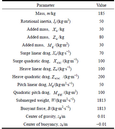
For the above model, the various parameters used for simulation purposes are given, assuming that the various parameters are 20% parameter perturbations. The nominal values of these parameters are listed in Table 1 [36].
Table 1 Rigid body and nominal hydrodynamic parameters of UUV study by PETTERSEN and EGELAND [36]
2.3 Model of wave disturbance
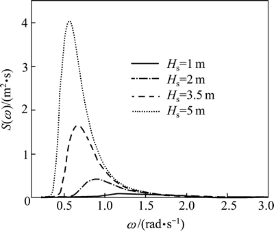
The underactuated UUV, when sailing near the sea surface, is influenced by wave forces and moments. Therefore, so as to design its motion control systems near the sea surface, it is important to research the wave knowledge. The wave disturbances are usually represented as the one-parameter Pierson�CMoskowitz (PM) spectrum written as [3, 37-38]
 (3a)
(3a)
 (3b)
(3b)
 (3c)
(3c)
where S(��) denotes the spectral density in m2/s; �� is the wave frequency; g denotes the acceleration due to gravity in m2/s; and h1/3 is the significant wave height in m.
The peak frequency (modal frequency) ��0 satisfies the following condition [3]:
 (4)
(4)
And then, solving Eqs. (3a) with (3b) and (3c), the peak frequency ��0 is
 (5)
(5)
For a sailing UUV, the aforementioned wave spectrum is altered by encounter angle, formed by the waves and the vehicle directions, and defined as zero when the waves travel in the same direction as the vehicle. Consider the role of the encounter angle, the effective wave frequency is as follows [3, 15, 39]
 (6)
(6)
where �� denotes the encounter angle, which is the heading angle of the vehicle with respect to the wave orientation; and u0 is the total speed of the vehicle.
The wave amplitude for a wave component is [40]
 (7)
(7)
where ���� is the width of the N bands in the frequency windows of interest of the PM spectrum S(��). The wave elevation of a long-crested irregular sea can be expressed as [3]
 (8)
(8)
which is the sum of N harmonic components, where N=2��/���� is the number of wave components (50-100). ��k is the random phase angle of the wave component k. However, the short-crested waves are the most commonly encountered at sea. Then, the wave spectrum changes a 2-D wave spectrum. Furthermore, for a sailing underactuated UUV, the aforementioned wave spectrum is altered by encounter angle. For this case, the wave elevation Eq. (8) becomes [3]

 (9)
(9)
The instantaneous heave forces for the UUV resulting from the wave disturbance can be expressed as two components [15, 40]:
 (10)
(10)
In Eq. (10), Zwavel(t) denotes the first-order wave heave force, the specific expression of which is


And Zwace2(t) is the second-order wave heave force, i.e., the wave drift force is


where Cz1 and Cz2 are the hydrodynamic coefficients;  denotes the volumetric displacement of the vehicle; �� is the seawater density; and F1i is defined in the subsequent section.
The instantaneous pitch moment for the UUV resulting from the wave disturbance can be represented in a similar manner [15, 40]:
 (11)
(11)
In Eq. (11),  denotes the first-order wave pitch moment, and its calculation formula is


And the second-order wave pitch moment is
is
Mwave2(t)=-CM2L��Zwave2(t)
where CM1 and CM2 are the hydrodynamic coefficients; L is the overall length of the UUV. The force F1i is derived from the attenuated static head in the wake of the vehicle depth produced by wave components, and it can be calculated by
 (12)
(12)
where  .
.
2.4 Control objectives
The diving control problems are discussed. The diving motion model of an underactuated UUV is divided into two noninteracting subsystems, including surge velocity control and depth control. The following assumptions are considered:
Assumption 1: Consider an underactuated UUV (1-2):
1) The surge velocity u and heave velocity w can be measured relative to the seabed, and the surge velocity u is constantly positive, i.e., u>0;
2) The desired surge velocity uR>0 and desired depth zR>0 are considered to be the step signals, therefore, 

 and
and 
3) The range of the pitch angle �� is considered as
4) The trigonometric terms cos�� and sin�� are approximated to equal 1 and ��, i.e., cos��=1 and sin��=��;
5) The wave disturbance is considered to be bounded, i.e., there are non-negative constants  and
and such that
 (13)
(13)
Remark 1: For the trigonometric terms of the pitch angle ��, since its range is [-��/9, ��/9], the cosine and sine functions can be done in approximate linearization. The cosine term is approximated to equal 1, namely cos��=1. As the motion control laws are designed to maintain a zero pitch angle, the maximum error produced by the above-mentioned approximate is within ��2.03%. The sine term is used to equal the pitch angle ��, i.e. sin��=��. Using the small angle approximation, the maximum error is within ��1.23%.
Control objective 1: Under the above assumptions, the control inputs ��u and ��q are designed such that the surge velocity u and the depth z of the underactuated UUV globally finite-time track their desired reference values uR and zR as
 (14)
(14)
while all remaining states of the underactuated UUV are maintained to be bounded for every initial condition: 

3 Motion controller design and stability analysis
To develop the diving control strategy, the surge velocity controller and the depth controller are provided by using the backstepping method and the integral-fast terminal sliding mode control (IFTSMC). Since the IFTSMC is based on the integral sliding mode control and the fast terminal sliding mode control, it is provided with common advantages of the above-mentioned SMC.Thus, the IFTSMC can effectively overcome the parameters perturbations and wave disturbances for an underactuated UUV, and can ensure that the entire closed-loop diving motion system globally converges to the origin in finite time.
3.1 Surge velocity controller design
For a given desired surge velocity uR, the surge velocity controller is designed for Eq. (2a) with globally finite-time tracking performance based on the IFTSMC. The error variable ue is defined as follows:
 (15)
(15)
In order to realize the control objective 1, the sliding hyper-plane is defined as
 (16)
(16)
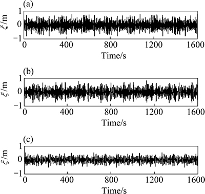
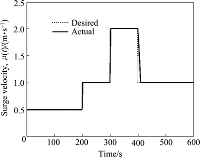
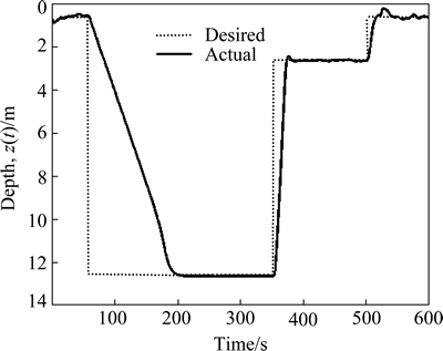
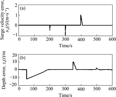
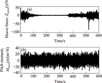
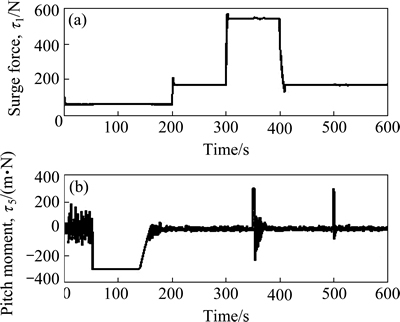
where ��1 and ��2 are positive constant gains to be chosen later; e and f are odd numbers satisfying the following condition: 1 The equivalent control law can be obtained by solving the equation where ��^�� is used to represent the nominal hydrodynamic coefficients of the underactuated UUV. The nominal model parameters can be estimated by semi-analytic and empirical methods or model��s experiments in hydrodynamic tanks. Since the motion of an actual UUV would be affected by the parameters perturbations and wave disturbances, the above-mentioned equivalent control law where the secondary control gain K1 is associated with the upper bound of the parameters perturbations. The following inequalities are introduced, which are used to determine the numerical value of K1. Thus, the specific expression of K1 is as follows: where ��1 is a positive constant to be chosen later. Furthermore, the entire surge control input can be calculated by the following Thus the control lyapunov function (CLF) is chosen as follows Along the solutions of Eq. (17), tacking the derivatives of the above formula and substituting Eq. (22), we can obtain Based on Theorem 2.2 in Ref. [41], if the sliding mode When the sliding mode S1=0 is reached, the surge velocity subsystem dynamics is determined by the following nonlinear differential equation: The origin Calculating the derivative of Eq. (27) along the solutions of Eq. (26), we can obtain Then, the surge velocity tracking error ue can asymptotically converge to a neighborhood of the origin that can be made arbitrarily small along the sliding mode 3.2 Depth controller design In respect to the depth control subsystem, the depth control strategy is proposed by using the backstepping method and IFTSMC for Eqs. (2b) and (2c) with globally finite-time tracking performance. The tracking error variable ze is defined as following: By Assumption 1 and Remark 1, and lack of control input in the heave DOF, the heave velocity w is far smaller than surge velocity u, i.e. u>>w. Thus, the subsystem of the depth kinematics can be simplified as The CLF is chosen as Calculating the derivative of Eq. (31) and using Eq. (30a) and Assumption 1, we can obtain In order to make where ��1 is positive constant to be chosen later. Considering that �� is not true control input, the tracking error variable ��e is introduced as following: Then, In order to let Eq. (35) be negative, the tracking error variable ��e must be stabilized to the origin (��e=0). And then, the sliding hyper-plane is defined as where ��3 and ��4 are positive constant gains to be chosen later; g and h are odd numbers satisfying the following condition: 1 The equivalent control law can be obtained by solving the equation where ��^�� is used to represent the nominal hydrodynamic coefficients of the underactuated UUV. Similarly, in order to overcome the parameters perturbations and wave disturbances, the reaching law is introduced as where the secondary control gain K2 is associated with the upper bound of the parameters perturbations and wave disturbances. The following inequalities are introduced, which are used to determine the numerical value of K2. Thus the specific expression of K2 is as follows where ��2 is positive constant to be chosen later. And then, the total control input for the depth control subsystem is In order to analyze the stability of the pitch angle subsystem under the above-mentioned control strategy, a CLF is familiarly chosen as Calculating the derivative of Eq. (43) along the solutions of Eq. (37), we can obtain If the sliding mode Similarly, when the sliding mode S2=0 is reached, the pitch angle subsystem dynamics is determined by the following nonlinear differential equation: The origin ��e=0 is the terminal attractor of system (58). In order to analyze the stability of system (58), system (58) becomes state-space representation from the differential equation. Let ��1=��e and For analyzing the stability of the pitch angle subsystem on the sliding mode S2=0, a CLF is chosen as Calculating the derivative of Eq. (48) along the solutions of Eq. (47), we can obtain Hence, the pitch angle tracking error ��e can asymptotically converge to a neighborhood of the origin that can be made arbitrarily small along the sliding mode S2=0. And then, the pitch angle tracking error ��e is zero, namely, Thus, the depth tracking error ze can be manipulated to converge to a neighborhood of the origin, which can be realized arbitrarily small and remain there despite of the perturbations. 4 Simulation In this section, to illustrate the effectiveness and robustness of the proposed integral-fast terminal sliding mode control technique (IFTSMC), some numerical simulation results are obtained based on the dynamic model of the underactuated UUV. The diving control is a basic problem of the motion control for the underactuated UUV, which is an indispensable control technology that the UUV achieves wide variety of missions and tasks. When an underactuated UUV sails near the free surface, the motion state of the vehicle is affected by wave disturbances, especially its diving motion. Furthermore, the hydrodynamic coefficients of the underactuated UUV may generate perturbations with the change of the vehicle motion state. Thus, in the procedure for designing the motion controller and simulation, the wave disturbances and hydrodynamic coefficient perturbations must be considered. Therefore, parameters perturbations and wave disturbances are involved in the following simulations. The wave disturbances are described using the one-parameter Pierson-Moskowitz spectrum described in Section 2, see Fig. 1. Considering the sea state that the UUV can operate in practice, the significant wave heights are chosen as 1, 2 and 3.5 m (sea states 3, 4 and 5). The real-time curves of the wave elevation for the states 2, 3 and 4 are shown in Fig. 2. The forces and moments for the UUV resulting from the wave disturbance are discoursed in Section 2, namely, Eqs. (10)-(12). In addition, the hydrodynamic coefficient perturbations are also considered in these simulations, since the boundary condition will inevitablely change when the vehicle performs mission. The hydrodynamic coefficient perturbations are usually less than 20%. Thus, in all simulations, the parameter ranges are set to be [-20%, 20%]. Fig. 1 One-parameter Pierson-Moskowitz spectrum Taking advantage of the diving control strategy in Section 3, we can obtain the diving controller ��u and ��q by selecting the following control gain: ��1=1, ��2=25, ��3=50, ��4=80, ��1=2, ��2=2, e=5, f=3, g=5, h=3 and ��1=10. In the simulation, the underactuated UUV starts from rest, resulting in the initial states of x(0)=0, z(0)=0.6 and ��(0)=0. In the simulation, the desired surge velocity profile of the underactuated UUV is as following: And the desired depth of the underactuated UUV is All simulation results are shown in Figs. 3-7, and the total simulation time is set to 500 s. In Fig. 3, the desired surge velocity uR and actual surge velocity are displayed under the surge velocity controller Eq. (22). Fig. 2 Diagrammatic sketch of wave elevation for sea states 3(a), 4(b) and 5 (c) Fig. 3 Desired surge velocity curve and response curve of actual surge velocity for underactuated UUV Fig. 4 Desired depth and response curve of actual depth for underactuated UUV The desired depth zR and the response curve of actual depth are shown in Fig. 4 under the depth controller Eq. (42). The surge velocity error and depth error are shown in Fig. 5, which demonstrates the surge velocityerror to promptly converge to the origin and the depth error to converge to the origin in finite time since that the dynamic model of the underactuated UUV is provided with strong damping in the heave degree of freedom. In Fig. 6, the instantaneous heave force Zwave(t) and pitch moment Mwave(t) for the UUV resulting from the wave disturbance are displayed. The heave force Zwave(t) would drastically decrease with the increased depth; however, the pitch moment Mwave(t) is inconspicuous. The control inputs are shown in Fig. 7. Fig. 5 Surge velocity error (a) and depth error (b) Fig.6 Instantaneous heave forces (a) and instantaneous pitch moment (b) for UUV resulting from wave disturbance Fig.7 Surge control input force (a) and pitch control input moment (b) 5 Conclusions A new IFTSMC is used to deal with the diving control problem for an UUV in the presence of parameters perturbations and wave disturbances. In order to conquer the above-mentioned control problem, the diving dynamic model for an underactuated UUV is divided into two noninteracting subsystems: surge velocity control and depth control. Then, using the IFTSMC, two controllers are designed for the two subsystems. Based on the Lyapunov stability theory, the stability for these two controllers is proved that they can guarantee all the error signals in the whole closed-loop system globally converge to the origin in finite time. At last, by numerical simulations, the diving control scheme is shown with strong robustness to external disturbances and model uncertainties and can achieve accurate diving control of the underactuated UUV. References [1] FOSSEN T I. Guidance and control of ocean vehicles [M]. 1st ed. New York, USA: John Wiley and Sons Ltd, 1994: 1-56. [2] FOSSEN T I. Marine control systems: guidance, navigation, and control of ships, rigs and underwater vehicles [M]. Tiller, Norway: Marine Cybernetics, 2002: 1-48. [3] FOSSEN T I. Handbook of marine craft hydrodynamics and motion control [M]. 1st ed. New York, USA: John Wiley and Sons Ltd, 2011: 133-186. [4] ANTONELLI G. Underwater robots: Motion and force control of vehicle-manipulator systems [M]. Berlin, Germany: Springer Verlag, 2010: 1-44. [5] DO K D, PAN J. Control of ships and underwater vehicles: Design for underactuated and nonlinear marine systems [M]. London, UK: Springer Verlag, 2012: 295-338. [6] YUH J. Design and control of autonomous underwater robots: A survey [J]. Autonomous Robots, 2000, 8(1):7-24. [7] BROCKETT R W. Asymptotic stability and feedback stabilization: Differential geometric control theory [M]. Boston, USA: Birkhauser, 1983: 181-191. [8] YOUNG S H. Forces and moments acting on a submersible moving beneath the free surface or near a wall [R]. Alexandria, Va: David W. Taylor Naval Ship Research and Development Center, 1987. [9] OLLER E D. Forces and moments due to unsteady motion of an underwater vehicle [D]. Cambridge, Massachusetts: Massachusetts Institute of Technology, 2003. [10] MA Cheng, LIAN Lian. Maneuvering control and simulation technology of underwater vehicle [M]. Beijing, China: National Defense Industry Press, 2009: 29-33. (in Chinese) [11] UENO M, TSUKADA Y, SAWADA H. A prototype of submersible surface ship and its hydrodynamic characteristics [J]. Ocean Engineering, 2011, 38(14/15): 1686-1695. [12] YUE Chun-feng, GUO Shu-xiang, SHI Li-wei. Hydrodynamic analysis of the spherical underwater robot SUR-II [J]. International Journal of Advanced Robotic Systems, 2013, 10: 1-12. [13] NEWMAN J N. Marine hydrodynamics [M]. Cambridge, Massachusetts, USA: Massachusetts Institute of Technology Press, 1977: 1-7. [14] MANDZUKA S. Mathematical model of a submarine dynamics at the periscope depth [J]. Journal of System Simulation, 1998, 46(2): 129-137. [15] MOREIRA L, SOARES C G. H2 and H�� designs for diving and course control of an autonomous underwater vehicle in presence of waves [J]. IEEE Journal of Oceanic Engineering, 2008, 33(2): 69-88. [16] CRISTI R, PAPOULIAS F A, HEALEY A J. Adaptive sliding mode control of autonomous underwater vehicles in the dive plane [J]. IEEE Journal of Oceanic Engineering, 1990, 15(3): 152-160. [17] SILVESTRE C, PASCOAL A. Depth control of the INFANTE AUV using gain-scheduled reduced order output feedback [C]// Proceedings of the 16th IFAC World Congress. Czech Republic: IFAC, 2005: 91-96. [18] SILVESTRE C, PASCOAL A. Depth control of the INFANTE AUV using gain-scheduled reduced order output feedback [J]. Control Engineering Practice, 2007, 15(7): 883-895. [19] FENG Z, ALLEN R. ��Reduced Order H�� control of an autonomous underwater vehicle [J]. Control Engineering Practice, 2004, 12(12): 1511-1520. [20] LAPIERRE L. Robust diving control of an AUV [J]. Ocean Engineering, 2009, 36(1): 92-104. [21] NAIK M S, SINGH S N. State-dependent Riccati equation-based robust dive plane control of AUV with control constraints [J]. Ocean Engineering, 2007, 34(11/12): 1711-1723. [22] LI Ji-hong, LEE P M. Design of an adaptive nonlinear controller for depth control of an autonomous underwater vehicle [J]. Ocean Engineering, 2005, 32(17/18): 2165-2181. [23] JIA He-ming, ZHANG Li-jun, BIAN Xin-qian, YAN Zhe-ping, CHENG Xiang-qin, ZHOU Jia-jia. A nonlinear bottom-following controller for underactuated autonomous underactuated vehicles [J]. Journal of Central South University, 2012, 19(5): 1240-1248. [24] WANG Yao-yao, GU Lin-yi, GAO Ming, JIA Xian-jun, LIU Jun, ZHOU Dong-hui. Depth control of remotely operated vehicles using nonsingular fast terminal sliding mode control method [C]// Proceedings of OCEANS 2013 MTS/IEEE San Diego Conference: An Ocean in Common. San Diego, USA: IEEE, 2013: 1-6. [25] LAKHEKAR G V, SAUNDARMAL. Novel adaptive fuzzy sliding mode controller for depth control of an underwater vehicles [C]// Proceedings of IEEE International Conference on Fuzzy Systems 2013. Hyderabad, India: IEEE, 2013: 1-7. [26] UTKIN V I. Variable structure systems with sliding modes [J]. IEEE Transactions on Automatic Control, 1977, 22(2): 212-222. [27] UTKIN V I. Sliding mode control design principles and applications to electric drives [J]. IEEE Transactions on Industrial Electronics, 1993, 40(1): 23-36. [28] EDWARDS C, SPURGEON S K. Sliding mode control: Theory and applications [M]. New York, USA: Taylor & Francis, 1998: 1-18. [29] ZHANG Niao-na. Terminal sliding mode control theory and applications [M]. Beijing, China: Science Press, 2011: 1-14. (in Chinese) [30] ZAK M. Terminal attractors for addressable memory in neural networks [J]. Physics Letters A, 1988, 133(1/2): 18-22. [31] YU Xing-huo, MAN Zhi-hong. Fast terminal sliding-mode control design for nonlinear dynamical systems [J]. IEEE Transactions on Circuits and Systems I: Fundamental Theory and Applications, 2002, 49(2): 261-264. [32] FENG Yong, YU Xing-huo, MAN Zhi-hong. Non-singular terminal sliding-mode control of rigid manipulators [J]. Automatica, 2002, 38(12): 2159-2167. [33] YANG Jun, LI Shi-hua, YU Xing-huo. Sliding mode control for systems with mismatched uncertainties via a disturbance observer [J]. IEEE Transactions on Industrial Electronics, 2013, 60(1): 160-169. [34] YANG Jun, LI Shi-hua, SU Jin-ya, YU Xing-huo. Continuous nonsingular terminal sliding mode control for systems with mismatched disturbances [J]. Automatica, 2013, 49(7): 2287-2291. [35] YANG Jun, SU Jin-ya, LI Shi-hua, YU Xing-huo. High-order mismatched disturbance compensation for motion control systems via a continuous dynamic sliding-mode approach [J]. IEEE Transactions on Industrial Informatics, 2014, 10(1): 604-614. [36] PETTERSEZN K Y, EGELAND O. Time-varying exponential stabilization of the position and attitude of an underactuated autonomous underwater vehicle [J]. IEEE Transactions on Automatic Control, 1999, 44(1): 112-115. [37] PIERSON W J, MOSKOWITZ L. A proposed spectral form for fully developed wind seas based on the similarity theory of S. A. Kitaigorodsku [R]. Mississippi, USA: Naval Oceanographic Office, US, 1969. [38] ABKOWITZ M A, MURDEY D C, GERRITSMA J, TASAI F, GOODRICH G J, WERMTER R, MATHEWS S T, YAMANOUCHI Y. Report of the seakeeping committee [C]// Proceedings of the 12th International Towing Tank Conference. Rome, Italy: ITTC, 1969: 813-821. [39] LICEAGA-CASTRO E, van der MOLEN G M. Submarine H�� depth control under wave disturbances [J]. IEEE Transactions on Control Systems Technology, 1995, 3(3): 338-346. [40] FALTINSEN O M. Sea loads on ships and offshore structures [M]. Cambridge, UK: Cambridge University Press, 1993: 131-256. [41] HUANG Xiang-qiang, LIN Wei, YANG Bo. Global finite-time stabilization of a class of uncertain nonlinear systems [J]. Automatica, 2005, 41(5): 881-888. (Edited by FANG Jing-hua) Foundation item: Projects (51179038, 51309067) supported by the National Natural Science Foundation of China Received date: 2015-03-23; Accepted date: 2015-07-22 Corresponding author: YU Hao-miao, PhD Candidate; Tel: +86-13946133304; E-mail: yuhaomiao1983@163.com (17)
(17) without the parameters perturbations, which can guarantee the performance of the surge velocity subsystem when its states are on the sliding hyper-plane Eq. (16). Thus, the equivalent control law can be written as
 (18)
(18) cannot ensure a favorable performance of motion system in practice. Therefore, an auxiliary control strategy��a reaching law is introduced. The auxiliary control law
 can be given as
 (19)
(19) (20)
(20)
 (21)
(21) (22)
(22) (23)
(23) (24)
(24) the surge velocity tracking error ue can be manipulated to converge to the sliding mode
  within the finite time
  which satisfies
 (25)
(25) (26)
(26) is the terminal attractor of the system Eq. (26). To analyze the stability of the surge velocity sub-system on the sliding mode , a CLF is chosen as
 (27)
(27) (28)
(28) and remain there despite of the perturbations.
 (29)
(29) (30a)
(30a) (30b)
(30b) (31)
(31) (32)
(32) negative, the pitch angle �� is considered as the virtual control input. The desired values of the pitch angle �� is designed as follows
 (33)
(33) (34)
(34) (35)
(35) (36)
(36)
 (37)
(37) without the parameters perturbations and wave disturbances, which can guarantee the performance of the surge velocity subsystem when its states are located on the sliding hyper-plane (37). Thus, the equivalent control law can be written as
 (38)
(38) (39)
(39) (40)
(40)
 (41)
(41) (42)
(42) (43)
(43) (44)
(44) , the pitch angle tracking error ��e can be manipulated to converge to the sliding mode S2=0 within the finite time t2T, which satisfies
 (45)
(45) (46)
(46) , the state-space equations are as follows:
 (47)
(47) (48)
(48)

 Equation (32) becomes:
 (49)
(49) (50)
(50)