Article ID: 1003-6326(2005)06-1315-07
Simulation of 3D chip shaping of aluminum alloy 7075 in milling processes
DONG Hui-yue(����Ծ)1, KE Ying-lin(��ӳ��)2
(1. College of Mechanical and Energy Engineering, Zhejiang University, Hangzhou 310027, China;
2. State Key Laboratory of Fluid Power Transmission and Control,
Zhejiang University, Hangzhou 310027, China)
Abstract: By adopting an equivalent geometry model of machining process and considering thermo-plastic properties of the work material, a finite element method(FEM) to study oblique milling process of aluminum alloy with a double-edge tool was presented. In the FEM, shear flow stress was determined by material test. Re-meshing technology was used to represent chip separation process. Comparing the predicted cutting forces with the measured forces shows the 3D FEM is reasonable. Using this FEM, chip forming process and temperature distribution were predicted. Chips obtained by the 3D FEM are in spiral shape and are similar to the experimental ones. Distribution and change trend of temperature in the tool and chip indicate that contact length between tool rake face and chip is extending as tool moving forward. These results confirm the capability of FEM simulation in predicting chip flow and selecting optimal tool.
Key words: 7075 alloy; aluminum alloy; milling; FEM; oblique double-edge; chip CLC
number: TG54; TG659 Document code: A
1 INTRODUCTION
Metal cutting is one of the most common manufacturing processes for producing parts of desirable dimensions. Machining operations comprise a substantial portion of the world��s manufacturing infrastructure. Some studies have found that domestic expenditures on machining amount to between 3% and 10% of the annual US gross domestic product(GDP): between ��240 to ��850 billion dollars in 1998[1, 2]. However, despite its obvious economic and technical importance, machining remains one of the least understood of manufacturing operations and the machining parameters are still chosen primarily through empirical tests and the experience of machine operators and programmers. This approach is costly, and while databases have been developed from large numbers of empirical tests, these databases lose relevance as new tool materials, machines and workpiece materials are developed. As a result: A recent survey by a leading tool manufacturer indicates that in the USA the correct cutting tool is selected less than 50% of the time, the tool is used at the rated cutting speed only 58% of the time, and only 38% of the tools are used up to their full tool-life capability. One of the reasons for this poor performance is the lack of the predictive models for machining[3].
Metal cutting is a highly nonlinear and coupled thermo-mechanical process, where the coupling is introduced through localized heating and temperature rising in the workpiece, which is caused by the rapid plastic flow in the workpiece and by the friction along the tool-chip interface[4, 5]. For example, temperature up to 1000�� has been reported in literature. Finite element model(FEM) is an efficient way to model metal machining process and help to understand the operation[6, 7]. Understanding of the material removal process in metal cutting is important in selecting tool material and geometry, and in assuring consistent dimensional accuracy and surface integrity of the finished product, especially in automated production and precision parts manufacturing. Metal cutting modeling has not been easy, and there are lots of problems in the model, such as the method of establishing material model, determination of friction coefficient and heat transfer between rake face of tool and chip interface. It needs more studies to settle these difficulties. Although there are lots of literatures about FEM of metal cutting, majority of them are two-dimensional ones which are not able to represent metal machining operation[8-10]. Three-dimensional FEM of metal cutting is more close to reality than two-dimensional ones. A coupled thermo-mechanical finite element model was constructed under some assumptions in the presented paper. In addition, several special finite element techniques, such as friction model have been implemented to improve the accuracy and efficiency of the finite element simulation. It is believed that these models can be used to optimize the machining parameters, improving tool design and enhancing machining efficiency.
2 DETERMINATION OF EQUIVALENT AND UNDERFORMED CHIP GEOMETRY
2.1 Thickness of equivalent and undeformed chip
In the actual milling operation, the tip of the cutting edge travels on a trochoidal path due to the feed rate and spindle rotation. However, this path can be assumed to be circular for small values of feed per tooth (fz). Thus, only rotational motion of the tool at a given spindle speed was considered in the process model[11] (Fig.1). Although thickness of the machining layer is variable continuously, for fz is very small, it can be approximated using a circular element that has the equivalent constant thickness determined from the area of undeformed chip cross section. Fig.2 shows the equivalent machining layer with constant thickness. The equivalent chip thickness (hequ) can be represented as
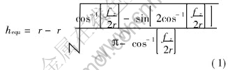
where r is radius of the tool.
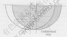
Fig.1 Sketch of undeformed chip between two tool passes with consideration of rotation of tool
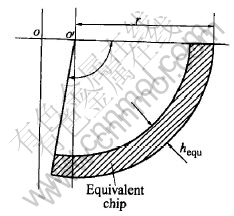
Fig.2 Sketch of equivalent machining layer with constant thickness
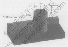
Fig.3 Schematic diagram of milling process
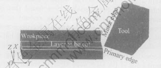
Fig.4 Schematic diagram of oblique double-edge cutting
2.2 Geometry model of milling process
During milling process, the tool moves on a path in X direction and rotates around its axis at the same time as shown in Fig.3. The undeformed chip is equivalent to a machining layer with constant thickness, as stated in Fig.2. The cutting operation can be assumed that tool moves at constant speed and cuts constant-thickness workpiece material layer, as shown in Fig.4. The cutter has a primary cutting edge which is parallel to the cutter axis and a minor cutting edge which is perpendicular to the cutter axis. The length of workpiece shown in Fig.4 is 11mm, and the equivalent chip thickness is 0.15mm. The six degree of freedom of workpiece bottom is constrained. The inclination angle of the tool is 27��.
3 KEY TECHNOLOGIES OF FEM
3.1 Interfacial friction and thermal conductivity
Initial temperatures of tool and workpiece was 20��, and heat transfer coefficient was 11W/(mm2����). During milling process, rake face of tool contact with chip bottom, and there is slip zone and stick zone on the rake face of tool. In this paper, to model the effect of contact friction along the tool-chip interface, the friction law at the tool-workpiece interface is[12]

where m=0.2 and �� is the yield stress at the interface.
3.2 Material model
The workpiece material was aluminum alloy 7075 and tool material was high-speed steel. Both mechanical and thermal properties have been assigned to the workpiece whereas the tool has been defined as rigid for it is harder than workpiece and has been given only thermal properties. Although engineering materials have been studied exhaustively to characterize their stress-strain behavior, most of these studies were carried out at room temperature and only at low levels of strain (approximately 0.3), compared to high temperatures and strain levels witnessed in machining. For modeling convenience and availability of data, the following overstress model was used for 7075[13]
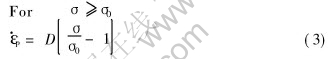
where  is the effective plastic strain rate, �� is the yield stress at a non zero strain rate, ��0 is the static yield stress, D and n are material parameters, respectively (D=1.6275��105, n=1.75[13]).
3.3 Mesh generation
Tetrahedron is used to mesh the workpiece
and the tool. Fig.5(a) shows the shape and surface mesh of tool and workpiece at the beginning of the process. To simulate the chip formation a re-meshing procedure is performed very frequently, so that the workpiece mesh is frequently updated and modified to follow the tool progress, as shown in Figs.5(b)-(c). The total number of element is 32000. This technique makes possible to simulate chip separation from the workpiece without any arbitrary predefinition, and improves the computing efficiency and correctness at the same time.
4 VERIFICATION OF FEM BY EXPERIMENT
To verify FEM of milling process, up milling experiment is done and milling force is measured using dynamometer. Table 1 lists the experiment conditions and Fig.6 shows the experimental setup. The graph in Fig.7 plots the cutting force trends: all the three forces in direction X, Y and Z reach stable values when the simulation reaches a steady state. The same graph allows for a comparison between predicted cutting forces and peak value of measured forces. A very good correlation is found. The maximal error in three directions is 7.9%, 1.4% and 11%, respectively. The factors that cause the existence of error are as follows: 1) there is difference between FEM material model and actual material properties in machining; 2) the
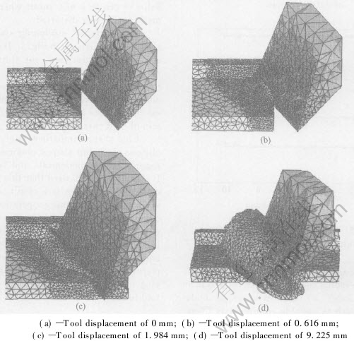
Fig.5 Predicted chip formation of Al alloy at different machining stages
Table 1 Experimental conditions
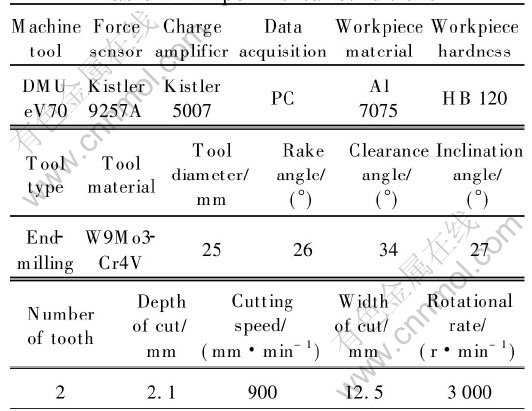
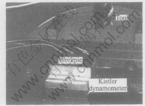
Fig.6 Experimental setup for measurement of cutting forces
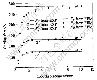
Fig.7 Comparison of cutting forces result from FEM and experiment
tool is assumed as a rigid body and perfect sharp, but it is a hone radius edge in experiment and is an elastic-plastic body; 3) the thickness of undeformed chip which is variable continuously in experiment is equivalent to a constant value in FEM. Considering the above assumptions and simplifications, the result of FEM is acceptable.
5 ANALYSIS OF CHIP SHAPING
5.1 Chip shaping process
Chip is cut off as waste, but an important practical problem concerns the formation of chips produced in machining since this has important implications relative to aspects as follows: 1) safety of the operator; 2) possible damage to workpiece and equipment; 3) handling and disposal of swarf after machining; 4) cutting forces, temperature, and tool life; 5) energy consumption. So chip formation must be studied in detail. In this FEM, chip formation occurs due to natural flow around the tool tip where material splits into two parts one flowing parallel to the tool rake face (chip) and the other flowing under the tool flank face. This approach requires a Lagrangian formulation with frequent automatic re-meshing. This is different from many techniques found in the literature where a chip separation criterion has to be specified in order to let the chip separate from the workpiece (e.g. using superimposed nodes at the parting lines and separation based on effective strain or strain energy density criteria)[14]. In the present work, no chip separation criterion has been specified to DEFORM3D because the chip gets formed as a result of deformation of the workpiece. To be able to obtain the natural formation of the chip due to deformation the automatic re-meshing capability helps to create a new mesh whenever the current mesh gets server distorted.
Four different machining stages of aluminum alloy 7075 are shown in Fig.5. It is obvious that as the tool moves forward, the chip forms and curls naturally, not only in XY plane, but also flows to the side (in Z direction) because the existence of inclination angle. As time goes on, the length (area) of interface between the tool rake face and bottom of chip extends.
Chip shape comparison is given in Fig.8. It is obvious that chip shapes obtained from FEM and experiment are analogical, and both are spirality. It should be emphasized that this type of discontinuous chip formation is a result of geometry alone whereas in the turning operation, discontinuous chips are usually due to fracture of the chip. The regular chip discontinuity associated with milling leads to non-steady-state cyclic conditions of force and temperature. As a tooth engages the workpiece, it receives a strong shock followed by a varying force. The entering shock is detrimental to tool life.
5.2 Distribution of temperature and strain in chip
The cutting temperature is a key factor which directly affects cutting tool wear, workpiece sur-
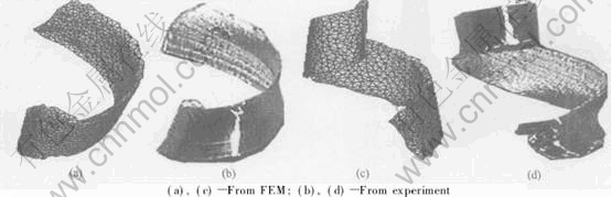
Fig.8 Comparison of chip shape from FEM and experiment
face integrity and machining precision in machining process. Two main heat sources are as: primary heat source along the primary shear zone, and secondary heat source along the tool-chip interface. Primary heat source contributes to the temperature distribution on the tool side indirectly by affecting the heat partition ratio along the tool-chip interface. The curve in Fig.9 represents the temperature evolution. When the tooth engages the workpiece material cutting temperature rises rapidly. When the tool displacement is 1.08mm, that is where the operation achieves steady state, cutting temperature gets a steady value, too. In the machining process, the heat generation is localized. That is why generally the heat loss due to radiation is not considered[14]. Since almost all the plastic work in the workpiece transforms into heat, the fraction of plastic work converted into heat is defined as 0.9[15]. It is estimated that about 80% of heat is generated by the mechanical deformation that creates the chip, about 18% is created at the tool-chip interface or secondary shear zone, and 2% is created at the tool tip. The generated heat is dissipated in three ways: about 75% is taken by the chip, 5% by the workpiece and 20% is conducted through the tool.
Because of the high-speed rotation of tool and the very small thickness of undeformed chip, it is difficult to measure temperature during the milling process. But FEM of milling operation can obtain the temperature distribution at any stage during machining. Fig.10 shows the temperature distribution of the chip and workpiece. Although the maximum strain rate and milling stress generate in the primary shear zone, the temperature of chip-tool interface is maximal, about 308��, and the temperature of the whole chip is very high, too. This is because when the chip begins to form in the
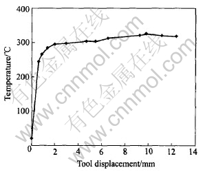
Fig.9 Change of highest temperature in chip during machining process
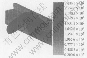
Fig.10 Predicted temperature distribution
primary shear zone, high temperature is result from high strain and high strain rate. The just formed chip with high temperature has no time to cool and contact with tool rake face immediately as the tool moving forward, and friction happens at the same time which contributes the generation of heat. The strain distribution shown in Fig.11 is similar to temperature. When the tool cuts into the material, the chip begins to form and the material starts to strain. The strain achieves its maximum when the chip forms completely, about 0.67. Part of strain is introduced by friction.
6 PREDICTION OF TOOL TEMPERATURE
Tool temperature is related with chip forming
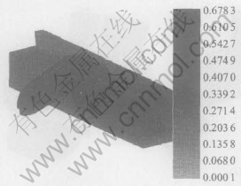
Fig.11 Predicted strain distribution
process closely, and these temperatures increase tool wear development. It is significant to adjust machining parameters or adopt appropriate tool if it is possible to predict the changing contact of tool-chip and tool temperature timely. But it is difficult to measure tool temperature experimentally, and the measured temperature is just local. The range of highest temperature is more significant than local temperature. Using FEM to simulate metal machining process can get tool temperature distribution and the range of highest temperature, so FEM is the right-hand to optimize tool geometry or select optimal tool.
The changing trend of highest temperature in tool is given in Fig.12. Comparing Fig.12 with Fig.9, it is apparent that the highest temperature
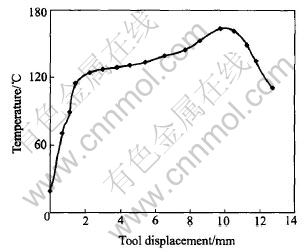
Fig.12 Change of highest temperature in tool during machining process
in chip can be as high as 308��, but tool is just 164��. Tool temperature increases rapidly when the tool just cuts into the material, and increases slowly when the cutting operation comes to steady stage, until the tool cuts out of the material. The reasons of this phenomenon are as follows: 1) as chip temperature rises, the amount of heat that transfers into the tool increases, too; 2) when the cutting operation comes to steady state, the contact length of tool-chip increases continuously, which is in accordance with the changing trend of cutting force. From contour of tool temperature shown in Fig.13, it is known that the region with
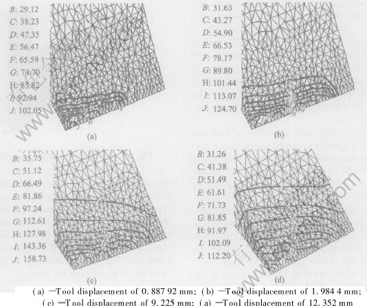
Fig.13 Contour of changing temperature in tool
high temperature in the tool is enlarging during machining process, which proves that the percentage of heat absorbed by the tool and contact length of tool-chip increases. In actual metal cutting, it is the tool rake face and near the tool tip where the highest temperature occurs, but in this paper it is the tool tip not the rake face where the highest temperature exists. This is because that the tool is perfectly sharp, and the rake angle and clearance angle are all very large. When the tip absorbs as mush amount of heat as usual, the increased amplitude of temperature is great. That is to say, the ability of containing heat of the tip is poor.
7 CONCLUSIONS
1) Comparison of predicted chip shape with actual chip shows reasonable agreement. Temperature analysis of chip and tool indicates the contact length of chip and tool rake face, which is very difficult to measure by experiment. It was possible to increase tool life by varying the size of the chip contact length on the rake face of the tool while machining. The methodology can be used to select optimal machining parameters and improve tool design, and lengthy and expensive trial and error experiment process can be avoided.
2) Because of some assumptions, the FEM may not replicate the actual metal cutting process completely. Future work must be done to improve the FEM of metal cutting.
REFERENCES
[1]Wince J N. Modeling Chip Formation in Orthogonal Metal Cutting Using Finite Element Analysis [D]. Mississippi: Mississippi State University, 2002.
[2]Shaw M C. Metal Cutting Principals [M]. Oxford: Oxford Press, 1984. 544.
[3]Astakhov V P, Shvets S V. A system concept in metal cutting [J]. Journal of Material Processing Technology, 1998, 79(1):189-199.
[4]Lei S, Shin Y C, Incropera F P. Thermo-mechanical modeling of orthogonal machining process by finite element analysis [J]. International Journal of Machine & Manufacture, 1999, 39(5): 731-750.
[5]Huang Y, Liang S L. Modeling of cutting forces under turing conditions considering tool wear effect [J]. Journal of Manufacture Science and Engineering, 2005, 127(2): 262-270.
[6]YANG Xiao-ping, Liu C R. A new stress-based model of friction behavior in machining and its significant impact on residual stresses computed by finite element method [J]. International Journal of Material Science, 2002, 44(4): 703-723.
[7]YANG Yong, KE Ying-lin, DONG hui-yue. Constitutive model of aviation aluminum-alloy material in metal machining [J]. Trans Nonferrous Met Soc China, 2005, 15(6): 854-859.
[8]SHI Guo-qin, DENG Xiao-min. Chandrankanth Shet. A finite element study of friction in orthogonal metal cutting [J]. Finite Elements in Analysis and Design, 2002, 38(9): 863-883.
[9]Ozel T, Altan T. Process simulation using finite element method-prediction of cutting forces, tool stresses and temperatures in high-speed flat end milling [J]. International Journal of Machine Tools & Manufacture, 2000, 40(5): 713-738.
[10]Baker M. An investigation of the chip segmentation process using finite elements [J]. Technische Mechanik, 2003, 23(1): 1-9.
[11]Shatla M, Kerk C, Altan T. Process modeling in machining, part 2: validation and applications of the determined flow stress data [J]. International Journal of Machine Tools & Manufacture, 2001, 41(11): 1659-1680.
[12]Ceretti E, Lazzaroni C, Menegardo L, et al. Turning simulations using a three-dimensional FEM code [J]. Journal of Materials Processing Technology, 2000, 98(1): 99-103.
[13]Potdar Y K. Measurements and Simulations of Temperature and Deformation Fields in Transient Orthogonal Metal Cutting [D]. Lowa: The Cornell University, 2001.
[14]Ramesn M V, Seetharamu K N, Ganesan N, et al. Finite element modeling of heat transfer analysis in machining of isotropic materials [J]. International Journal of Heat and Mass Transfer, 1999, 42(9): 1569-1583.
[15]Guo Y B, Liu C R. 3D FEM modeling of hard turning [J]. Journal of Manufacturing Science and Engineering, 2002, 124: 189-199.
(Edited by LONG Huai-zhong)
Foundation item: Project(50435020) supported by the National Natural Science Foundation of China; Project(2005037259) supported by the China Postdoctoral Science Foundation Received date: 2005-03-18; Accepted date: 2005-09-28
Correspondence: DONG Hui-yue, PhD; Tel: +86-571-87951061; E-mail: zjudhy@163.com

