J. Cent. South Univ. Technol. (2011) 18: 244-249
DOI: 10.1007/s11771-011-0686-6

Structure realization method for collapse threshold of plastic deformation in train collision condition
TIAN Hong-qi(田红旗)1, 2, GAO Guang-jun(高广军)1, 2, YAO Song(姚松)1, 2,
XU Ping(许平)1, 2, LIU Hui(刘辉)1, 2
1. Key Laboratory of Traffic Safety on Track of Ministry of Education, Central South University,
Changsha 410075, China;
2. School of Traffic & Transportation Engineering, Central South University, Changsha 410075, China
? Central South University Press and Springer-Verlag Berlin Heidelberg 2011
Abstract: To protect passengers, absorb enough kinetic energy and meet the special requirements for trains which are different from the other means of transportation, a method is presented to realize the plastic deformation threshold based on three main aspects of train connection structure, crashworthy vehicle structure, energy-absorbing component. In practical engineering, trains need enough strength and stiffness to transfer longitudinal force under the normal operation condition, and have to produce controllable large plastic deformation to absorb energy shortly under the collision condition. To realize the structural damage threshold of connecting structure in terminal end, two control methods are also proposed which can be divided as the parametric method based on ‘extrusion’ and ‘cutting’ theories; the method which can cut the connecting components between coupler-buffer devices and train bodies and separate them away when the damage thresholds of coupler-buffer devices are more than the pre-supposed damage thresholds. The damage thresholds can be realized based on changing the parameters of the number of shearing bolts, material parameters, etc. To realize the collision threshold of energy-absorbing components of trains, a control method is presented based on the ways of setting plastic deformation induced structure, local hole and pre-deformation structure. To realize the threshold of the controllable plastic structure of energy-absorbing vehicles, a control method is proposed for the multi-level longitudinal stiffness of train terminal structures.
Key words: damage threshold; train crashworthiness; plastic deformation; energy-absorbing structure
1 Introduction
Collision issue is one of the main accidents for trains. To protect passengers and reduce the loss in accidents, an effective way is to absorb kinetic energy by plastic deformation process based on optimizing the structures of trains. This method is becoming more and more important and is adopted commonly by scientists in the world [1-7].
In traffic and transportation engineering, the largest difference between train and other kinds of transportation is the marshalling manner. The cars of a train are usually connected by various coupler-buffer devices. So, the collision issue of trains has its special characteristics, which can be summarized as follows. 1) In the normal operation and braking situation, the structure of train should have several important characteristics to guarantee the safety of the running train, including enough strength and rigidity capability, meeting the corresponding requirements of some standards, which makes the train have good performance of transferring longitudinal force without plastic deformation and fatigue failure. 2) In collision accidents with high running speed, the structure of train has to meet some requirements to protect the passengers, including collapse in the pre-determined area, producing a large plastic deformation and absorbing enough kinetic energy. So, it is necessary to study the critical condition of train collapse, which can also be regarded as the issue of the damage threshold of plastic deformation under train collision condition.
2 Control method for collapse threshold of train connecting structures
2.1 Control method for collapse threshold of coupler- buffer devices with energy-absorbing components
Train connecting devices are the most fundamental and important connecting parts between cars, which are used in transferring train traction and compressive force, alleviating longitudinal impact in normal operation and shunting situations of trains. When train collision happens, the automatic couplers will be against each other and destroyed firstly, whose collapse mode will produce a significant effect to the subsequent motion and plastic deformation of cars.
For the cars with shorter energy absorption section, to increase the energy absorption, energy-absorbing components are always set in the coupler-buffer devices based on theories of ‘extrusion’ and ‘cutting’. And the basic principle can be given as follows: when the longitudinal force is higher than the damage threshold, the process of ‘extrusion’ and ‘cutting’ will be triggered, then energy-absorbing components of coupler-buffer devices will be crushed.
1) The principle of “extrusion” threshold control process. A taper is set in the initial position of collapse tube. When the coupler-buffer device reaches the largest distance of buffer, the lever of coupler will push the cylinder and the taper against the enlarged-collapse tube, which produces the plastic deformation. The collapse threshold can be adjusted by changing the initial slope. The diagram of the ‘extrusion’ process is shown in Fig.1.
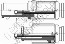
Fig.1 Diagram of ‘extrusion’ process: 1―Taper; 2―Cylinder; 3―Bolt and nut; 4―Enlarged-collapse tube
2) The principle of ‘cutting’ threshold control process. The ‘cutting’ equipment is comprised of cylinder, stem with cutter and removable locating sleeve. The cylinder and stem are positioned in the middle of the coupler. The locating sleeve is used to limit the stem to only move along the axis of the cylinder. When two couplers crash, the cutter (horniness material) will cut the inside surface of cylinder (soft materials) to absorb the collision energy. The diagram of the ‘cutting’ process is shown in Fig.2.
The relationship between the impacting force along the cutting direction and cutting parameters, geometrical parameter of the cutter is important for realizing the ‘cutting’ threshold. Based on the statistical orthogonal
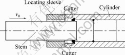
Fig.2 Diagram of ‘cutting’ process
regression method, a common equation about the upper key parameters is presented as
 (1)
(1)
where F is the impacting force along the cutting direction, C is a constant related to the processing material and the cutting condition, b1, b2, b3 and b4 are statistical constants, ap is the cutting depth, d is the width of cutter, γ is the angle of cutter, and v is the initial cutting velocity.
Based on the previous research results, some empirical equations of the impacting force F can be given as follows.
When the material of cutter is cemented carbide YT15 and the material of work piece is 45# steel, the corresponding empirical equation is displayed as
 (2)
(2)
When the material of cutter is cemented carbide YT15 and the material of work piece is aluminium alloy, the corresponding empirical equation is displayed as
 (3)
(3)
From Eqs.(1)-(3), it can also be gotten that, the impacting force along the cutting direction has a strong correlation with the cutting depth, the width of the cutter, the angle of the cutter and the initial cutting velocity. The damage threshold can be realized based on controlling the width of the cutter, the angle of the cutter and the cutting depth.
2.2 Control method for collapse threshold of coupler- buffer connecting devices without energy- absorbing components
Due to the fact that the impact force of the coupler-buffer device is transferred to underframe through the plate seat and the installation seat of coupler-buffer device, the damage threshold of the coupler-buffer connecting devices can be realized by controlling the connecting strength between the plate seat/installation seat and the underframe. When the longitudinal force is higher than this threshold, the connection between the coupler and the underframe will be invalid and the coupler-buffer device will be separated from the car and will not be involved in the subsequent collision. This damage threshold is the induced load for the collision of adjacent cars.
And the impact threshold can be realized by adjusting the strength, quantity and distribution of the sheared bolts and clinch bolts.
3 Control method for impact threshold of energy-absorbing components under train collision condition
3.1 Mode of setting local hole in energy-absorbing structure
Car body is composed of thin-walled element structures, whose performance can determine the crashworthiness of a whole car. In recent years, the crashworthiness of thin-walled structures has been studied [8-14].
Because of the abrupt change of cross-section caused by holes, the stress around the holes increases sharply on account of local stress concentration, which induces plastic deformation and leads to local buckling around the holes [15-18]. Under longitudinal impact loads, the structure continues to yield large plastic deformation and absorb kinetic energy.
Principle of this control mode can be demonstrated by the following analysis based on a specific langloch as displayed in Fig.3: the factor of stress concentration is related with the ratio of the length to the diameter, a/r, and the ratio of the diameter to the width of plate, r/B. The relationship is given in Fig.4.

Fig.3 A schematic diagram of langloch
It can be seen from Fig.4 that, 1) when a/r is limited in the range of 1-4, the factor of stress concentration will decrease when a/r increases; 2) when a/r is more than 4, the factor of stress concentration is almost constant; 3) the factor of stress concentration will decrease with the increase of r/B. While the nominal stress will increase with the increase of hole area which is controlled by r/B. And a deformation series of box-beam structure with local holes is shown in Fig.5. So, the impact threshold can be realized by controlling the position of hole, the diameter of hole and the thickness of plate.

Fig.4 Variation of factor of stress concentration of langloch with ratio of length to diameter (a/r) and ratio of diameter to width (r/B)

Fig.5 Deformation series of box-beam structure with local holes: (a) First moment; (b) Second moment; (c) Third moment
3.2 Mode of setting plastic deformation induced structure in energy-absorbing structure
To control the initial peak of impact force of energy-absorbing structure and make the energy- absorbing component yield large plastic deformation when the peak impact force is higher than the pre-supposed collision threshold, a suitable plastic deformation induced structure can be settled in the energy-absorbing structure to guide it in the pre-supposed deformation mode effectively [19-20]. Principle of this control mode is the same as the mode of setting local hole described in Section 3.1.
The common plastic deformation induced structure includes several kinds, such as triangle pit, rectangular groove, and arc groove.
And the impact threshold can be realized by controlling the geometry, depth and position of plastic deformation induced structure. The energy-absorbing component with circular arc groove and the round thin-wall pipe with transition circular arc chamfer are shown in Fig.6 and Fig.7, respectively.

Fig.6 Energy-absorbing component with circular arc groove
3.3 Mode of setting pre-deformation structure in energy-absorbing structure
This control mode is realized based on the following steps: Firstly, transfer the two sides of square tubes to corrugated plate; Secondly, set the wave peak and wave trough of corrugated plate as the pre-deformation structure; Then, the induced structure will buckle successively in pre-deformation structure when collision happens; Finally, the process of the whole large deformation of parts can be controlled automatically. And the impact threshold can be realized by controlling the wavelength, amplitude and thickness of plate [21]. The energy-absorbing component with pre-deformation structure is shown in Fig.8.
4 Control method for threshold of controllable plastic deformation structure in crashworthy car
To fulfill the threshold of the controllable plastic structure of energy-absorbing cars, the end structure of car body can be designed as the multi-stage longitudinal stiffness structure [22].

Fig.7 Round thin-wall pipe with transition circular arc chamfer

Fig.8 Energy-absorbing component with pre-deformation structure
During the elastic deformation stage, the relationship among the longitudinal impacting force Fe, the longitudinal stiffness k and the longitudinal deflection δe can be demonstrated as
Fe∝kδe (4)
Each stiffness k corresponds to an elastic deformation variable δe when the elastic impacting force Fe is a constant.
When the impacting force Fe is higher than the controllable plastic deformation threshold, the structure will yield the plastic deformation. For the structure with plastic deformation, the relationship among the plastic impacting force Fp, longitudinal stiffness k and longitudinal plastic deformation δp will show nonlinearity and the plastic impacting force Fp will decrease quickly. Then, the plastic impacting force Fp will fluctuate in a limited range with the increase of the longitudinal plastic deflection δp.
Based on the analysis above, it is seen that the maximal elastic impacting force Fe is equal to the controllable plastic deformation threshold. So, the controllable plastic deformation threshold can be realized by controlling the multi-stage longitudinal stiffness of the end structure.
Besides, the multi-stage longitudinal stiffness of the end structure can also be used in solving the issue of non-stationary buckling deformation during long distance plastic deformation. The longitudinal stiffness is strengthened gradually from end to middle. Each stage has a corresponding initial peak impacting force.
The means of realizing the multi-stage longitudinal stiffness are summarized as follows.
1) Control the shape of energy-absorbing beam (such as straight square, straight tapered, cylindrical, cone), the quantity and array combination of energy- absorbing beams and the thickness of plate; and set the plastic deformation induced structure.
2) Installing the isolated honeycomb. Due to the fact that the impacting force of isolated energy-absorbing component is almost stationary during the colliding process, which can further reduce the initial peak impacting force. The isolated honeycomb is always installed in front of cars. The plastic deformation threshold of the front part of car can be realized by choosing the material and sectional area.
3) To control the large plastic deformation of draft sill by sequent fold-collapse mode, by opening holes in the upper coving plate of draft sill, the longitudinal stiffness of draft sill will be weakened properly. Utilizing the stress concentration effect, the stress around the circular hole will increase obviously, so the local initial buckling will arise firstly around the holes. Principle of this control mode is the same as the mode of setting local hole described in Section 3.1.
5 Conclusions
1) For the coupler-buffer with energy-absorbing component, the collapse threshold can be realized by controlling the ‘extrusion’ or ‘cutting’ parameters.
2) For the coupler-buffer without energy-absorbing component, the collapse threshold can be realized by the following measures: changing the strength, quantity and distribution of the sheared bolts or clinch bolts. When the longitudinal force is higher than this threshold, the sheared bolts or clinch bolts will be broken and the coupler-buffer will be separated from the underframe of the car body.
3) The collision threshold of energy-absorbing component can be realized based on the ways of setting plastic deformation induced structure, local hole and pre-deformation structure.
4) The threshold of the controllable plastic structure of energy-absorbing vehicle can be realized based on controlling the multi-level longitudinal stiffness of the end structure of train.
References
[1] YAMAKAWA H, OKU T, FUNATSU K, UJITA Y. A study on energy absorbing members for improvement of train crashworthiness [C]// 10th AIAA/ISSMO Multidisciplinary Analysis and Optimization Conference. Albany, New York, 2004: 650-655.
[2] GAO G J, TIAN H Q. Train’s crashworthiness design and collision analysis [J]. International Journal of Crashworthiness, 2007, 12(1): 21-28.
[3] DIAS J P, PEREIRA M S. Analysis and design for train crashworthiness using multibody models [J]. Vehicle System Dynamics, 2004, 40(S): 107-120.
[4] KOYAMA T, YAMAKAWA H, FUNATSU K, UJITA Y. Structural optimization for improvement of train crashworthiness [C]// 10th AIAA/ISSMO Multidisciplinary Analysis and Optimization Conference. Albany, New York, 2004: 641-649.
[5] TYRELL D, PERLMAN A B. Evaluation of rail passenger equipment crashworthiness strategies [J]. Transportation Research Record, 2003, (1825): 8-14.
[6] CUARTERO J, LIZARANZU M. Evaluation of passenger railroad car roll over crashworthiness [J]. International Journal of Crashworthiness, 2006, 11(5): 419-424.
[7] HOSSEINI-TEHRANI P, NANKALI A. Study on characteristics of a crashworthy high-speed train nose [J]. International Journal of Crashworthiness, 2010, 15(2): 161-173.
[8] KAYA N, OZT?RK F. Multi-objective crashworthiness design optimisation of thin-walled tubes [J]. International Journal of Vehicle Design, 2010, 52(1/2/3/4): 54-63.
[9] DANESHI G H, HOSSEINIPOUR S J. Grooves effect on crashworthiness characteristics of thin-walled tubes under axial compression [J]. Materials and Design, 2002, 23(7): 611-617.
[10] LIU Y. Crashworthiness design of multi-corner thin-walled columns [J]. Thin-Walled Structures, 2008, 46(12): 1329-1337.
[11] MAMALIS A G, MANOLAKOS D E, IOANNIDIS M B, PAPAPOSTOLOU D P. Crashworthy characteristics of axially statically compressed thin-walled square CFRP composite tubes: Experimental [J]. Composite Structures, 2004, 63(3/4): 347-360.
[12] BAMBACH M R, JAMA H H, ELCHALAKANI M. Static and dynamic axial crushing of spot-welded thin-walled composite steel-CFRP square tubes [J]. International Journal of Impact Engineering, 2009, 36(9): 1083-1094.
[13] MAMALIS A G, MANOLAKOS D E, IOANNIDIS M B. On the crashworthiness of composite rectangular thin-walled tubes internally reinforced with aluminium or polymeric foams: Experimental and numerical simulation [J]. Composite Structures, 2009, 89(3): 416-423.
[14] SHARIATI M, ALLAHBAKHSH H R. An experimental and numerical crashworthiness investigation of crash columns assembled by spot-weld [J]. Mechanika, 2010, 82(2): 21-25.
[15] HE K, ZHU W D. Modeling of fillets in thin-walled beams using shell/plate and beam finite elements [J]. Journal of Vibration and Acoustics, Transactions of the ASME, 2009, 131(5): 510021-05100216.
[16] LIU Y. Design optimisation of tapered thin-walled square tubes [J]. International Journal of Crashworthiness, 2008, 13(5): 543-550.
[17] ZHANG X W, SU H, YU T X. Energy absorption of an axially crushed square tube with a buckling initiator [J]. International Journal of Impact Engineering, 2009, 36(3): 402-417.
[18] ZHANG X W, TIAN Q D, YU T X. Axial crushing of circular tubes with buckling initiators [J]. Thin-Walled Structures, 2009, 47(6/7): 788-797.
[19] MAMALIS A G, MANOLAKOS D E, SPENTZAS K N, IOANNIDIS M B, KOUTROUBAKIS S, KOSTAZOS P K. The effect of the implementation of circular holes as crush initiators to the crushing characteristics of mild steel square tubes: Experimental and numerical simulation [J]. International Journal of Crashworthiness, 2009, 14(5): 489-501.
[20] BODLANI S B, CHUNG KIM YUEN S, NURICK G N. The energy absorption characteristics of square mild steel tubes with multiple induced circular hole discontinuities-part I: Experiments [J]. Journal of Applied Mechanics, Transactions ASME, 2009, 76(4): 1-11.
[21] JUNG S N, KIM C J, KO J H, KIM C W. Theory of thin-walled, pretwisted composite beams with elastic couplings [J]. Advanced Composite Materials, 2009, 18(2): 105-119.
[22] Tian H Qi. Crashworthy energy absorbing car-body design method for passenger train [J]. Journal of Traffic and Transportation Engineering, 2001, 1(1): 110-114. (in Chinese)
(Edited by YANG Bing)
Foundation item: Project(2005J002) supported by the Foundation of the Science and Technology Section of the Ministry of Railway of China
Received date: 2010-11-20; Accepted date: 2010-12-31
Corresponding author: TIAN Hong-qi, Professor, PhD; Tel: +86-731-82655390; E-mail: thq@mail.csu.edu.cn

