
ARTICLE
J. Cent. South Univ. (2019) 26: 1065-1076
DOI: https://doi.org/10.1007/s11771-019-4071-1

Dropwise condensation heat transfer enhancement on surfaces micro/nano structured by a two-step electrodeposition process
Hamid Reza TALESH BAHRAMI, Alireza AZIZI, Hamid SAFFARI
School of Mechanical Engineering, Iran University of Science and Technology, Tehran, Iran
 Central South University Press and Springer-Verlag GmbH Germany, part of Springer Nature 2019
Abstract: Condensation is an important regime of heat transfer which has wide applications in different industries such as power plants, heating, ventilating and air conditioning, and refrigeration. Condensation occurs in two different modes including filmwise (FWC) and dropwise (DWC) condensation. DWC occurring on hydrophobic and superhydrophobic surfaces has a much higher heat transfer capacity than FWC. Therefore, wide investigations have been done to produce DWC in recent years. Superhydrophobic surfaces have micro/nano structures with low surface energy. In this study, a two-step electrodeposition process is used to produce micro/nano structures on copper specimens. The surface energy of specimens is reduced by a self-assembled monolayer using ethanol and 1-octadecanethiol solution. The results show that there is an optimum condition for electrodeposition parameters. For example, a surface prepared by 2000 s step time has 5 times greater heat transfer than FWC while a surface with 4000 s step time has nearly the same heat transfer as FWC. The surfaces of the fabricated specimens are examined using XRD and SEM analyses. The SEM analyses of the surfaces show that there are some micro-structures on the surfaces and the surface porosities are reduced by increasing the second step electrodeposition time.
Key words: dropwise condensation; heat transfer; electrodeposition; micro/nano structure; porosity
Cite this article as: Hamid Reza TALESH BAHRAMI, Alireza AZIZI, Hamid SAFFARI. Dropwise condensation heat transfer enhancement on surfaces micro/nano structured by a two-step electrodeposition process [J]. Journal of Central South University, 2019, 26(5): 1065�C1076. DOI: https://doi.org/10.1007/s11771-019-4071-1.
1 Introduction
Heat transfer enhancement has been an old concern of engineers and scientists [1�C4]. Condensation as an important heat transfer regime occurs on surfaces in two distinct forms, including filmwise (FWC) and dropwise condensation (DWC). FWC is the most common form of condensation occurring on hydrophilic surfaces. On the other hand, DWC occurs on the hydrophobic surfaces where the condensate does not wet the surface and emerges as distinct droplets. Industrial metals which usually are used in heat transfer industries are intrinsically hydrophilic (copper 64�� [5], stainless steel 70�� [6]). Therefore, the traditional industrial heat exchangers are mainly designed based on FWC. Different studies have been conducted to enhance filmwise condensation [7�C9]. A form of condensation which could be classified in between FWC and DWC is marangoni condensation. In Marangoni condensation the vapor is a binary mixture with different boiling point temperatures. When the low-boiling point component which also has a lower surface tension condenses on the surface, it covers the surface like as FWC. Therefore, when the higher boiling point component condenses on this layer, it appears as distinct droplets like as DWC. In Marangoni condensation, it is favored to have a hydrophilic surface [10] because the low-boiling component could condense uniformly on the surface. The condensate layer emerged in marangoni condensation could somehow impede heat transfer.
Although marangoni condensation may have a higher heat transfer rate than FWC, but due to the presence of this condensate layer, it might have lower heat transfer rate than DWC. In DWC only distinct droplets appear on the surface and the surface must be hydrophobic. The topic of the current study is restricted to DWC, on which recent investigations have shown that it has much higher heat transfer capacity than FWC in some conditions. This important point was revealed since about 80 years ago when SCHMIDT et al [11] reported one order of magnitude higher heat transfer of DWC in comparison with FWC. This improvement could reduce the size of heat exchangers considerably, which saves energy and cost. Therefore, many research studies have been conducted numerically and experimentally to reveal the details of DWC or devise methods to produce it. WANG et al [12] studied the potential application of DWC in air-conditioners. The results of this study show that the cooling capacity of a superhydrophobic Fan Coil Unit (indoor condenser) is improved over 8% with respect to a conventional hydrophilic one. QUAN et al [13] presented a method to improve DWC heat transfer by oil infused nanograss hydrophobic surfaces. They showed that heat transfer by this method could be improved by 50% compared with raw copper surfaces. HOENIG et al [14] experimentally studied applying microporous sintered copper powder on copper surfaces to improve DWC. Their results show that using small copper powders (4 ��m) improves the local heat transfer coefficient (HTC) by 23% compared to a smooth copper substrate. WEN et al [15] examined applying hydrophobic copper nanowires to produce DWC. This study shows that the nano-structured surfaces could improve heat transfer about 100% over a wide surface subcooling range. However, the main common feature of all above references is producing micro and/or nano-structures on surfaces. In fact, these structures along with the low surface energy are two necessities for superhydrophobizing a surface [16].Many methods have been used to produce superhydrophobic surfaces, such as anodization [17], oxidation [16], etching [18], and electrodeposition [19], some of which have also been used to enhance DWC. Electrodeposition is a simple and cost-effective technique which could be carried out easily without expensive equipments and severe conditions. It has been widely exploited for fabricating large-area superhydrophobic surfaces [20, 21]. As well as, the dimensions and density of micro/nano structure of superhydrophobic surfaces, which considerably affect DWC [22], could easily be controlled by the electrodeposition technique [23]. By electrodeposition of high thermal conductive metals like as copper, micro/nanostructures with the same material as the substrate could be produced. This is an important feature because the only way of heat exchange between the condensate and the substrate occurs beneath the droplet where micro/ nanostructures present. Thus, the high thermal conductive micro/nanostructures could considerably improve DWC heat transfer [24].
Proper adhesion of the micro or nano structures produced by electrodeposition to the substrate is an important issue which determines the durability of the coating over the time. If the binding between the deposited particles and the substrate is weak, the micro/nano structures degrade over the time, hydrophobicity of the surface deteriorates, and consequently the DWC converts to FWC. Previous studies have shown that the micro/nano structures produced by a two-step electrodeposition are more stable and more uniform than those created by a one-step electrodeposition [25, 26]. In this technique, which is based on the work of ALBERTSON [27] and KIM [28], in the first stage micro/nano structures are produced by a high current density during a short time interval. These structures are so delicate, which could peel or chip off during the experiments [29]. In the second stage, the fine structures produced in the previous step are strengthened by a low current density in a longer time interval.
Through the electrodeposition process, according to Faraday's electrolysis equation, the mass of electrolytic ally deposited material, M, is proportional to the polymerization charge Q flowing in the electrolyte. In fact, it implies that M is proportional to the deposition time, t, and the current density I [30]. Therefore, by adjusting the various deposition variables, both amount and speed of sedimentation could be regulated indirectly. Therefore, many surfaces with different micro/nano structures will eventually be achieved.
In summary, the review of literature shows that electrodeposition as an easy and inexpensive method could be used to produce the superhydrophobicity needed for DWC. As well as, a two-step electrodeposition could be used to produce the necessary micro/nano structure with acceptable stability. The density and dimensions of the deposited layers could be regulated easily by deposition variables. This investigation aims to study applying a two-step electrodeposition process to produce micro/nano structures on the copper surfaces used in DWC. The surface energy of micro/nano structures is reduced using a self-assembled mono-layer of 1-octadecanethiol. The structures of processed surfaces are examined using SEM and XRD analyses. In the following, effects of different parameters including the first step and second step electrodeposition times on the heat transfer rate are studied.
2 Experimental section
2.1 Preparation of condensing surfaces
High purity copper rods (99.9% purity) because of the wide application of this metal in thermal management systems are used to produce the specimens in this study. The specimens first are mechanically polished by a 2000-grit size sandpaper and subsequently cleaned with acetone in an ultrasonic bath for 10 min. Next, the specimens are dipped into a 5% sulfuric acid solution for 1 min to remove native copper oxides. Then, they are triple-rinsed with DI water and dried with a clean nitrogen flow.
Micro/nano structured specimens are constructed by a cathodic electrodeposition process. The schematic of the electrodeposition process is given in Figure 1. The electrolyte is an aqueous solution with a 0.2 mol/L concentration of Cu2SO4 which is used in the ambient temperature. No acid is used in this study because the vapor of acids could harm the user and pollute the environment. The electrolyte is bubbled for 10 min before producing the specimens to remove the dissolved oxygen. The positive and negative electrodes are located in parallel to prevent occurring non-uniform deposition [26]. The distance between electrodes is about 3 mm. The surface area of the anode is larger than the cathode (5 cm2) to make sure that a uniform deposition is performed on the smaller surface of the cathode. The electrodes are connected to an external DC power supply adjusted by a computer to monitor and control the supplied current density. The electrical conductivity of the electrolyte is low because no acid is used. Therefore, the electrolyte may be somehow electrolyzed. In addition, electrodeposition occurs at the cathode. The following reactions probably happen at the cathode and anode surfaces:
Cathode,
 (1)
(1)
Anode,
 (2)
(2)

Figure 1 Schematic of electrodeposition process
It can be seen that copper ions and hydrogen ions are reduced to copper and hydrogen molecules at the cathode and anode surfaces, respectively. The reduced copper molecules appear as micro/nano structures, which are of interest in this study. At the surface of the anode, the solid copper is oxidized and dissolved in the electrolyte as cupric ions. As well as, hydroxide ions are oxidized and oxygen molecules are released.
2.2 DWC experiment and setup
The schematic and real views of the experimental setup are shown in Figures 2 and 3, respectively. Deionized water comes into the boiler (#2) through a pump (#3). The water is vaporized by a 2500 W oil immersion heater (#11). Afterwards, the vapor goes into the test section (#4) and condenses on the forehead of the specimen (#9). Next, the condensate is emitted from the lower part of the test section (#12) by gravity and discharges to the atmosphere. Cooling water is pumped (#7) into the cooling section (#8), hits to the back of the specimen, and exits from the upper part of the cooling section to prevent the air accumulation there. A vacuum pump (#1) evacuates the test section, boiler, connecting pipelines, and junctions.An opening (near #6) is prepared at the front of the chamber so that the photography and observation could be carried out. The temperature and pressure of the boiler and test section are measured using K-type thermocouples and an absolute pressure transducer, respectively. The test chamber and vapor path from the boiler to the chamber are isolated. The boiler and test chamber are fabricated from stainless steel 304 to avoid rust and corrosion against vapor and water.According to given heater power and test section dimensions, the velocity magnitude in the test section is computed about 0.1 m/s. The specimen is fabricated monolithically to prevent the contact thermal resistances. Temperatures along the specimen (#9) are measured by three thermocouples put into the slots drilled radically to the axis of the specimen. Some thermal grease is injected into the slots to diminish the contact resistance between the thermocouples and specimen at the contact region. Different views of the specimen, its dimensions, and positions of the thermocouples are displayed in Figure 4. The specimen is fabricated from a high purity copper. Five axial and eight radial slots are perforated into the cooling side of the specimen, which assist the cooling process. The specimen is insulated using a PTFE cover to prevent heat leakage and ensure that the heat transfer occurs one-dimensionally. The PTFE cover and its dimensions are shown in Figure 5.

Figure 2 Schematic of condensation test apparatus (1�CVacuum pump; 2�CBoiler; 3�CBoiler water supply; 4�CTest section; 5�CLED lamp; 6�CCamera; 7�CCooling water; 8�CCooling section; 9�CCopper block; 10�CHeater; 11�CHeating element; 12�CDrain; 13�CPTFE; 14�CRelief valve; 15�CExhausting valve)
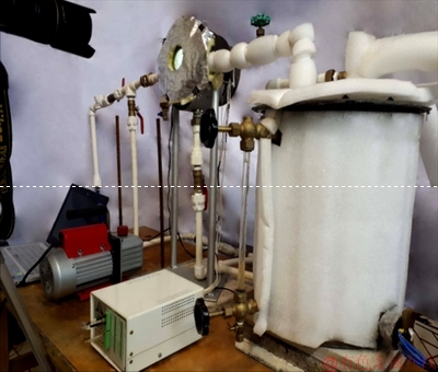
Figure 3 Picture of experimental setup

Figure 4 Different views of specimen (Unit: mm)

Figure 5 Different views of PTFE cover (Unit: mm)
2.3 Data reduction
Assuming that the heat conduction along the specimen is one-dimensional, the heat flux could be predicted by the least squares technique using the measured temperatures. The temperature of the condensing surface can be estimated by employing the given heat flux as follows:
 (3)
(3)
 (4)
(4)
where
 ,
,  (5)
(5)
The HTC can also be computed as follows:
 (6)
(6)
2.4 Uncertainty analysis
The linearization procedure in the preceding section is accurate if temperatures are measured at the center of the base of slots. The tip of a thermocouple may touch the base at any longitudinal positions. It results in a further uncertainty in estimating the heat flux and condensing surface temperature. Supposing that the possible errors have a normal random distribution, the temperature measurement is performed at a single point not in an area; the thermal conductivity is constant along the specimen; the heat transfer is one-dimensional along the specimen; the total error propagation can be approximated as follows [31].
The standard deviation of the temperature measured at each point is:
 (7)
(7)
where STi is the standard deviation of the temperature measured by thermocouples; d is the diameter of the slots; q is the heat flux; k is the thermal conductivity of the specimen.
The standard deviation of the extrapolated temperature of the condensing surface is:
 (8)
(8)
where N is the number of slots (here N=3); xi is the location of the ith slot, and  is the average of slots locations.
The standard deviation of temperature gradient is estimated as follows:
 (9)
(9)
With a given standard deviation of the temperature gradient, the uncertainty of the heat flux calculation can be approximated by regarding the Fourier��s law as follows:
 (10)
(10)
and the uncertainty of the HTC is approximated as follows:
 (11)
(11)
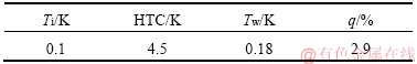
As indicated by KEDZIERSKI et al [31], the temperature gradient and heat flux uncertainty are higher at lower heat fluxes. The maximum uncertainty of the heat flux (supposing heat flux of order 105 W/m2), condensing wall temperature and HTC approximation (supposing the subcooling temperature of 5 K) are given in Table 1.
Table 1 Maximum uncertainty of measured parameters and their propagation into final calculated parameter
2.5 Verification
To check the reliability of the setup, an FWC experiment is performed. The results of HTC are compared with the modified Nusselt theory for a vertical disk developed by O'NEILL et al [32] as follows:
 (12)
(12)
The comparison results are shown in Figure 6. It can be noticed that the difference between the experiment and theory is in the range of 10%.
The emerged discrepancy may be due to changes in environmental conditions or other random errors. Besides, the theory could not exactly estimate all physical details of the problem. For instance, in the theoretical approximation, it is supposed that the condensate layer originates at the upper edge of the disk, uniformly thickens when moving downward, and leaves the surface instantly when approaching the lower edge of the surface. In reality, the surface tension impedes the condensate to leave the surface and the condensate layer becomes thicker than what is approximated by the theory. The thick condensate layer leaves the surface in some moments over the experiment. This thickening and suddenly dripping of the condensate causes that the experiment and theory results become different. Nevertheless, the propagation of the experimental data about the theoretical approximation confirms that no significant systematic errors exist in the setup. Besides, no meaningful deviation can be discovered.

Figure 6 Comparison of current experimental results and results of modified Nusselt theory [32]
3 Results and discussion
3.1 Surface properties
Figure 7 shows the XRD pattern of the sample after the electrodeposition process. The XRD pattern of the sample could be interpreted using the known patterns of some chemical components [33].Three main peaks are at 2��=43.28��, 50.42�� and 74.06��, which belong to the cubic copper phases with orientation planes (111), (200) and (220). This finding indicates that during the electrodeposition process only the dissolved cupric ions deposit on the cathode and no further surface reactions perform. The reddish appearance of the sample after the experiment (Figure 8) also confirms that the coating material is copper.
Figure 9 shows the SEM images of a single-step (Figure 9(a)) and two-step (Figures 9(b)�C(d)) electrodeposition processes. The magnified images are shown in Figure 10. It can be seen that microstructures grow as fern leaf like structures in the single step process (Figure 10(a), the red circle in Figure 9(a)). In the two-step process with low post-processing time (Figure 10(b)), fern-leaf like structures disappear and some random structures emerge. It can be seen that enough void spaces exist among the solid structures. On the other hand, in the two-step process with high post-processing time (Figure 10(c)), most of the void spaces are filled with solid particles.
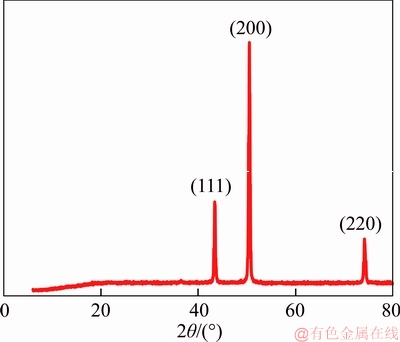
Figure 7 XRD pattern of sample after electrodeposition

Figure 8 Appearance of sample after electrodeposition (a) and bare sample (b)

Figure 9 SEM image:

Figure 10 Magnified image:
3.2 DWC experimental results
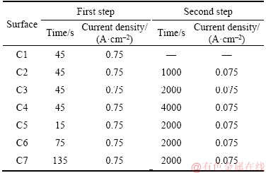
Due to low instability of surfaces prepared by a single-step electrodeposition process, they are not used in the condensation experiments. The conditions used in this study to prepare different surfaces using the two-step electrodeposition are given in Table 2. Three surfaces (C2, C3, C4) with the same first step electrodeposition process(0.75 A/cm2, 45 s), different post processing time, and at a constant current density are examined.
Table 2 Conditions used to prepare micro/nano structured surfaces using two-step electrodeposition process
As shown in Figure 11, the HTC of the surface C4 and the FWC (the smooth surface) are nearly the same. In this condition, as shown in Figure 9(d) the void spaces among the microstructures disappear and the surface behaves like as a smooth surface in the DWC experiment. Therefore, a high post processing time is not proper for DWC purposes, although the surface stability may improve. The HTCs of the samples C2, C3 have nearly the same trends. Both of them have high HTCs at low subcooling temperatures and low HTCs at high subcooling temperatures. The weak performances of these samples in the high subcooling temperature range may be probably due to flooding [34]. It means that at high subcooling temperatures, many droplets nucleate inside the porous structures of the surface, coalesce together and fill up spaces between microstructures. This phenomenon degrades the performance of DWC and closes its heat transfer rate to the FWC heat transfer rate.

Figure 11 Variation of HTC with subcooling temperature for different post-processing time
The surface of C4 has the minimum HTC which is nearly the same as the HTC of FWC. This is because the high post processing time leads to blocking of porous structures created in the first step electrodeposition and converting the surface to a flat surface. These conditions result in emerging big droplets sticking to the surface as shown in Figure 12(a). As the size of droplets increases, the thermal resistance through the droplet increases and the HTC decreases. The effect of the droplet size could be better understood by comparing Figures 12(a) and (b). As well as, previous studies have shown that by increasing droplet size by two times, the heat transfer rate per droplet is reduced by about 60% [35].
Effects of the first step processing time at constant post processing conditions are also investigated as shown in Figure 13. Previous studies have shown that in low electrodeposition duration very sparse micro-nano structures form on the surface. By increasing the processing time, bigger and compact structures form on the surface [36]. As well as, according to Faraday��s law of electrolysis, the mass of the deposited matter on the cathode depends linearly on the process time:
 (13)
(13)
where I is current; t is time; M is the molar mass of copper; z is the valence number of ions of the substance; F is the Faraday constant. In a low deposition time, a small amount of the material deposits on the cathode. Although the thickness of deposited material increases gradually in a longer deposition time duration, but the conduits of the porous coating may be blinded according to the SEM images given in Figure 9. Therefore, by increasing the time of the first step from 15 s to 45 s (surfaces C5 and C3 respectively) the DWC heat transfer increases because porous structures form effectively and the vapor traps in the porous medium. This result helps that a droplet sooner with a smaller radius leaves on the surface. In fact, the trapped vapor reduces the vapor-substrate interface and droplet easily slips on the surface. Smaller droplets have a lower thermal conduction resistance which is the major part of the total thermal resistance of the droplet.

Figure 12 Images of DWC on surface C4 (a) and surface C2 (b)

Figure 13 Effects of first step processing time on dropwise condensation
As said before, increasing electrodeposition time could blind some conduits of the porous medium or increase the amount of the trapped vapor beneath the droplet. Both of the mentioned phenomena weaken the DWC heat transfer rate. The exaggerated conditions of droplets in low and high electrodeposition times are given in Figures 14(a) and (b). It can be seen that a significant part of the substrate beneath the droplet in the high electrodeposition time is filled with trapped vapor, which has very low thermal conductivity with respect to the substrate (copper in this experiment). This result reduces the effective thermal conductivity of the substrate and decreases the heat transfer rate. The variation of the HTC between surfaces C3, C6 and C7 can be interpreted by the conditions shown in Figure 14. It can be seen that some conduits emerged in lower electrodeposition times are closed in a longer time. The vapor/air trapped in these conduits reduces the effective thermal conductivity of the surface and the heat transfer degrades.

Figure 14 Exaggerated conditions of a droplet in high electrodeposition time (a) and low electrodeposition time (b)
4 Conclusions
Condensation is an important regime of heat transfer which has very wide applications in different industries. Condensation appears as FWC or DWC. DWC has a much higher heat transfer with respect to FWC and occurs on hydrophobic and superhydrophobic surfaces. In this study, a two-step electrodeposition process is used to produce the micro/nano structures which are necessary for fabricating hydrophobicity. Different surfaces with various first step or second step electrodeposition conditions are examined. The results show that the DWC heat transfer rate depends on the electrodeposition parameters. It is revealed that the electrodeposition parameters like the time of the process determine the density and distribution of micro/nano structures which deeply affect the heat transfer. The results show that lengthening the electrodeposition time does not necessarily improve the DWC heat transfer. For example, a surface prepared with 2000 s second step process time (surface C3) has about 5 times better heat transfer than a surface with 4000 s second step processing time (surface C4) or a bare surface (surface C1) without electrodeposition process.
Nomenclature
F
Faraday constant
g
Gravitational acceleration, m/s2
h
Heat transfer coefficient, W/(K��m2)
I
Current, A
k
Thermal conductivity, W/(m2��K)
M
Molar mass, mole
m
Deposited matter on the electrode, kg
N
Number of temperature measurement holes
q
Heat flux, W/m2
R
Specimen radius, m
S
Standard deviation
T
Temperature, K
t
Time, s
x
Longitudinal distance, m
Z
Valence number of ions
Greek symbols
��
Viscosity, Pa��s
��
Density, kg/m3
��T
Subcooling temperature, K
��
Angle, (��)
Subscripts
g
Gradient
i
ith slot
v
Vapor
l
Liquid
w
Wall
References
[1] SIAVASHI M, JAMALI M. Optimal selection of annulus radius ratio to enhance heat transfer with minimum entropy generation in developing laminar forced convection of water-Al2O3 nanofluid flow [J]. Journal of Central South University, 2017, 24(8): 1850�C1865.
[2] MAHMOODI M, KANDELOUSI S. Kerosene-alumina nanofluid flow and heat transfer for cooling application [J]. Journal of Central South University, 2016, 23(4): 983�C990.
[3] LIU Fan-han, XU Jian-xin, WANG Hua. Numerical method and model for calculating thermal storage time for an annular tube with phase change material [J]. Journal of Central South University, 2017, 24(1): 217�C226.
[4] NI Ming-long, CHEN Ya-ping, DONG Cong, WU Jia-feng. Numerical simulation of heat transfer and flow of cooling air in triangular wavy fin channels [J]. Journal of Central South University, 2014, 21(7): 2759�C2765.
[5] WANG H, TANG L, WU X, DAI W, QIU Y. Fabrication and anti-frosting performance of super hydrophobic coating based on modified nano-sized calcium carbonate and ordinary polyacrylate [J]. Applied Surface Science, 2007, 253(22): 8818�C8824.
[6] LATTHE S S, SUDHAGAR P, DEVADOSS A, KUMAR A M, LIU S, TERASHIMA C, NAKATA K, FUJISHIMA A. A mechanically bendable superhydrophobic steel surface with self-cleaning and corrosion-resistant properties [J]. Journal of Materials Chemistry A, 2015, 3(27): 14263�C14271.
[7] ALI H M, BRIGGS A. A semi-empirical model for free- convection condensation on horizontal pin�Cfin tubes [J]. International Journal of Heat and Mass Transfer, 2015, 81: 157�C166.
[8] ALI H M, BRIGGS A. Condensation of ethylene glycol on pin-fin tubes: Effect of circumferential pin spacing and thickness [J]. Applied Thermal Engineering, 2012, 49: 9�C13.
[9] ALI H M, QASIM M Z. Free convection condensation of steam on horizontal wire wrapped tubes: Effect of wire thermal conductivity, pitch and diameter [J]. Applied Thermal Engineering, 2015, 90: 207�C214.
[10] ALI H, KAMRAN M S, ALI H M, FARUKH F, IMRAN S, WANG H S. Marangoni condensation of steam-ethanol mixtures on a horizontal low-finned tube [J]. Applied Thermal Engineering, 2017, 117: 366�C375.
[11] SCHMIDT E, SCHURIG W, SELLSCHOPP W. Versuche ��ber die kondensation von wasserdampf in film-und tropfenform [J]. Technische Mechanik und Thermodynamik, 1930, 1(2): 53�C63. (in German)
[12] WANG S, YU X, LIANG C, ZHANG Y. Enhanced condensation heat transfer in air-conditioner heat exchanger using superhydrophobic foils [J]. Applied Thermal Engineering, 2018, 137: 758�C766.
[13] QUAN X, CHEN S, LI J, CHENG P. Enhanced dropwise condensation by oil infused nano-grass coatings on outer surface of a horizontal copper tube [J]. International Communications in Heat and Mass Transfer, 2018, 91: 11�C16.
[14] HOENIG S H, BONNER R W. Dropwise condensation on superhydrophobic microporous wick structures [J]. Journal of Heat Transfer, 2018, 140(7): 071501.
[15] WEN R, LI Q, WU J, WU G, WANG W, CHEN Y, MA X, ZHAO D, YANG R. Hydrophobic copper nanowires for enhancing condensation heat transfer [J]. Nano Energy, 2017, 33: 177�C183.
[16] TALESH BAHRAMI H R, AHMADI B, SAFFARI H. Optimal condition for fabricating superhydrophobic copper surfaces with controlled oxidation and modification processes [J]. Materials Letters, 2017, 189(Supplement C): 62�C65.
[17] SAFFARI H, SOHRABI B, NOORI M R, TALESH BAHRAMI H R. Optimal condition for fabricating superhydrophobic aluminum surfaces with controlled anodizing processes [J]. Applied Surface Science, 2018, 435: 1322�C1328.
[18] TALESH BAHRAMI H R, AHMADI B, SAFFARI H. Preparing superhydrophobic copper surfaces with rose petal or lotus leaf property using a simple etching approach [J]. Materials Research Express, 2017, 4(5): 055014.
[19] HE G, LU S, XU W, YU J, WU B, CUI S. Fabrication of durable superhydrophobic electrodeposited tin surfaces with tremella-like structure on copper substrate [J]. Surface and Coatings Technology, 2017, 309: 590�C599.
[20] QING Y, YANG C, YU Z, ZHANG Z, HU Q, LIU C. Large-area fabrication of superhydrophobic zinc surface with reversible wettability switching and anticorrosion [J]. Journal of the Electrochemical Society, 2016, 163(8): D385�CD391.
[21] XU L, GUO Y, LIAO Q, ZHANG J, XU D. Morphological control of ZnO nanostructures by electrodeposition [J]. The Journal of Physical Chemistry B, 2005, 109(28): 13519�C13522.
[22] TALESH BAHRAMI H R, SAFFARI H. Theoretical study of stable dropwise condensation on an inclined micro/nano- structured tube [J]. International Journal of Refrigeration, 2017, 75(Supplement C): 141�C154.
[23] ELIAS J, TENA-ZAERA R, L VY-CLMENT C. Electrodeposition of ZnO nanowires with controlled dimensions for photovoltaic applications: Role of buffer layer [J]. Thin Solid Films, 2007, 515(24): 8553�C8557.
[24] BAHRAMI H R T, SAFFARI H, BAHRAMI H R T, SAFFARI H. Mathematical modeling and numerical simulation of dropwise condensation on an inclined circular tube [J]. Journal of Aerospace Technology and Management, 2017, 9(4): 476�C488.
[25] PATIL C M, SANTHANAM K S V, KANDLIKAR S G. Development of a two-step electrodeposition process for enhancing pool boiling [J]. International Journal of Heat and Mass Transfer, 2014, 79: 989�C1001.
[26] GAO J, LU L S, SUN J W, LIU X K, TANG B. Enhanced boiling performance of a nanoporous copper surface by electrodeposition and heat treatment [J]. Heat and Mass Transfer, 2017, 53(3): 947�C958.
[27] ALBERTSON C E. Boiling heat transfer surface and method: US4018264A [P]. 1977-04-19.
[28] KIM J H. Enhancement of pool boiling heat transfer using thermally-conductive microporous coating techniques [D]. Arlington: University of Texas, 2006.
[29] EL-GENK M S, ALI A F. Enhanced nucleate boiling on copper micro-porous surfaces [J]. International Journal of Multiphase Flow, 2010, 36(10): 780�C792.
[30] SAMOYLOV A V, MIRSKY V M, HAO Q, SWART C, SHIRSHOV Y M, WOLFBEIS O S. Nanometer-thick SPR sensor for gaseous HCl [J]. Sensors and Actuators B: Chemical, 2005, 106(1): 369�C372.
[31] KEDZIERSKI M A, III J L W. Design and machining of copper specimens with micro holes for accurate heat transfer measurements [J]. Experimental Heat Transfer, 1993, 6(4): 329�C344.
[32] O��NEILL G A, WESTWATER J W. Dropwise condensation of steam on electroplated silver surfaces [J]. International Journal of Heat and Mass Transfer, 1984, 27(9): 1539�C1549.
[33] GUO Y, WU H, LI Y, JIANG C, WANG Q, WANG T. Facile fabrication of superhydrophobic Cu(OH)2 nanorod and CuO nanosheet arrays on copper surface [J]. Journal of Nanoscience and Nanotechnology, 2012, 12(3): 1952�C1956.
[34] SABLOWSKI J, UNZ S, BECKMANN M. Dropwise condensation on advanced functional surfaces�Ctheory and experimental set-up [J]. Chemical Engineering & Technology, 2017, 40(11): 1966�C1974.
[35] KIM S, KIM K J. Dropwise condensation modeling suitable for superhydrophobic surfaces [J]. Journal of Heat Transfer, 2011, 133(8): 081502.
[36] XI J, FENG L, JIANG L. A general approach for fabrication of superhydrophobic and superamphiphobic surfaces [J]. Applied Physics Letters, 2008, 92(5): 053102.
(Edited by YANG Hua)
���ĵ���
���������/���ṹ����ĵ�״�������ȴ���
ժҪ��������һ����Ҫ�Ĵ��Ȼ��ƣ��ڷ��糧����ů��ͨ�硢�յ����������ҵ���Ź㷺��Ӧ�á����������ֲ�ͬ��ģʽ����������Ĥ״����(FWC)�͵�״����(DWC)������ˮ�ͳ���ˮ�����Ϸ����ĵ�״�����ȴ�������Զ����Ĥ״��������ˣ��������Ե�״���������˹㷺���о�������ˮ������еͱ����ܵ����ṹ���ڱ��о��У������������������ͭ���������/���ṹ�����Ҵ���1-ʮ������Һ����װ�����Ӳ������������ı����ܡ������������������վ�����ѵ����������磬���ڶ��������ʱ��Ϊ2000 sʱ����״�������ȴ�������Ĥ״������5���������ڶ��������ʱ��Ϊ4000 sʱ����״����(DWC)��Ĥ״����(FWC)�ȴ��ݼ�����ͬ��ʹ��XRD��SEM��������Ʊ����������档SEM������ʾ�������������ϴ���һЩ�ṹ��ͨ���ӳ��ڶ��������ʱ�䣬���Խ��ͱ����϶�ʡ�
�ؼ��ʣ��������ȴ��ݣ��������/���ṹ����϶��
Received date: 2018-08-16; Accepted date: 2018-09-23
Corresponding author: Hamid SAFFARI, PhD, Associate Professor; Tel: +98-21-77240391; E-mail: saffari@iust.ac.ir; ORCID: 0000-0002-1941-6271

