J. Cent. South Univ. Technol. (2007)06-0820-06
DOI: 10.1007/s11771-007-0156-3

Concentrated and gastight sampling technique of deepsea microplankton
HUANG Zhong-hua(���л�)1, LIU Shao-jun(���پ�)1, JIN Bo(�� ��)2, LI Li(�� ��)1, CHEN Ying(�� ӥ)2
(1. School of Mechanical and Electrical Engineering, Central South University, Changsha 410083, China;
2. National Key Laboratory of Fluid Power Transmission and Control, Zhejiang University, Hangzhou 310027, China)
Abstract: A new sampling method of deepsea microplankton with function of in-situ concentrated sampling and gastight sampling was proposed. In-situ concentrated sampling technique was realized as follows: a microplankton membrane was used as filtration membrane, and a deepsea pump was used to pump seawater; the microplankton was captured and the density of microplankton was increased when seawater flow through the filtration membrane. Gastight sampling technique was realized as follows: a precharged accumulator was used as pressure compensator. During the process of lifting the sampler, the accumulator compensated the pressure drop continuously. The laboratory experimental results show that with in-situ concentrated sampling technique, in-situ concentrated sampling can be realized and the maximum concentration ratio reaches up to 500. With pressure compensation technique based on accumulator, gastight sampling can be realized. When sampling at 6 km and the precharge pressure of accumulator is 18 MPa, pressure drop of the sample is less than 2% compared with its original pressure. Deepsea experiment (at 1.9 km) results show that the sampler can realize in-situ concentrated sampling and gastight sampling.
Key words: sampler; concentrated sampling; gastight sampling; deepsea microplankton
1 Introduction
Deepsea microplankton is a kind of new deepsea resource discovered lately, which lives in deepsea of several thousands meters and can survive and multiply in conditions of strong acid or strong base, low temperature, high salt and high pressure[1-2]. Scientific research results show that deepsea microplanktons have many important characteristics. They can decompose petroleum, which can be applied in environment protection. They have important role in deepsea gas hydrate forming[3]. They may be the constructor of deepsea manganese nodule and can abstract metals from manganese nodule and polymetallic nodule[4]. Compared with land microplankton, they may have different metabolize way and heredity background[5].
Research of deepsea microplankton is useful to find out the origin of earth being, discover new gene and develop new medicine. Researches in America, Japan and some European countries on deepsea microplankton have studied for decades and many deepsea microplankton samplers have been produced[6-8]. For the density of deepsea microplankton is very low and the sampling depth is several thousands meters, there some limitations on traditional samplers, such as the sampler can only obtain small samples with single sampling and the samples cannot keep their original pressure.
A new type of deepsea microplankton sampler was designed in this paper, which can obtain large quantity of samples with single sampling and keep the samples with their original pressure.
2 Structure and working principle of sampler
The structure of in-situ concentrated and gastight sampler of deepsea microplankton is shown in Fig.1. The sampler is composed of pump, filter membrane, sampling vessel, accumulator, check valve, solenoid check valve and manometer. The pump is used for pumping seawater flow through filter membrane; the filter membrane is used for capturing deepsea microplankton; the sampling vessel is used for sample storage; the check valve and solenoid check valve are used for closing the sampling vessel when sampling is over; the accumulator is used for pressure compensation and the controller is used for On/Off control of the pump and the solenoid check valve.
The working principle of the sampler is as follows: the sampling vessel is filled with distilled water and the accumulator is precharged with N2 before sampling. The sampling depth is preset in the controller. During the drop process of the sampler, the controller will check environmental pressure real-time. When the sampler reaches the set sampling position, the controller will generate a trigger to start the pump and the solenoid check valve. With the control of the flow-through time, sampling with fixed concentration ratio will be available. When the sampling process is over, the controller will shut the pump and the solenoid check valve. During the lifting process of the sampler, the environmental pressure will decrease and the volume of the sampling vessel will increase, which will cause pressure drop of the samples. With real-time pressure compensation, the samples can keep its original pressure.
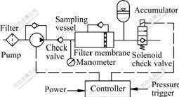
Fig.1 Structure of concentrated and gastight sampler of deep-sea microplankton
Two working modes are designed for the sampler in order to improve the serviceable range. One is automatic control sampling, and the other is controlled by submarine. The difference between the two working modes is the former needs to carry power by itself and the sampling trigger is generated with real-time pressure check of the environment, and the later gets power and sampling trigger from submarine; in the former working mode, the maximum sampling depth is limited by the sampler; in the later working mode, the maximum sampling depth is limited by the maximum working depth of the submarine [9].
3 In-situ concentrated sampling technique
The density of deepsea microplankton is about 1��104-1��106/mL. It is very low compared with that of land microplankton. Sample translation and concentration are the first step of laboratory study, which may causes sample lost during the concentration and sample death during the translation. An ideal solution is to concentrate sample at the sampling position. By this way, the sample can be studied in laboratory directly without additional concentration.
The working principle of in-situ concentrated sampling is as follows: when the pump pumps seawater flow through the filter membrane with optional aperture, the microplankton will be captured by the filter membrane and the density of microplankton in the sampling vessel will be increased.
Supposing that the time of flow through is t, the output pressure of pump is pd, the output flow is qd, the flow resistance of filter membrane is pr, the maximum flow of filter membrane is qVmax, the volume of sampling vessel is Vt. The necessary conditions of in-situ concentrated sampling are as follows:
 (1)
(1)
The concentration ratio �� is defined as follows:
 (2)
(2)
In Eqn.(1), the output pressure and output flow of pump can be measured accurately with experiment, but the flow resistance of filter membrane is related with the quantity and the volume of microplankton, which is random and only the statistic value can be obtained with experiment. According to the demand of project, aperture of the filter membrane is 0.45 ��m and diameter of the filter membrane is 45 mm. Massive experiments were carried out to get the statistic value of the flow resistance of the filter membrane. The experimental results are shown in Fig.2, which indicates the relationship of the flow resistance of the filter membrane and the flow flux of filter membrane. From Fig.2 the following conclusions can be drawn: the flow resistance and the flow flux of the filter membrane almost kept constant in 30 min. The flow resistance is about 95 kPa and the flow flux is about 0.23 m3/h.

Fig.2 Relationship between flow resistance (pr), flow flux (qVmax) of filter membrane and flow time
To get accurate density of deepsea microplankton at the sampling position, accurate control of concentration ratio is needed. Close-loop control of flow is a way to get accurate concentration ratio of deepsea microplankton. In this study, the concentration ratio is determined by the control of flow time, which is an open-loop control in nature. The considerations of the solution are as follows: the sampling position is random, and it is useless to improve the precision of the concentration ratio at one sampling position which cannot represent the statistical distribution of the sampling area. In fact, the error caused by open-loop control of flow can be decreased with long time of flow-through. At the same time, close-loop control and measurement of flow will increase the cost and complexity of the sampler.
In Fig.1, the pump and the solenoid check valve are key components to realize in-situ concentrated sampling. They should have the quality of working at 60 MPa. At the same time, a reliable microcontroller with low consumed power is needed. In this study, a microcontroller based on singlechip of msp430 and the corresponding airtight cabin are designed.
In Fig.1, the output pressure and output flow of pump are unstable. In order to obtain stable output pressure and output flow, experiments on mounting position and open sequence of the pump and the solenoid valve are carried out. The experimental results show that it is likely to obtain more stable output pressure and output flow when the pump is mounted in front of the sampling vessel and open the solenoid check valve prior to the pump.
4 Sealing technique of high-pressure seawater hydraulic system
The sampler is a typical high-pressure seawater hydraulic system. In order to realize gastight sampling, reliable sealing design is necessary. For seawater is corrosive, the sealing components must be resistant material. Rubber is an ideal resistant material with low price. For the sealing pressure is very high, double-sealing design is used in the sealing of lid and base, which is shown in Fig.3.
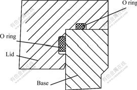
Fig.3 Structure of double-sealing design
The predecrement of the O ring is very important on the sealing performance. If the predecrement of the O ring is not enough, seawater will immerse the sealing cabin during the process of pressure increase, and if the predecrement of the O ring is excessive, the O ring may be destroyed on mounting. Research on the relationship of the sealing performance of the O ring and predecrement of the O ring were carried out based on FEA (finite element analysis method)[10-13]. The research results are shown in Fig.4. From Fig.4, the following conclusions can be obtained: with the increase of predecrement, the effective sealing stress increases correspondingly. When the predecrement of the O ring is less than 1 mm, the increase of predecrement can improve the sealing performance; when the predecrement of the O ring is greater than 1 mm, the increase of predecrement cannot improve the sealing performance. So in practice, the optimal predecrement of the O ring is 1mm. The results of sealing performance experiment at 60 MPa show that the conclusion is correct.

Fig.4 Relationship between sealing performance and predecrement
5 Pressure compensation technique based on accumulator
During the lift process of sampler, the vessel volume of sampler increases because the environmental pressure is decreased. At the same time, microleakage may exist in the sealing band of the sampling vessel, which will cause pressure drop of the sample and change the physical status of the sample. To realize gastight sampling, effective pressure compensation methods are necessary. Accumulator is chosen as pressure compensation device for its great pressure compensation volume and low price. The pressure compensation result is related closely with the volume and precharge pressure of accumulator.
The sampler is put into freezing room quickly after the sampler reaches the deck. So the pressure change of the sample caused by temperature change is minute and can be ignored[14].
Supposing that the inner radius of the sampling vessel is ri, the outside radius of the sampling vessel is re, the height of the sampling vessel is h, seawater pressure at the sampling position is ps, final pressure of sample in the vessel is pf, the elastic module of sampling vessel is E, Poisson ratio of sampling vessel is ��, nominal volume of accumulator is Va0, precharge pressure of the accumulator is pa0, volume at the sampling position is Vas, volume at the end of sampling is Vaf, total leakage of the sampling vessel is ��Vt, the axial deformation of the sampling vessel ��h at the end of sampling is
 �� �� (3)
Radial deformation ��r is
 (4)
(4)
Total cubic deformation ��V is
 (5)
(5)
Considering the sampling time is long (longer than 2 h when the sampling depth is 6 km) and the environmental temperature is almost the same, it is reasonable to assume that the gas in the accumulator undergoes an isothermal process, and the gas status equations of the process are as follows[15]:
Drop process
 (6)
(6)
Lift process
 (7)
(7)
The volume of compensation of the accumulator ��Vb is
 (8)
(8)
According to demand of gastight sampling, the pressure drop of sample should be less than 10% compared with its original pressure, that is,
 (9)
(9)
From Eqns.(5), (8) and (9), the following equation can be obtained,
 (10)
(10)
In this study, the values of parameters in Eqn.10 are as follows: h=0.1 m, ps=60 MPa, Va0=0.63 L, E=100 GPa, ��=0.4, ri=5.2 cm��re=6.7 cm.
The relationship between the final pressure of sample and the precharge pressure of accumulator is shown in Fig.5, which shows that with the increase of precharge pressure of accumulator, the final pressure of sample increases obviously. When the precharge pressure of accumulator is larger than 14 MPa, pressure drop of sample will be less than 10%; when the precharge pressure of accumulator is 18 MPa, pressure drop of sample will be less than 2%; when the precharge pressure of accumulator is greater than 20 MPa, the final pressure of sample almost keeps the same. So in practice, excessive precharge pressure of accumulator is unnecessary. When the sampling depth is 6 km, the optimal precharge pressure is 18 MPa.
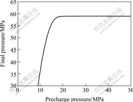
Fig.5 Relationship of final pressure of sample and precharge pressure of accumulator
The relationship between the final pressure of sample and the nominal volume of accumulator is shown in Fig.6, which shows that with the increase of nominal volume of accumulator, the final pressure of sample increases correspondingly. When the nominal volume of accumulator is less than 0.6 L, increasing the nominal volume of accumulator can increase the final pressure of sample obviously. When the nominal volume of accumulator is greater than 0.6 L, the final pressure of sample almost keeps the same. At the same time, when the nominal volume of accumulator is greater than 0.6 L, the mass of the sampler will increase obviously compared with that of 0.6 L. So in practice, the nominal volume of accumulator is limited by the mass requirement of the sampler.
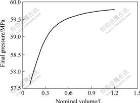
Fig.6 Relationship of final pressure of sample and nominal volume of accumulator
6 Laboratory experiment
Considering that the cost of deepsea experiment is expensive, massive laboratory experiments were carried out to test the performance of sampler. Controllable high pressure cabin is the key device of laboratory experiments. The maximum pressure of the high pressure cabin used in this study is 70 MPa.
The laboratory experiments include three parts, the first is pressure-resistance test of key components, the second is gastight sampling performance test of sampling vessel based on accumulator, and the third is concentrated sampling performance test of sampler.
Experimental results of pressure-resistance of key components at 70 MPa show that the pump, the solenoid check valve, the controller and the sampling vessel can work reliably.
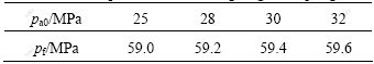
The experimental process of gastight sampling performance of sampling vessel based on accumulator is as follows, the sampling vessel connected with accumulator is put into the high pressure cabin, and the pressure of cabin is increased at speed of 1 MPa/min. When the pressure is equal to 60 MPa, the pressure is kept for 20 min, then the pressure is decreased at speed of 1 MPa/min till to ordinary pressure. The experimental results are shown in Table 1, which shows that when the precharge pressure of accumulator is greater than 25 MPa, the pressure drop of sample is less than 2%, indicating that accumulator is an effective pressure compensation device.
The experimental process of concentrated sampling of the sampler is follows. A pressure signal is given to trigger the sampling process, and then check whether the pump and solenoid check valve of the sampler can open with designed sequence. The experimental results show that when the sampling trigger is given, the sampler can work with designed sequence properly.
Table 1 Experiment results of gastight sampling
7 Deepsea experiments
The performance of sampler was tested at China south sea in 2004. For the maximum depth of experiment area is 2.0 km, the test depth of sampler is 1.9 km. The performance of sampler was tested for twice. At the first time, the precharge pressure of accumulator was 8.0 MPa, and the final pressure of sample was 18.6 MPa. At the second time, the precharge pressure of accumulator was 10.0 MPa, and the final pressure of sample was 19.0 MPa. The experimental results show that by using accumulator as pressure compensation device, the sampler can realize gastight sampling reliably and with the precharge pressure of accumulator increase, the final pressure of sample will increase corresponding.
Fig.7 shows the deepsea experiment curve of water depth and working status of pump, which shows that the sampler works with designed sequence properly.
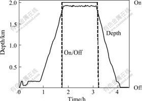
Fig.7 Deepsea experiment curve of the sampler
8 Conclusions
1) A new sampling method is proposed to realize in-situ concentrated sampling, which uses a pump to pump seawater flow through a filter membrane and can increase the density of microplankton obviously.
2) Gastight sampling is realized by using precharged accumulator as pressure compensation device, and the relationship among the precharge pressure and nominal volume of accumulator and final pressure of sample are studied in detail.
3) Experiment results show that in-situ concentrated sampling and gastight sampling of deepsea microplankton is feasible.
References
[1] CHEN Xiu-lan, ZHANG Yu-zhong, GAO Pei-ji. Progress in deepsea microbiology[J]. Marine Sciences, 2004, 28(1): 62-67. (in Chinese)
[2] LI Shi-lun, ZHANG Jian-wen, YE Shu-ming, et al. Temperature control system for the simulation platform of culturing deepsea microbes[J]. Ocean Engineering, 2004, 22(3): 92-96. (in Chinese)
[3] XIAO Tian, CHEN Ma. Microbial processes at deep sea hydrothermal vents[J]. Marine Sciences, 1998, 22(6): 11-15. (in Chinese)
[4] HU Wen-xuan, ZHOU Huai-yan, GU Liang-xin. New proof on microbe formed deepsea manganese nodule[J]. China Science (D Edition), 1999, 29(4): 362-368. (in Chinese)
[5] XI Feng, ZHENG Tian-ling, JIAO Nian-zhi, et al. A preliminary analysis of mechanism of deep sea microorganisms diversity[J]. Advance in Earth Sciences, 2004, 19(1): 38-46. (in Chinese)
[6] JACOBS P H. A new rechargeable dialysis pore water sampler for monitoring sub-aqueous in-situ sediment caps[J]. Water Research, 2002, 36: 3121-3129.
[7] DIMEO C A, WAKEFIELD J R, CRAIG C S. A new device for sampling small volumes of water from marine micro-environments[J]. Deep-Sea Research I, 1999, 46: 1279-1287.
[8] BIANCHI A, GARCIN J, THOLOSAN O. A high-pressure serial sampler to measure microbial activity in the deep sea[J]. Deep-Sea Research I, 1999, 46: 2129-2142.
[9] HUANG Zhong-hua, LIU Shao-jun, SHEN Hai-kuo, et al. Control system design of autonomic deepsea plankton sampler with concentrated and fidelity function[J]. Ocean Engineering, 2006, 24(1): 128-131. (in Chinese)
[10] GADALA M S. Recent advances in the numerical modeling of constitutive relations[J]. Finite Elements in Analysis and Design, 1997, 24(3): 171-185.
[11] SHANGGUAN Wen-bin, LU Zhen-hua. Modelling of a hydraulic engine mount with fluid�Cstructure interaction finite element analysis[J]. Journal of Sound and Vibration, 2004, 5(1): 193-221.
[12] HUSNU D M��ESRA A. Computer aided modelling of flexible forming process[J]. Journal of Materials Processing Technology, 2004, 148(3): 376-381.
[13] BANKS H T��PINTER G A, YEOH O H. Analysis of bonded elastic blocks[J]. Mathematical and Computer Modelling, 2002, 36(7): 875-888.
[14] HUANG Zhong-hua, JIN Bo, LIU Shao-jun, et al. Quick plenum process of bladder accumulator[J]. Journal of Central South University: Science and Technology, 2006, 37(2): 306-309. (in Chinese)
[15] HUANG Zhong-hua, LIU Shao-jun, JIN Bo. Isobaric technique based on accumulator for deepsea microbe sampling[J]. China Ocean Engineering, 2006, 20(2): 335-342.
(Edited by CHEN Wei-ping)
Foundation item: Project(DY105-03-01-10) supported by China Ocean Mineral Resources Research and Development Association; Project (1343-75221) supported by Central South University
Received date: 2007-03-02; Accepted date: 2007-04-18
Corresponding author: HUANG Zhong-hua, PhD; Tel: +86-738-8830245; E-mail: csu707@163.com

