Pressure performance improvement by dual-mode control in digital pump/motor
��Դ�ڿ������ϴ�ѧѧ��(Ӣ�İ�)2020���9��
�������ߣ���� ����� �ˬ �뺣�� ������
����ҳ�룺2628 - 2642
Key words��digital hydraulic; dual-mode operating characteristics; AMESim simulation; TOPSIS algorithm
Abstract: Due to the advantages of low cost, fast response and pollution resistance, digital hydraulic pump/motor can replace conventional variable hydraulic pump/motor in many application fields. However, digital hydraulic components produce large hydraulic impact at variable moments, which will shorten the service life of mechanical components. Through the simulation analysis of the variable process of digital pump/motor, it is found that the discontinuous flow caused by displacement step changes is the fundamental cause of hydraulic impact. The data analysis results of experimental tests are in good agreement with the simulation analysis results. In view of hydraulic secondary components, a variable control method based on dual-mode operating characteristics is proposed. The TOPSIS algorithm is used to give comprehensive evaluation of the displacement control results after this method. The results show that the control quality of digital pump/motor after adopting the control method has been effectively improved, with an average improvement of about 40%.
Cite this article as: LI Chun-shuang, WANG Xin, QI Hai-bo, LIU Xin-yu, LIU Xin-hui. Pressure performance improvement by dual-mode control in digital pump/motor [J]. Journal of Central South University, 2020, 27(9): 2628-2642. DOI: https://doi.org/10.1007/s11771-020-4487-7.

J. Cent. South Univ. (2020) 27: 2628-2642
DOI: https://doi.org/10.1007/s11771-020-4487-7

LI Chun-shuang(�ˬ)1, WANG Xin(���)1, 2, QI Hai-bo(�뺣��)1,LIU Xin-yu(������)2, LIU Xin-hui(�����)1
1. School of Mechanical and Aerospace Engineering, Jilin University, Changchun 130022, China;
2. Department of Mechanical and Industrial Engineering, University of Toronto, Toronto M5S 2E8, Canada
 Central South University Press and Springer-Verlag GmbH Germany, part of Springer Nature 2020
Abstract: Due to the advantages of low cost, fast response and pollution resistance, digital hydraulic pump/motor can replace conventional variable hydraulic pump/motor in many application fields. However, digital hydraulic components produce large hydraulic impact at variable moments, which will shorten the service life of mechanical components. Through the simulation analysis of the variable process of digital pump/motor, it is found that the discontinuous flow caused by displacement step changes is the fundamental cause of hydraulic impact. The data analysis results of experimental tests are in good agreement with the simulation analysis results. In view of hydraulic secondary components, a variable control method based on dual-mode operating characteristics is proposed. The TOPSIS algorithm is used to give comprehensive evaluation of the displacement control results after this method. The results show that the control quality of digital pump/motor after adopting the control method has been effectively improved, with an average improvement of about 40%.
Key words: digital hydraulic; dual-mode operating characteristics; AMESim simulation; TOPSIS algorithm
Cite this article as: LI Chun-shuang, WANG Xin, QI Hai-bo, LIU Xin-yu, LIU Xin-hui. Pressure performance improvement by dual-mode control in digital pump/motor [J]. Journal of Central South University, 2020, 27(9): 2628-2642. DOI: https://doi.org/10.1007/s11771-020-4487-7.
1 Introduction
Compared with the traditional transmission scheme, hydraulic transmission has an incomparable advantage of high-power density [1]. However, many commercial products don��t use hydraulic system because it is inefficient and difficult to control under partial load (light load/ low displacement). Digital hydraulic is a new technology that obtains system variable outputs through real-time control of discrete hydraulic components [2]. Compared with traditional hydraulic variable control, digital hydraulic has the advantages of low cost, high response, easy control and high efficiency [3-6], which has received extensive attention in the hydraulic industry in recent years [7-9], and has been applied in large-scale equipments such as loaders [10] and excavators [11, 12].
Due to the advantages of digital hydraulic, scholars in various fields have carried out research at this stage. In August 2010, more than 100 scholars from all over the world gathered together in the third digital hydraulic seminar, which showed the growing interest in digital hydraulic technology. Digital hydraulic has two basic branches,parallel digital hydraulic technology and high speed switching digital hydraulic technology.
High speed switching digital hydraulic technology can achieve high efficiency by using high-speed continuous switch or adjusting pulse width ratio, with one valve or more [2]. But there is a large amount of parasitic power in the process of high-speed switching of the actual system, which leads to the decrease of efficiency [13]. VICTOR et al [14] studied the influence of pulse width modulation (PWM) control method, liquid resistance, liquid volume, inertia of control elements and flow on the quality of output pressure control under constant pressure system. RAINER et al [15] used accumulator and damper to form RC low-pass filter of high-speed on-off valve control loop, which smoothed the pressure fluctuation and impact caused by switching of on-off valve and load fluctuation. The speed fluctuation caused by high-speed on-off valve can be reduced by improving the switching frequency or increasing the system inertia or damping, but at present the large number of frequent switching times (50 Hz) make this technology not suitable for the system requiring long-term continuous operation.
In this regard, the parallel digital hydraulic technology realizes active control through logical combination of hydraulic components without relying on the high-speed switching performance of the control valve, which has lower requirements on system hardware and better performance in energy efficiency and reliability. In 1984, MOORHEAD et al [16] and ZHANG et al [17] first put forward the idea of combining sequence variables. As several high-duty gear pumps are connected with a low-duty variable pump, accurate flow control can be realized through the combination of high-duty pumps and fine adjustment of low-duty pump. In 2011, MATTI [2] proposed a digital flow control unit (DFCU) composed of multiple parallel switch valves with different flow areas. Its flow area is the sum of the open flow areas, and the flow is controlled by the combination of control valves. In the same year, LIU et al [18] proposed a step variable displacement (SVD) system composed of a quantitative pump/motor, which is also a parallel digital hydraulic system. Taking the smallest displacement as the highest accuracy in fitting the displacement, it realizes the step adjustment of the output displacement through the logic control of the switch valve matrix. It boasts the advantages of strong self-priming capability, low price, high reliability and strong anti-jamming capability [19]. HEITZIG et al [20] proposed a kind of digital pump with binary combination, and simulated its efficiency, accuracy and switching frequency. In the next year, it was proved that the digital pump had more advantages in energy saving than the conventional pump control system in partial load condition of the multi actuator system [21]. In 2019, MIIKKA et al [22] made a digital transformation of the working device hydraulic system on the wheel excavator, and compared the original load sensitive system with the digital valve controlled hydraulic cylinder system in the aspect of the inlet and outlet regulation. The experiment showed that under the specific cycle conditions the energy input of the digital valve control system can be reduced by 36%. But they also pointed out that how to reduce the perceptible unsmoothness in the flow changing process is of great importance.
In parallel digital hydraulic control, the sudden change of displacement will cause phenomena like hydraulic impact in pipelines and chattering of the system, which may deteriorate the control quality. In high-power equipment, the impacts of hydraulic pressure and torque will also exert a great effect on the service life and reliability of the system. Therefore, it is one of the key issues to suppress pressure impact and maintain system stability in the research of step variable control.
LAAMANEN et al [23, 24] studied the pressure impact of digital pump, and proposed that Fibonacci code not only improved the flow and pressure shock, but also reduced the switching times, and successfully applied the digital flow control system to the dust removal of rock drill. HEIKKILA et al [25] proposed semi-active throttling and active pressure compensation control for the low damping characteristics of the digital pump control system, which had a restraining effect on the velocity shock under the step excitation of the system. In 2016, WANG et al [26] proposed a step timing control strategy according to the mechanism of variable impact of digital hydraulic pump/motor, which can effectively reduce torque impact by about 23%. In 2017, YAO et al [27] and ZHANG et al [28] proposed a time difference delay control strategy for the flow shock existing in the state switching of pump group in multi pump system, which reduced the impact partially. However, due to the limited number of combined units, control quality is restricted by the minimum displacement, especially when the high-duty system is required. Reducing the minimum combined displacement is an effective method to reduce impact.
Hydraulic pump/motor, the so-called secondary component, commonly used in hydraulic hybrid power system, is a hydraulic component that can work in two modes [29, 30]. According to the system operation, it can work in either motor mode or pump mode [31, 32]. The control valve group is used to change the working mode of the digital pump/motor and the mechanical-hydraulic energy is distributed and converted within a collection of units, so that part of the combined displacement can be ��subtracted�� in the variable process. Compared with the ��on-off�� two-state of conventional parallel digital hydraulic system, the displacement operation rules of the dual-mode digital hydraulic pump/ motor system have three states of ��positive-zero- negative��, which greatly increases the combination modes of displacement. This combination method based on dual-mode operating characteristics can realize smaller variable steps, i.e. higher variable control accuracy, with the same number of combination units. Or it can use fewer combined units to achieve the same displacement adjustment range, which has obvious effects on the reduction of variable pressure impact and the simplification of digital components as well as their control valve groups.
Comparing with the literatures that have been studied, the main contributions of this study are highlighted as follows: 1) In order to overcome the pressure and torque shock in the process of displacement change, a dual-mode control method with forward and reverse torque compensation is proposed; 2) The pressure model of dual-mode control method with forward and reverse torque compensation is established; 3) Combination method of theoretical analysis, dynamic simulation and experimental research are used to deeply analyze the effect of the dual-mode working mode on the control characteristics; 4) The evaluation indexes of digital hydraulic pump/motor control characteristics are made clear. Meanwhile, technique for order preference by similarity to ideal solution (TOPSIS) algorithm is used to evaluate the displacement control results of the dual-mode method, and thus a reference is provided for the control of the digital pump/motor. The rest of this paper is organized as follows. Section 2 briefly introduces the principle of traditional single mode digital system and the pressure model, and builds a simulation model to analyze the reason of pressure and torque shock combined with experiments. Section 3 introduces and studies dual-mode control method. Section 4 focuses on evaluation of optimization results and some concluding remarks are shown in Section 5.
2 Analysis of single-mode digital pump/ motor system
2.1 Principle of single-mode digital pump/motor system
In the conventional digital pump/motor system, the digital pump/motor is merely used as a single-mode operation of the hydraulic pump (hereinafter referred to as the single mode). The combination form of the hydraulic pump in the system operation is controlled through the arrangement of different combination states of the switch valve, so as to realize the step change of the displacement. As shown in Figures 1 and 2, there are schematic diagrams of two conventional digital pump/motor systems [2, 18].
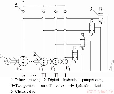
Figure 1 Mechanism of single mode SVD pump/motor:
If the displacement of each step is Vi, when working in the single mode, there are:
 (1)
(1)
where Vi is the displacement of each unit of the digital pump/motor, mL/r; V is the working displacement of the digital pump/motor, mL/r; n is the number of units; ai represents the working state of the digital pump/motor; when in pump mode, ai=1; when in unloaded mode, ai=0; bi is the proportion coefficient of the equal ratio combination unit. In order to keep the displacement fitting accuracy unchanged, the geometric progression with bi=2 is taken, and then Vi+1=2Vi, and Vn=2n-1 can be obtained. It can be seen that the working displacement should be taken within the range of 0 to (2n-1)V1, with the resolution being V1, and the number of achievable displacements being 2n.
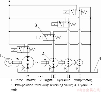
Figure 2 Mechanism of single mode SVD pump/motor:
2.2 Mechanism analysis of hydraulic impact
For ease of analysis, a two-unit digital pump/motor is taken as an example to analyze the speed control loop with constant load. The pipeline from the oil pressure chamber of the hydraulic pump to the valve port of the reversing valve forms the first closed chamber. The inner wall surface of the pipeline from the valve port of the directional valve to the hydraulic cylinder and the actuator chamber form the second dynamic closed chamber, where the pressures are all equal. The situation of the combined units entering different working states from unloading is analyzed.
Assuming that the oil temperature is constant, according to the compressibility of the fluid, then:
 (2)
(2)
where V0 represents initial volume of oil in dynamic closed chamber, L; ��e is the volume elasticity modulus of oil, MPa; ��V denotes the changes in oil volume, L; ��p represents the variation of the pressure in the pipeline chamber, MPa.
Differentiating the equation, the expression of compressible flow rate ��q is obtained:
 (3)
(3)
which can be deformed to obtain the expression of pressure variation:
 (4)
(4)
The incremental expression can be overwritten as:
 (5)
(5)
where ��q represents the difference between the flow rate in and out of the dynamic closed chamber within time ��t, L/s.
It can be seen that the difference in liquid flow rate in and out of the dynamic closed chamber is the cause of pressure impact.
In view of the influence of pump leakage and oil compression, the output flow rate can be expressed as:
 (6)
(6)
where VDi represents digital pump/motor displacement in pump mode, mL/r; kD denotes digital pump leakage coefficient, (L/s)/MPa; pD is outlet pressure of digital pump, MPa; nm represents motor speed, rad/s.
The moment equilibrium equation is:
 (7)
(7)
where TDi represents the output torque of the pump/motor, N��m; ��pD denotes the difference between hydraulic pump/motor inlet and outlet pressure, MPa; Js represents the moment of inertia of the pump/motor, kg��m2; ��s denotes the angular velocity of the pump/motor, rad/s; Bs is the viscous damping coefficient of pump/motor, N��s/m.
Pressure impact often occurs at such an instant that the actuator fails to respond, so the flow difference into and out of the dynamic chamber can be approximately considered equal to the change of the digital pump/motor flow rate. As can be seen, the magnitude of pressure impact has close connection with the cascade of digital pump/motor displacement.
2.3 Simulation analysis of single-mode operation characteristics
2.3.1 Establishment of simulation model
The 4-unit digital hydraulic pump/motor system is taken as an example to carry out the simulation analysis, with the proportional relief valve simulated the load. According to the actual system parameters, in consideration of the influence of oil compressibility, hydraulic power, valve core movement speed and other parameters on the system, the simulation model is constructed by using the mechanical library, hydraulic library, hydraulic components and signal control library in AMESim, as shown in Figure 3. To enhance the study accuracy of the system characteristics, both the reversing valve and proportional relief valve adopt hydraulic component design (HCD) model. Of the displacement selection module, port 6 is connected with the target torque signal, while port 5 is connected with the pressure signal. Ports 1, 2, 3 and 4 are the control signal ports of the solenoid valve respectively.
Referring to the physical parameters of each component in the actual loading system, the simulation model parameters are shown in Table 1.
2.3.2 Control method
Based on the variable control principle of single-mode digital hydraulic pump/motor, according to the changes of target torque, taking the measured system working pressure as the parameter variable, the target displacement of the digital hydraulic pump/motor is calculated, and the combination closest to the target displacement in the highest resolution range is selected. With the combination of 10, 20, 40 and 80 mL/r as an example, the control flow is shown in Figure 4, where ��, as the displacement fitting correction coefficient, determines the average error of displacement fitting, which is usually Vmin/2. However, since the nominal displacement value in actual components is usually the rounded value, it can be corrected through actual measurement. The displacement control module first receives the input target torque signal before calculating the displacement target value, and discretizes the displacement control signal according to the control algorithm before converting it into the discrete control signal of the reversing valve matrix.
2.3.3 Analysis of simulation results
Two simplified typical operating conditions (for constant target torque, system pressure has linear increase within the range of 1-20 MPa; for constant system pressure (10.4 MPa), target torque has a linear increase) are simulated to observe the torque tracking characteristics of the system. The simulation results are shown in Figures 5 and 6.
The simulation results show that the torque of the secondary components can basically maintain changes around the target torque within the error range, and the minimum displacement of the digital hydraulic pump/motor changes in a stepped manner. It can be seen from Figures 5 and 6 that there are several obvious impacts on the single-mode combined torque. After analysis, the impact points are concentrated at the conversion between displacement 80 and 70 and the conversion between displacement 40 and 30, mainly due to the large gradient of flow change in these two phases.
2.4 Experimental verification
The experimental platform can be built according to Figure 7(a). The main part of the experimental platform consists of frequency converter, variable frequency motor, digital hydraulic pump/motor, solenoid valve group, proportional relief valve, filter, flowmeter, etc., as shown in Figure 7(b). The control principle is shown in Figure 7(c), while the control and data acquisition platform is shown in Figure 7(d). The frequency converter is used to control the rotation speed of the motor, thus controlling that of the pump. A proportional relief valve is used to simulate the load. The pressure sensor, speed/torque sensor and other related components cooperate with PLC to control the working position of the three-position four-way reversing valve, thus controlling the working state of the hydraulic pump/motor. A DEWETRON data acquisition instrument is used to collect data.

Figure 3 SVD system simulation model
Table 1 Parameter settings
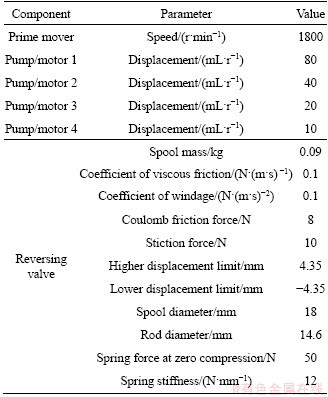
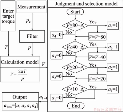
Figure 4 Single-mode digital hydraulic pump/motor variable control flow chart
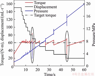
Figure 5 Simulation curve of constant torque control for single-mode system
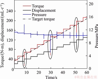
Figure 6 Simulation curve of constant pressure control for single-mode system
In order to compare with the simulation, experiments are carried out on two cases same with simulation, respectively��when pressure rises in the range of 1-20 MPa, target torque maintains constant and when target torque has a linear increase, pressure maintains constant (10.8 MPa). The experimental curves are shown in Figures 8 and 9.
The torque of the secondary components can basically maintain changes around the target torque within the error range, and the displacement changes in a discrete manner while the minimum displacement of the digital hydraulic pump/motor changes in a stepped manner. Through the comparison between Figures 5 and 6 and Figures 8 and 9, it is found that the torque performs well in its tracking characteristics, with several obvious pressure impact points, and the test curve and simulation curve are in high agreement, which proves the accuracy of the simulation model. In the later stage, it can pass the simulation test without the experimental conditions.
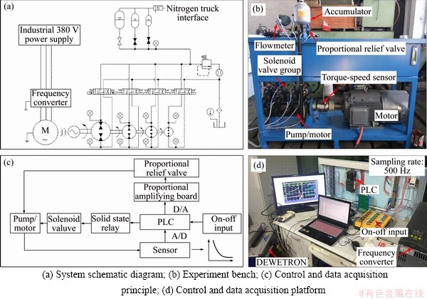
Figure 7 Experimental platform:
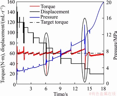
Figure 8 Single-mode constant torque experimental curve
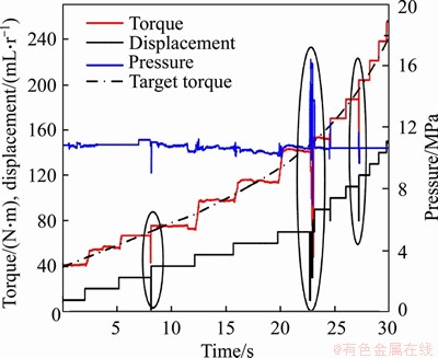
Figure 9 Single-mode constant pressure experimental curve
3 Analysis of dual-mode digital pump/ motor system
3.1 Principle of dual-mode digital pump/motor system
The principle of the n-stage dual-mode digital pump/motor system is shown in Figure 10. Different from single-mode system, the oil discharge and suction ports of the hydraulic pump/ motor are connected with the port P and port T of the electromagnetic reversing valve, respectively. Instead of the direct return to the oil tank, the hydraulic pump/motor is connected to the oil tank through the reversing valve, which enables it to switch between the two modes of pump and motor. When the reversing valve works in the left part, the hydraulic pump/motor is in the pump mode, which absorbs mechanical energy and outputs hydraulic energy. When working in the right part, the hydraulic pump/motor is in the motor mode, which is driven by hydraulic energy to output mechanical energy.
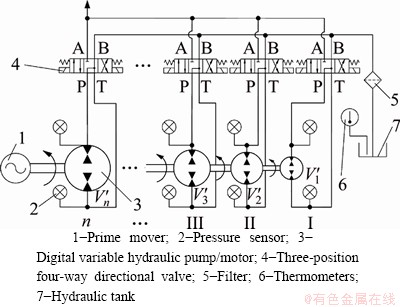
Figure 10 Principle of dual-mode digital hydraulic pump/motor:
To simplify the model in this study, the hydraulic pump/motor is directly driven by the motor. The combined units can work in two modes: pump and motor. Since the whole system always has energy input and the hydraulic energy of the motor mode always comes from the output of the pump mode, the working state of the motor mode cannot be reflected externally. Only when there are energy storage elements in the system can the motor operating conditions become explicit.
Set the displacement of each combined unit as V��i, and when working in dual modes, there are:
 (8)
(8)
where n is the number of combined units; a��i represents the working state of the digital pump/motor in the dual-mode system (when in pump mode, a��i=1; when in unloading mode, a��i=0; when in motor mode, a��i=-1); b��i represents the control-mode coefficient. In the dual mode, to keep the variable fitting resolution unchanged, the control-mode coefficient is taken as b��i=3, and thus the displacement of the combined unit is V��i+1=3V��i, i.e. V��n=V��i3n-1. After the logic control of the switch valve, the effective displacement can be taken within the range of 0 to with the minimum displacement V��1 as the step change, and
  as the variable series.
Assuming the difference between the dual- mode variable series and the single-mode variable series is K, then  which is a monotone increasing function. In the actual system, usually n��2. Obviously, compared with single- mode operation, the displacement variable series of dual-mode operation is expanded, and the difference K increases as the number of combined units increases. When the minimum displacement values are equal, that is V1=V��=V, the displacement variation range under dual-mode operation is
  which is much larger than that of 0-(2n-1)V under single-mode operation. When the minimum displacement values are different, if V1=2V��1=V is taken, the minimum variable step of dual-mode operation is half of that of single-mode operation, with the displacement variation range of dual-mode operation being
  and that of single-mode operation being 0-(2n-1)V. It can be seen that when the combination unit is equal or less than 4, the variable range is similar; when above 4, the variable range of dual mode is much larger than that of single mode, but the fitting accuracy under dual-mode operation is increased by 2 times. For example, to make the displacement ranges of the digital hydraulic pump/motor system as close to each other as possible, the displacement of the single-mode combined units are selected as 10, 20, 40, 80 mL/r, respectively, and that of the dual-mode combined units are 4, 12, 36, 108 mL/r, respectively. After combination, the variable sequence of the two modes is shown in Figure 11.
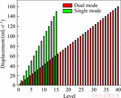
Figure 11 Variable sequences in two modes
Under the single-mode operating characteristic of 4 units, the displacement varies from 0 to 150 mL/r, with the variable series being 16 and the resolution being 10 mL/r. Under the dual-mode operation characteristics, the displacement varies from 0 to 160 mL/r, with the variable series being 40 and the resolution being 4 mL/r. It is consistent with theoretical analysis.
3.2 Mechanism analysis of hydraulic impact
During digital pump/motor variable moments, the flow difference between entering and leaving the dynamic chamber can be approximately considered as equal to the flow difference between digital pump and digital motor, i.e.:
 (9)
(9)
In motor mode, the continuity equation of the flow rate through the motor is:
 (10)
(10)
where Vmi represents the digital pump/motor displacement in motor mode, mL/r; km denotes the leakage coefficient of motor,(L/s)/MPa; pm is the inlet pressure of the motor, MPa; nm represents the motor speed, rad/s.
During the working process of the hydraulic motor, it is necessary to overcome the inertial resistance and viscous resistance inside the components during the movement. The resulting driving torque can be expressed as:
 (11)
(11)
where Tm represents the motor output torque, N��m; ��pD denotes the difference between hydraulic pump/motor inlet and outlet pressure, MPa; Tf denotes any external load torque acting on the shaft of the hydraulic motor, N��m.
The torque equivalent to the shaft end can be expressed as:
 (12)
(12)
For digital hydraulic pump/motor system, the expansion of variable series and the improvement of resolution are particularly important to enhance system dynamic control quality, especially for the system stability and operation smoothness. On the one hand, the complementation of the pressure fluctuation trend (hydraulic diverter) of pump and motor can reduce the peak value of pressure impact. On the other hand, the minimum value can be reduced without changing the number of combination units, both of which are the causes of torque shock.
Due to the factors such as reversing valve response and equivalent function of transition position in the actual system, the actual control effect deviates from the theoretical analysis. Therefore, it is necessary to carry out in-depth simulation or experimental analysis on the control strategy.
3.3 Simulation analysis of dual-mode working state
3.3.1 Control method
According to the principles of digital hydraulic pump/motor displacement control based on dual-mode characteristics, following the change of target torque, taking the system working pressure as the parameter variable, the target displacement of digital hydraulic components is calculated, and the combination closest to the target displacement in the highest resolution range is selected. Taking the combination of 4, 12, 36 and 108 mL/r as an example, the dual-mode digital hydraulic umplmotor variable control block diagram is shown in Figure 12.
3.3.2 Analysis of simulation results
In order to compare the torque shock in single mode and dual mode, the same simulation condition as that of single-mode step variables is designed and simulated. In both cases, the simulation curves based on single-mode and dual-mode are shown in Figure 13.
The simulation results are consistent with theoretical analysis: the torque of the secondary components can basically maintain changes around the target torque within the error range of the two modes, with the displacement changing in a discrete manner and the minimum displacement of the digital hydraulic components in a stepped manner. From the output comparison of constant torques in Figures 13(a) and (c), it can be clearly seen that the combined sequence torque in the single mode has obvious impacts, while in the dual mode the impacts are obviously suppressed. Also, the displacement in the dual mode is more specified than that in the single mode. Besides, from Figures 13(b) and (d), it can also be seen that there are two significant impacts on the torque of the single-mode combined sequence, while in the dual mode the impacts are obviously suppressed. Also, the displacement in the dual mode is more specified than that in the single mode.
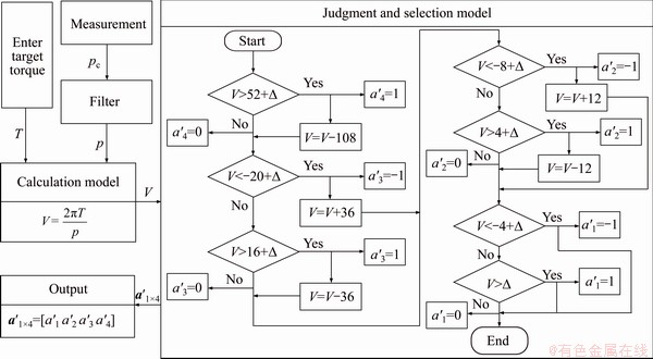
Figure 12 Dual-mode digital hydraulic pump/motor variable control block diagram
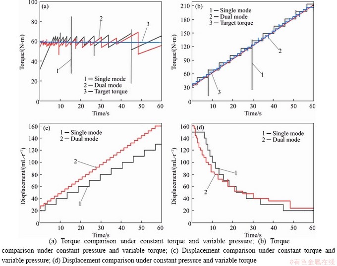
Figure 13 Simulation curves:
In addition to the amplitudes of hydraulic impact, the control quality of digital hydraulic pump/motor is also affected by many factors such as displacement fitting accuracy and pressure impact frequency, so TOPSIS algorithm is introduced for comprehensive evaluation.
4 TOPSIS optimization evaluation method
Multi attribute decision making methods (MADM) are widely used to solve optimization problems [33]. TOPSIS, namely technique for order preference by similarity to ideal solution, is a multi-objective decision-making method applied to comprehensive evaluation problems. In general, based on deterministic methods, the results of MADM used for decision-making can be influenced by several factors [34]. By virtue of MADM, the target sequence can be determined relative to a given standard, thus contributing to the influence of the final decision [35]. The TOPSIS method compares and orthogonalizes the objectives of each scheme before calculating the distance between each objective and the ideal solution [36]. Finally, it calculates the relative proximity of each scheme to the ideal solution.
The TOPSIS algorithm is applied to the comprehensive evaluation and analysis of the operating characteristics of dual-mode and single-mode digital hydraulic pump/motor under constant torque. The steps are as follows:
Firstly, construct a decision matrix X:
 (13)
(13)
where fj (j=1, 2, ��, m) are the target values in each scheme.
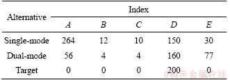
For the comprehensive evaluation of the control characteristics of digital hydraulic pump/ motor, five indexes, including A (the amplitude of torque impact), B (the frequency of torque impact), C (the resolution of displacement), D (the variation range of displacement), and E (the total reversing times of reversing valve in one cycle), are comprehensively considered and analyzed, which are called control quality. It is defined as a torque shock when the torque exceeds ��20% of the target torque. Taking these five evaluation indexes as the target, the approximate operating characteristics of the digital hydraulic pump/motor under constant torque are shown in Table 2. As a comparison, the target value is set to an absolutely ideal situation: the amplitude and frequency of torque impact are 0; the displacement changes completely and continuously, with the variation range being as large as possible, set to [0 200]; the reversing valve does not reverse.
Table 2 Operation characteristics of digital hydraulic pump/motor
So, decision matrix is:
 .
.
Secondly, normalize the decision matrix X: construct a normalized decision matrix X��, in which elements are X��ij and:
 i=1, 2, ��, n; j=1, 2, ��, m (14)
As for the original data index, the lower the four indexes A, B, C and E, the better, which are called low-quality indexes. The higher D, the better, which is called high-quality index. Low-quality indexes need to be converted into high-quality indexes, where the difference method (1-X��ij) should be used.
The normalized decision matrix is:
 .
.
Thirdly, in view of the weight of each target value, a weighted decision matrix Z is constructed, in which the element Zij can be expressed as Zij=WjXij, where i=1, 2, ��, n; j=1, 2, ��, m, and Wj is the weight of the j-th target.
Attributes that play a greater role in the system will be given higher weight. The switching times of the reversing valve determine the service life of the valve group to a certain extent. Frequent reversing will cause the rise of electromagnet temperature, the faults, and even the malfunction of the system. The amplitude A and frequency B of torque impact determine the smoothness of the system and affect its service life. Therefore, according to the importance of each attribute, the weight coefficient values are as follows:
W1=0.3, W2=0.3, W3=0.1, W4=0.1, W5=0.2.
Then the weighted decision matrix Z is:
 .
.
Fourthly, determine the positive and negative ideal solutions. After the conversion, the elements in the decision matrix are all high-quality indexes, so the expressions of positive ideal solution and negative ideal solution can be expressed as follows:
 (15)
(15)
 (16)
(16)
In this paper, the positive and the negative ideal solutions are:
 ;
;
 .
.
Fifthly, calculate the distance  from each scheme to the ideal solution Z+ as well as the distance
  from each scheme to the negative ideal solution Z-, and figure out the relative proximity R of each scheme to the ideal solution.
Use Euclidean Norm as the distance measure, and then:
 (17)
(17)
 (18)
(18)
The relative proximity R of each scheme to the ideal solution is defined as:
 0��Ri��1, i=1, 2, ��, n (19)
Therefore, the relative proximity of the operating characteristics of the digital hydraulic pump/motor to the target value under the constant torque in the two modes is shown in Table 3.
Table 3 Comparison of relative proximity (1)
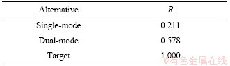
From Table 3, it can be concluded that under constant torque, the control quality of dual-mode digital hydraulic pump/motor is optimized by about 36.7% compared with that of the single mode.
Similarly, under constant pressure and torque rise, the relative proximity of the operating characteristics of the digital hydraulic pump/motor to the target value in the two modes is shown in Table 4.
Table 4 Comparison of relative proximity (2)
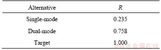
Table 4 shows that under constant pressure and torque rise, the control quality of dual-mode digital hydraulic pump/motor is optimized by about 52.3% compared with that of the single mode.
5 Conclusions
According to the comparison of torque operating characteristics, when ensuring the steady control of the torque, dual mode performs obviously better than single mode in dynamic variable control characteristics. The variable series is expanded from 2n to with the increase of control resolution and the obvious decrease of pressure impact. Besides, the dynamic complementarity of dual mode can greatly reduce the impact and pulsation influence of step variables on the system in single mode. Therefore, it can be seen that the dual-mode operating characteristics of the digital pump/motor can effectively expand the number of variable steps or reduce the displacement steps, thus greatly improving the smoothness and stability of the step variable system.
TOPSIS algorithm has contributed to the comprehensive evaluation of control results of dual-mode displacement control strategy. The results show that the control quality of the digital hydraulic pump/motor after adopting the control strategy has been effectively improved, with an average improvement of about 40%.
There are great differences in the displacement of the combined units required by the dual-mode control methods. It is difficult to realize coaxial series connection in view of the current commercial products. A feasible experimental platform is under development, so this paper only focuses on the simulation and analysis of the theoretical model, while the experimental verification will be carried out in the follow-up research.
In the experimental system, due to long pipelines and complex structures, the response speed of the control signal is affected to a certain extent and the effect on the pressure impact is not clear. In the follow-up research, the flow field parameters after system integration will be analyzed in combination with the structural optimization of digital hydraulic pump/motor.
Contributors
The idea and the overarching research goals were developed by WANG Xin and LIU Xin-hui. WANG Xin and LI Chun-shuang performed the theoretical derivation. WANG Xin, LI Chun-shuang, and QI Hai-bo provided and analyzed the experiment data. LIU Xin-yu provided suggestions and ideas on the control method. The initial draft of the manuscript was written by WANG Xin and LI Chun-shuang. LIU Xin-yu edited the draft of manuscript. All authors replied to reviewers��comments and revised the final version.
Conflict of interest
LI Chun-shuang, WANG Xin, QI Hai-bo, LIU Xin-yu and LIU Xin-hui declare that they have no conflict of interest.
References
[1] WANG Huan-kun, PAUL L. Modelling and energy efficiency analysis of a hybrid pump-controlled asymmetric (single-rod) cylinder drive system [J]. International Journal of Hydromechatronics, 2020, 3(1): 1-25. DOI: 10.1504/ IJHM.2020.105501.
[2] MATTI L. Digital fluid power��state of the art [C]// The 12th Scandinavian International Conference on Fluid Power. Tampere, Finland, 2011: 18-20. https://www.ixueshu.com/ document/6ddee084ae0ffbf2318947a18e7f9386.html.
[3] FLOR M, SCHELLER S, HEIDENFELDER R. Digital hydraulics at Bosch Rexroth��A trend evolves to real applications [C]// The 5th Workshop on Digital Fluid Power. Tampere, Finland, 2012: 5-14. https://trepo.tuni.fi/ bitstream/handle/10024/116752/DFP12_proceedings.pdf?sequence=1&isAllowed=y#page=8.
[4] AHSAN S, S MEHDI R, MOHAMMAD Z. Energy-efficient position control of an actuator in a digital hydraulic system using on/off valve [C]// 2016 4th International Conference on Robotics and Mechatronics (ICROM). Tehran, Iran, 2008: 34-45. DOI: 10.1109/ICRoM.2016. 7886852.
[5] GAN Zhen-yu, KATELYN F, R BRENT G. A novel variable transmission with digital hydraulics [C]// 2015 IEEE/RSJ International Conference on Intelligent Robots and Systems (IROS). Hamburg, Germany, 2015: 5838-5843. DOI: 10.1109/IROS.2015.7354206.
[6] SHEN Wei, MAI Yun-fei, SU Xiao-yu, ZHAO Jin-bao, JIANG Ji-hai. A new electric hydraulic actuator adopted the variable displacement pump [J]. Asian Journal of Control, 2016, 18(1): 178-191. DOI:10.1002/asjc.1200.
[7] EHSAN M, RAMPEN W H S, SALTER S H. Modelling of digital-displacement pump-motors and their application as hydraulic drives for nonuniform loads [J]. Journal of Dynamic Systems Measurement and Control, 2000, 122(1): 210-215. DOI: 10.1115/1.482444.
[8] SONG Fei, LOU Jing-jun, PENG LI-kun. Energy-saving improvement and simulation study on digital hydraulic system [C]// 2015 International Conference on Advanced Mechatronic Systems (ICAMechS). Beijing, China: IEEE Conference Publications, 2015: 310-315. DOI: 10.1109/ ICAMechS.2015.7287080.
[9] LIU Cheng-qiang, LIU Yin-shui, LIU Jia-xin. Electro- hydraulic servo plate-Inclined plunger hydraulic transformer [J]. IEEE Access, 2016, 4: 8608-8616. DOI: 10.1109/ ACCESS.2016.2628355.
[10] WANG Li, LIU Xin-hui, WANG Xin, CHEN Jin-shi, LIANG Yi-jie. Strategy of digital hydraulic transmission system for loaders [J]. Journal of Jilin University (Engineering Science), 2017, 47(3): 819-826. DOI: 10.13229/j.cnki.jdxbgxb201703018. (in Chinese)
[11] MIKKO H, MATTI L. Displacement control of a mobile crane using a digital hydraulic power management system [J]. Mechatronics, 2013, 23(4): 452-461. DOI: 10.1016/ j.mechatronics.2013.03.009.
[12] GONG Jun, ZHANG Da-qing, GUO Yong. Power control strategy and performance evaluation of a novel electro- hydraulic energy-saving system [J]. Applied Energy, 2019, 233-234: 724-734. DOI: 10.1016/j.apenergy.2018.10.066.
[13] HELMUT K, RUDOLF S, MICHAEL E, EMANUELE G. A compact hydraulic switching converter for robotic applications [C]// Fluid Power and Motion Control (FPMC 2010). Bath, UK, 2010: 55-68. https://xueshu.baidu.com/ usercenter/paper/show?paperid=718ed324b469c08ee21b190f842fc7bd&site=xueshu_se.
[14] VICTOR J, WANG Peng-fei, ANDREW P, JOHNSTON D N. Behavioral prediction of hydraulic step-up switching converters [J]. International Journal of Fluid Power, 2014, 15(1): 1-9. DOI:10.1080/14399776.2014.882057.
[15] RAINER H, EVGENY L, RUDOLF S. An RC filter for hydraulic switching control with a transmission line between valves and actuator [J]. International Journal of Fluid Power, 2014, 15(3): 139-151. DOI:10.1080/14399776.2014.970974.
[16] MOORHEAD J R. Saving energy with ��digital�� pump system [J]. Machine Design, 1984, 56(4): 40-44. https:// www.researchgate.net/search.Search.html?type=researcher&query=.
[17] ZHANG Li-ping, ZHOU Lan-wu, LIU Fen. Study on energy saving method of fixed displacement pump hydraulic system [J]. Chinese Mechanical Engineering, 2011, 12(1): 36-38. DOI: 10.3321/j.issn:1004-132X.2001.z1.014. (in Chinese)
[18] LIU Xin-hui, WANG Tong-jian. Step variable system with multi gear pumps: China, 201110107578.3 [P]. 2011. (in Chinese)
[19] ROEMER D, BECH M, JOHANSEN P, PEDERSEN H. Optimum design of a moving coil actuator for fast-switching valves in digital hydraulic pumps and motors [J]. IEEE/ASME Transactions on Mechatronics, 2015, 20(6): 2761-2770. DOI: 10.1109/TMECH.2015.2410994.
[20] HEITZIG S, THEISSEN H. Aspects of digital pumps in closed circuit [C]// The 4th Workshop on Digital Fluid Power. Linz, Austria, 2011. https://www.tandfonline.com/doi/abs/ 10.1080/14399776.2012.10781060.
[21] HEITZIG S, SGRO S, THEISSEN H. Energy efficiency of hydraulic systems with shared digital pumps [J]. International Journal of Fluid Power, 2012, 13(3): 49-57.
[22] MIIKKA K, MATTI L. Digital hydraulic IMV system in an excavator�Cfirst results [C]// The Sixteenth Scandinavian International Conference on Fluid Power. Tampere, Finland, 2019. https://www.researchgate.net/publication/336209686.
[23] LAAMANEN A, LINJAMA M, VILENIUS M. On the pressure peak minimization in digital hydraulics [C]// The Tenth Scandinavian International Conference on Fluid Power. Tampere, Finland, 2007. http://URN.fi/URN:NBN:fi:tty- 201403281139.
[24] LAAMANEN A, ANTTONEN P, LINJAMA M. Digital low control unit for controlling amount of water used for binding dust [C]// The Third Workshop on Digital Fluid Power. Tampere, Finland, 2010. http://URN.fi/URN:NBN:fi:tty- 201404081142.
[25] HEIKKILA M, LINJAMA M. Improving damping characteristics of displacement controlled digital hydraulic system [C]// The Fifth Workshop on Digital Fluid Power, Tampere. Finland, 2012. https://trepo.tuni.fi/bitstream/ handle/10024/116752/DFP12_proceedings.pdf?sequence=1#page=78.
[26] WANG Jia-yi, LIU Xin-hui, WANG Xin, QI Hai-bo, SUN Xiao-yu, WANG Li. Mechanism and inhibition for displacement shifting impact on digital secondary component [J]. Journal of Jilin University (Engineering Science), 2017, 47(6): 1775-1781. DOI: 10.13229/j.cnki.jdxbgxb201706014. (in Chinese)
[27] YAO Jing, ZHANG Yang, CHEN Hao, KONG Xiang-dong. Flow characteristics of (D+A) combination controlled multi-pump hydraulic system [J]. Chinese Hydraulics & Pneumatics, 2017(8): 79-83. DOI: 10.11832/j.issn.1000- 4858.2017.08.014. (in Chinese)
[28] ZHANG Yang. Control characteristics of D+A combined multi-pump controlled system [D]. Qinhuangdao: Yanshan University, College of Mechanical Engineering, 2017. https://xueshu.baidu.com/usercenter/paper/show?paper id=1s1k0pp0md3w0gv0e22b0j70m2114745&site=xueshu_se.(inChinese)
[29] LIU Tao, SUN Hui, JIANG Ji-hai. Investigation to simulation of control strategy of parallel hydraulic hybrid vehicles based on backward modeling [C]// 2009 International Conference on Mechatronics and Automation. Changchun, China: IEEE Conference Publications, 2009: 551-556. DOI: 10.1109/ICMA.2009.5246640.
[30] LIU Xin-hui, WANG Wei, LIU Xiao-feng. Research for energy management mode of parallel hydraulic hybrid vehicle [C]// Proceedings of 2011 International Conference on Electronic & Mechanical Engineering and Information Technology. IEEE Conference Publications, 2011: 3824-3827. DOI. 10.1109/ICMA.2009.5246640.
[31] LUMKES J H, FRONCZAK F J. Design simulation and validation of a bond graph model and controller to switch between pump and motor operation using four on/off valves with a hydraulic axial piston pump/motor [C]// Proceedings of the 2000 American Control Conference. ACC (IEEE Cat. No.00CH36334). IEEE Conference Publications, 2000: 3605-3609. DOI: 10.1109/ACC.2000.879242.
[32] WANG Ji-sen, WANG Hai-tao, LI Shi-hui. The parameter analysis and simulation of accumulator in hydraulic test bench [J]. Machine Tools & Hydraulics, 2010, 38(15): 89-91. DOI: 10. 3969/j.issn.1001-3881.2010.15.028. (in Chinese)
[33] KHALKHALI A, SHOJAEEFARD M H, DAHMARDEH M, SOTOUDEH H. Optimal design and applicability of electric power steering system for automotive platform [J]. Journal of Central South University, 2019, 26(4): 839-851. DOI: 10.1007/s11771-019-4053-3.
[34] LIU P. Multi-attribute decision-making method research based on interval vague set and TOPSIS method [J]. Ukio Technologinis Ir Ekonominis Vystymas, 2009, 15(3): 453-463. DOI: 10.3846/1392-8619.2009.15.453-463.
[35] ASHRAF Q M, HABAEBI M H, ISLAM M R. TOPSIS- Based service arbitration for autonomic Internet of things [J]. IEEE Access, 2016, 4: 1313-1320. DOI: 10.1109/ACCESS. 2016.2545741.
[36] XIA Yi-min, LIN Lai-kuang, WU Dan, JIA Lian-hui, CHEN Zhuo, BIAN Zhang-kuo. Geological adaptability matching design of disc cutter using multicriteria decision making approaches [J]. Journal of Central South University, 2018, 25(4): 843-854. DOI: 10.1007/s11771-018-3788-6.
(Edited by ZHENG Yu-tong)
���ĵ���
����˫ģʽ���Ƶ����ֱ�/����ѹ�������Ż��о�
ժҪ������ʽҺѹ��/������гɱ��͡���Ӧ�졢����Ⱦ���ŵ㣬�ںܶ�Ӧ��������Դ��泣��ı�����/���Ȼ��������ҺѹԪ���ڱ���˲������ϴ��Һѹ����������̻�еԪ����ʹ��������ͨ�������ֱ�/����ı������̽��з���������֣��������ݱ仯���µ������������Dz���Һѹ����ĸ���ԭ����ʵ����Ե����ݷ�������������������Ǻ϶Ƚϸߡ����Һѹ����Ԫ�����ص㣬����˻���˫ģʽ�������Եı������Ʒ���������TOPSIS�㷨�Բ��ø÷�������������ƽ�������ۺ����ۣ�������������ø���Ϸ���������ֱ�/����Ŀ���Ʒ�ʵõ�����Ч����ߣ�ƽ�����Լ40%��
�ؼ��ʣ�����Һѹ��˫ģʽ�������ԣ�AMESim���棻TOPSIS�㷨
Foundation item: Project(51405183) supported by the National Natural Science Foundation of China
Received date: 2019-08-06; Accepted date: 2020-06-26
Corresponding author: WANG Xin, PhD, Associate Professor; Tel:+86-13756556339; E-mail: wangxin_jlu@jlu.edu.cn; ORCID: https:// orcid.org/0000-0003-1211-7292; LIU Xin-hui, PhD, Professor; Tel: +86-13904339605; E-mail: liuxh@jlu.edu.cn; ORCID: https://orcid.org/0000-0001-8946-9427

