Layout design for disc cutters based on analysis of TBM cutter-head structure
��Դ�ڿ������ϴ�ѧѧ��(Ӣ�İ�)2018���4��
�������ߣ������� ����� GUO Wei(��ΰ) ������ ��С��
����ҳ�룺812 - 830
Key words��split type cutter-head; disc cutters�� layout; genetic algorithm; equal life; equal wear; star layout pattern
Abstract: Studies to date have failed to consider gage disc cutters�� variable cutting depth and the constraints of cutter-head welds, and have ignored the coupling mechanism between the profile of the full-face rock tunnel-boring machine (TBM) cutter-head and the assembled radius layout of the disc cutters. To solve these problems, an adaptive design method for studying cutter layout was proposed. Taking the bearing stress of the outermost gage disc cutter as an index, the profile of the cutter-head was determined. Using a genetic algorithm and based on the principles of equal life and equal wear, the assembled radii of the cutters were optimally designed. Boundary conditions of non-interference between the cutters, manholes, muck buckets and welding lines were given when a star layout pattern was used on cutters. The cutter-head comprehensive evaluation model was established by adopting relative optimization improvement degree of evaluation indices to achieve dimensional consistency. Exemplifying the MB264-311-8030 mm tape TBM cutter-head, the calculations show that compared with the original layout scheme, among the 51 disc cutters, the largest gap of the cutters�� assembled radiuses is only 25.8 mm, which is 0.64% of the cutter-head��s radius and is negligible. The cutter-head��s unbalanced radial force decreases by 62.41%, the overturning moment decreases by 33.22%, and the cutter group��s centroid shift increases by only 18.48%. Each index is better than or approximately equal to the original cutter-head layout scheme, and the equivalent stress and deformation are both smaller; these results fully verify the feasibility and effectiveness of the method.
Cite this article as: SUN Hong-yan, GUO Wei, LIU Jian-qin, SONG Li-wei, LIU Xiao-qing. Layout design for disc cutters based on analysis of tbm cutter-head structure [J]. Journal of Central South University, 2018, 25(4): 812�C830. DOI: https://doi.org/10.1007/s11771-018-3786-8.

J. Cent. South Univ. (2018) 25: 812-830
DOI: https://doi.org/10.1007/s11771-018-3786-8

SUN Hong-yan(�����), GUO Wei(��ΰ), LIU Jian-qin(������),SONG Li-wei(������), LIU Xiao-qing(��С��)
School of Mechanical Engineering, Tianjin University, Tianjin 300072, China
 Central South University Press and Springer-Verlag GmbH Germany, part of Springer Nature 2018
Abstract: Studies to date have failed to consider gage disc cutters�� variable cutting depth and the constraints of cutter-head welds, and have ignored the coupling mechanism between the profile of the full-face rock tunnel-boring machine (TBM) cutter-head and the assembled radius layout of the disc cutters. To solve these problems, an adaptive design method for studying cutter layout was proposed. Taking the bearing stress of the outermost gage disc cutter as an index, the profile of the cutter-head was determined. Using a genetic algorithm and based on the principles of equal life and equal wear, the assembled radii of the cutters were optimally designed. Boundary conditions of non-interference between the cutters, manholes, muck buckets and welding lines were given when a star layout pattern was used on cutters. The cutter-head comprehensive evaluation model was established by adopting relative optimization improvement degree of evaluation indices to achieve dimensional consistency. Exemplifying the MB264-311-8030 mm tape TBM cutter-head, the calculations show that compared with the original layout scheme, among the 51 disc cutters, the largest gap of the cutters�� assembled radiuses is only 25.8 mm, which is 0.64% of the cutter-head��s radius and is negligible. The cutter-head��s unbalanced radial force decreases by 62.41%, the overturning moment decreases by 33.22%, and the cutter group��s centroid shift increases by only 18.48%. Each index is better than or approximately equal to the original cutter-head layout scheme, and the equivalent stress and deformation are both smaller; these results fully verify the feasibility and effectiveness of the method.
Key words: split type cutter-head; disc cutters�� layout; genetic algorithm; equal life; equal wear; star layout pattern
Cite this article as: SUN Hong-yan, GUO Wei, LIU Jian-qin, SONG Li-wei, LIU Xiao-qing. Layout design for disc cutters based on analysis of tbm cutter-head structure [J]. Journal of Central South University, 2018, 25(4): 812�C830. DOI: https://doi.org/10.1007/s11771-018-3786-8.
1 Introduction
The full face rock tunnel boring machine, abbreviated TBM, is the flagship product of China��s large-scale equipment manufacture sector. The cutter-head, located at the front of a TBM, directly contacts the tunnel face and is the key factor in whether it is efficient, reliable and stable during excavation [1, 2]. TBM cutter-head design primarily involves the structure design of disk body and the layout design of cutter group. Many researchers have studied cutters�� layout pattern, layout optimization methods and coupling arrangements between the cutters and the cutter- head structure [3�C6].
The layout design of the disc cutters includes the design of the cutters�� spacing (in a radial direction) and their arrangement on the cutter-head (in a circumferential direction). Although some results have been achieved in the study of disc cutters��layout, many aspects can be improved. For instance, taking V-shaped cutters as the research object, this does not correspond with the present practical approximate constant cross section cutters; for gage disc cutters, the characteristics of variable cutting depth have not been considered. Most of the cutter-heads used in TBM have a plane layout. The size of the cutter-head is decided by the diameter of the tunnel, according to where the cutters are installed, and the profile of the cutter-head is divided into three zones: the center cutter zone, the normal cutter zone and the gage cutter zone. Among these zones, determining the transitional arc area is complicated, and it is the key issue in determining the cutter-head profile shape. At present, in radial layout design, researches on defining different regions of the cutter-head and designing the obliquity range for the transitional arc area are very scarce. Nonetheless, size determination of different regions of the cutter-head is prerequisite for practical cutter-head design and layout. Moreover, the major diameter cutter-heads usually adopt block design structure for easy transport. All blocks are welded together after being connected via bolts on site. Because the stiffness and strength of the cutter-head are low at weld sites, cutters cannot be arranged in these places. At present, the influence of cutter-head welds is not considered in the circumferential layout design of cutters, so there is still a long way to go in this field.
According to the technical engineering requirements and corresponding cutter-head structural design requirements, a medium square five-section cutter-head was taken as a case; the radial and circumferential model of the cutter layout were established. GUO et al [7] has established the radial model. In the radial layout design of cutters, First, to leave the center cutters and normal cutters�� installed area unchanged in the TBM cutter-head��s original design scheme, a new method of determining the installed obliquity range for the gage cutters was proposed by taking the bearing stress of the outermost gage disc cutter as an evaluation index. Then the profile was determined according to the relationship between the size of the cutter-head��s transition zone, the fillet radius and the installed tilt angle. Next, the formulas for the rock-breaking amount for cutters with a constant cross section and for calculating wear extent for gage cutters were derived. On this basis, using a genetic algorithm, based on the principle of equal life, the assembled radiuses of the center cutters and normal cutters were optimally designed; based on the principle of equal wear, establishing a nonlinear mathematics model, the tilt angles of the gage cutters were also optimally designed. Based on these results, the circumferential model was established continuously for the circumferential layout design of cutters. The boundary conditions of non-interference between cutters, manholes, muck buckets and welding lines in the radial and circumferential direction were given when star layout pattern was used on cutters. Based on this, a comprehensive cutter-head evaluation model was established by taking the cutter-head��s unbalanced radial force, overturning moment and the cutter group��s centroid shift as evaluation indices. A new method for cutter layout was proposed accordingly. Finally, exemplifying the MB264-311-8030 mm type TBM cutter-head in the draw water tunnel project of Liaoning Dahuofang Reservoir, the feasibility and effectiveness of the model were verified by designing its transitional arc area and arranging its cutters in the radial and circumferential directions.
2 Coupling layout design between TBM cutter group and cutter-head structure
The medium square five-section type of cutter-head was taken as a research object and the star layout pattern was adopted. Based on the principles of equal life and equal wear, related models were established; optimum designs of polar radii for the center cutters and normal cutters and tilt angles for the gage cutters were created; and an adaptive design method based on the profile of the cutter-head was proposed. The boundary conditions of non-interference between the cutters, manholes, muck buckets and welding lines in the radial and circumferential directions were given, and the cutter-head comprehensive evaluation model was established, putting forward a new method for cutter layout. The overall technical route of research is shown in Figure 1.
3 Adaptive design of cutter-head profile
3.1 Stress characteristic analysis of cutter bearing
Bearings used in disc cutters for the TBM cutter-head are usually Timken single-row taper roller bearings; the structural diagram of the bearings installed in the gage cutters is shown in Figure 2(a). To determine the installed tilt angle range for the gage cutters, the bearing stress of the outermost gage disc cutter was chosen as the evaluation index. A pair of tapered roller bearings installed on the gage cutter share responsibility for radial and axial forces in the cutting process. The loads of the bearings were analyzed with reference to the research of SHEN [8]. The simplified force diagram is shown in Figure 2(b); the calculation formulas are shown in Eqs. (1) and (2).
 (1)
(1)
 (2)
(2)
where Frj is the radial force of the jth bearing, Faj is the axial force of the jth bearing, Pj is the equivalent dynamic load of the jth bearing; fpj is the loading coefficient of the jth bearing; Xj is the radial dynamic load coefficient of the jth bearing; Yj is the axial dynamic load coefficient of the jth bearing (j=1, 2); l is the distance between the two bearings; y is the derived axial force coefficient; and d is the diameter of the cutter. FN is the normal force of the cutter and FR is the rolling force of the cutter, both calculated by the CSM model [9]. FS is the side force of the cutter, considering the variable cutting depths of the gage cutters, and on the basis of Ref. [10], its side forces can be formulated as
 (3)
(3)

where f is the contact angle between the disc cutter and the rock; �� is the shear strength of the rock; ��i is the assembled radius of the ith cutter, ��i is the tilt angle of the ith cutter, and h��is the penetration depth of the ith cutter.

Figure 1 Overall technical roadmap of study

Figure 2 Structure of bearings installed in gage cutters and a simplified force sketch:
3.2 Determination of installed tilt angle range for cutters
The profile of the cutter-head is divided into three zones according to the cutters��different installed locations: the center cutter zone, the normal cutter zone and the gage cutter zone. The specific arrangement is shown in Figure 3, where Rf is the area range occupied by the center cutters and the normal cutters.
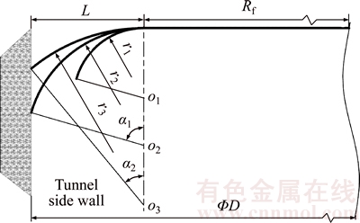
Figure 3 Profile of cutter-head
Figure 3 illustrates that the transition arc region is the key factor in determining the TBM cutter-head profile; the larger the fillet radius is, the gentler the transition area and the smaller the total tilt angle. The relationship between the cutter- head��s transition zone size, the fillet radius and the installed tilt angle can be formulated as
r=L/sin�� (4)
where L is the size of the transition zone, r is the fillet radius, and �� is the installed tilt angle range.
4 Optimal designs of assembled radii of center cutters and normal cutters based on equal life principle
4.1 Calculation of broken rock for normal cutters
Among all cutters on the TBM cutter-head, the normal cutters are the main ones that break rock. They are installed in concentric circles centered on the cutter-head center; when the tunnels are excavated, the farther away the cutter is from the cutter-head center, the longer the path of the cutting rock and the more serious the cutter ring��s wear. Researches show that wear is proportional to the rock-breaking amount [11, 12]. To quantitatively describe wear differences between cutters, the rock-breaking amount is used to make calculations. To reduce differences in the rock-breaking amount, the cutters�� assembled radii should be unequally spaced: the farther away the cutter is from the cutter-head center, the smaller the cutter spacing. During driving, to ensure there is no rock ridge between the cutters, the breaking rock volume of adjacent cutters should be intersecting.
Assume that the position numbers of three adjacent cutters are i�C1, i and i+1 respectively; the cutter spaces are Si and Si+1. The breaking rock area of the ith cutter is the shaded part in Figure 4.

Figure 4 Diagram of breaking rock volume for adjacent cutters
As shown in Figure 4, assume that there are n center cutters and m normal cutters; the ith normal cutter��s breaking rock area can be formulated as
 (5)
(5)
where i=1, 2, ��, m�C1, Si is cutter spacing between the ith cutter and the (i�C1)th cutter, �� is half broken angle of the rock.
Assume that the bilateral cutter spaces of the last normal cutter are equal, then
 (6)
(6)
Therefore, when the cutter-head rotates one cycle, the breaking rock volume of the ith cutter driven by the cutter-head can be formulated as
 (7)
(7)
where ��1 is the assembled radius of the last center cutter.
Assume that the center cutters�� cutter spacing is u, and the offset distance of the first center cutter is u1, then
 (8)
(8)
4.2 Optimization of polar radiuses for center cutters and normal cutters
The offset distance of the first center cutter, the cutter space of the other center cutters and the cutter spaces of the normal cutters were taken as design variables; the minimum variance of the normal cutters�� breaking rock volume was taken as the optimization objective. Using a genetic algorithm to optimize the design, mathematical model 1 can be formulated as
 (9)
(9)


 (10)
(10)
5 Optimal designs of tilt angles of gage cutters based on equal wear principle
5.1 Calculation of wear loss for gage cutters
In the process of actual hard rock excavation, the cutter ring��s wear is the main cause of failure for the gage cutters. ZHANG et al [13] has studied the formula for the arc length of the gage cutter��s rock breakage point during a cutting depth process; SHU [14] has studied the wear volume calculation for the disc cutters based on abrasive wear. Making use of these two formulas, the formula of the wear volume for each gage cutter can be obtained after the cutter-head rotating one cycle.
1) Calculation formula of the wear volume Wp after one rotation was established based on a plastic removal mechanism
The wear volume of the front point of the disc cutter in the contact region after one rotation can be formulated as

 (11)
(11)
where s is the arc length taken by the rock breakage point of the gage cutter during a cutting depth process; ��i is the assembled radius of the ith gage cutter, ��i=Rf +r��sin��i;  is the wear rate of this point; K is the abrasive wear coefficient; H is the material hardness of the cutter ring; and p0 is the base contact stress.
The wear volume of the front of the disc cutter ring after one rotation can be formulated as
 (12)
(12)
2) Calculation formula of the wear volume Wq after one rotation was established based on toughness removal mechanism
The wear volume of the front point of the disc cutter in the contact region after one rotation can be formulated as


 (13)
(13)
where  is the wear rate of this point; K1 denotes the abrasive shape and the distribution coefficient; d'is the average diameter of the abrasion; and Kc is the fracture toughness of the material.
The wear volume of the front of the disc cutter ring after one rotation can be formulated as
 (14)
(14)
Coupling these two material removal mechanisms, the wear volume of the front of the disc cutter ring after one rotation can be formulated as [14]
 (15)
(15)
where a=0.857; b=0.167.
The wear volume of each gage cutter after the cutter-head rotating one cycle can be formulated as
 (16)
(16)
5.2 Optimization of tilt angles for gage cutters
The tilt angle differences between adjacent gage cutters were taken as design variables; the minimum variance of the gage cutters�� wear volume was taken as the optimization objective, using a genetic algorithm to optimize design. Assuming that there are z gage cutters, the nonlinear mathematical model 2 can be formulated as
 (17)
(17)


 (18)
(18)
where
 (19)
(19)
6 Solution of boundary conditions
Locations of the cutters on the cutter-head are represented in the form of polar coordinates. Cutters thus have two degrees of freedom��the assembled radius �� and the polar angle ��. At present, there are three layout patterns: multi-spiral, star and stochastic,as shown in Figure 5 [15]. The degrees of freedom and parameters of these three layout patterns are shown in Table 1.No matter which layout pattern is adopted, once these two parameters are determined, the layout of the cutters is fixed.
At the same time, the major diameter cutter-heads usually adopt block design structure for easy manufacture and convenient transportation to the construction site. At present, there are four main types of subdivided cutter-head structure, as shown in Figure 6. The layout of split type cutter-heads has more restrictions because of the existence of welds.

Figure 5 Different layout patterns of disc cutters [15]:
Table 1 Number of degrees of freedom and parameters of different layout patterns

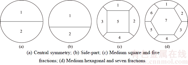
Figure 6 Subdivision forms of cutter-head structure:
The medium square five-section cutter-head was taken as a research object and the star layout pattern was adopted; Figures 5(b) and 6(c) show that when the cutters are arranged on the cutter- head in a circumferential direction, they are restricted by many constraints. According to the different constraint directions, they can be divided into two categories: radial and circumferential constraints. With radial constraint, cutters must not interfere with horizontal and vertical welds; the circumferential constraint requires there to be no interference between cutters, and the cutters cannot interfere with the muck buckets, manholes and 45��welds.
6.1 Non-interference criterion in radial direction
Set each group with four star lines, with the groups uniformly distributed around the cutter-head center; the tilt angle of the star line in the first quadrant was defined as the tilt angle of the group, as shown in Figure 7. Because star line groups and the cutter-head welds are both centrally symmetrical, it is only necessary to give the boundary conditions of non-interference between the cutters and welding seams in the first quadrant.
Assume that D is the diameter of the cutter-head, ��T is the side length of the central block, and ��L is the length and ��W is the width of the cutter holes. Figure 7 shows that the boundary condition consists of two parts, the center block area and the edge block area.
For the center block area, set ��x1 as the tilt angle of the star line, and set ��x1 as the critical interference polar radius between the cutter hole and the weld on the star line, then:
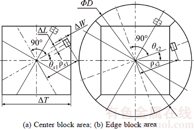
Figure 7 Critical interference between cutters and welds in radial direction:
 (20)
(20)
For the edge block area, set ��x2 as the tilt angle of the star line, and set ��x2 as the critical interference polar radius between the cutter hole and the weld on the star line, then:
 (21)
(21)
The non-interference criterion between the cutters and welds can be summarized as follows: for the center block area, when the cutter��s assembled radius ��<��x1, it can be arranged on a star line group with the tilt angle ��x1; for the edge block area, when the cutter��s assembled radius ��>��x2, it can be arranged on a star line group with the tilt angle ��x2.
6.2 Non-interference criterion in circumferential direction
There are two possible design methods involving non-interference between the cutters, muck buckets, manholes and 45�� welds: in the first, the locations of the muck buckets, manholes and 45�� welds are known, and the locations of the star line groups are determined by avoiding these areas; in the second, the star line groups are fixed and the other three features are determined accordingly. This paper adopts the first design method, namely studying the non-interference criterion between the cutters without changing the locations of the muck buckets, manholes and 45�� welds of the MB264-311-8030 mm tape TBM cutter-head.
For the center block area, the nearer the cutters are to the cutter-head center, the more limited the area of the cutter layout and the greater the chance of interference between the cutters. There are four manholes on the cutter-head and they are uniformly distributed around the cutter-head center. The location parameter ��r of the manhole in the first quadrant meets the condition 45��<��r<90��. Considering the location of the manhole, the tilt angle of the star line group ��x1 should meet the condition 0��ܦ�x1��45��, as shown in Figure 8. Thus, for the star line group with the tilt angle ��x1, the critical interference polar radius �ѡ�x between the cutters can be formulated as
 (22)
(22)
For the edge block area, there are eight muck buckets on the cutter-head, which are uniformly distributed around the cutter-head center; long and short muck buckets are arranged alternately. There are two kinds of muck bucket: ��c1 is the tilt angle of the No. 1 muck bucket; its length is denoted by ��L�� and its width is denoted by ��W��; ��c2 is the tilt angle of the No. 2 muck bucket; its length is denoted by ��L�� and its width is denoted by ��W��; ��W��=��W��. Assume that ��x2 meets the condition 0�㣼��x2��45��; when interference occurs between the cutters, the critical tilt angle of the star line group is ��x1��; when interference occurs between the cutters and the No. 1 muck bucket, the critical tilt angle of the star line group is ��x1��, as shown in Figure 9. Assume that ��x2 meets the condition 45��<��x2��90��, when interference occurs between the cutters and the 45�� welds, the critical tilt angle of the star line group is ��x2��; when interference occurs between the cutters and the No. 2 muck bucket, the critical tilt angle of the star line group is ��x2��, as shown in Figure 10. Then:
 (23)
(23)
 (24)
(24)

Figure 8 Critical interference between cutters in circumferential direction for center block area

Figure 9 Critical interference in circumferential direction for edge block area within range 0��C45��
The non-interference criterion in the circumferential direction can be summarized as follows: for the center block area, the tilt angle of the star line group ��x1 should meet the condition 0��ܦ�x1��45��, and when the cutter��s assembled radius ��x>�ѡ�x, it can be arranged on a star line group with the tilt angle ��x1; for the edge block area, when ��x2 is within the range 0��C45��, ��x2 should meet the condition ��x1'<��x2<��x1��; when ��x2 is within the range 45��C90��, ��x2 should meet the condition ��x1��<��x2 <��x2��.

Figure 10 Critical interference in circumferential direction for edge block area within the range 45��C90��
7 Comprehensive evaluation model of TBM cutter-head
7.1 Forces acting on disc cutter
As shown in Figure 11, the cutting forces on a disc cutter mainly involve the normal force FN, the rolling force FR and the side force FS. Figure 11 illustrates these three forces exerted on the tip of the disc cutter during excavation; in addition, the inertial forces caused by the movement of a disc cutter include the relative motion inertial force, the Coriolis inertial force FG and the Convected inertial force Fe. Among these three, the relative motion inertia force is self-balanced.
The Coriolis inertial force FG affects the force balance of the TBM cutter-head in the form of a couple. The ith cutter��s moment of couple can be formulated as
 (25)
(25)
where m is the mass of the cutter, �� is the rotational speed of the cutter-head, r is the radius of the cutter, and ��i is the assembled radiuses of the ith cutter.
The Convected inertial forces converge at the gyration center of the cutter-head along the normal direction of the cutters�� locus circles, and constitute a system of plane intercrossing forces. The ith cutter��s Convected inertial force Fei can be formulated as
 (26)
(26)
7.2 Evaluation indices of cutter layout
When the constraint conditions for non-interference between the cutters, muck buckets, manholes and welds are satisfied, the cutter-head has three comprehensive evaluation indices, namely the unbalanced radial force, the overturning moment of the cutter-head and the centroid shift of the cutter group, and these three indicators should be as small as possible. Set the cutter-head to anticlockwise rotation and according to Figure 11, then the calculation formulas of these three indicators can be formulated as follows.

Figure 11 Individual forces acting on a normal cutter and a gage cutter [16]
The unbalanced radial force of the cutter-head
 (27)
(27)
where for the center cutters and the normal cutters,


For the edge cutters,


where Fx is the component in the x direction of the unbalanced radial force, Fy is the component in the y direction of the unbalanced radial force, FNi is the normal force of the ith cutter, FRi is the rolling force of the ith cutter, Fbi is the radial component of the ith cutter force, Fei is the Convected inertial force of the ith cutter, FSi is the side force of the ith cutter, ��i is the polar angle of the ith cutter.
The overturning moment of the cutter-head
 (28)
(28)
where
 Mx is the component in the x direction of the overturning moment, and My is the component in the y direction of the overturning moment.
The centroid shift of the cutter group
 (29)
(29)
where ym=
ym=
where (xm, ym) is the centroid position of all cutters; (xi, yi) is the centroid position of the ith cutter; mi is the mass of the ith cutter, mi=m; and Q is the number of cutters.
To quantitatively analyze the multi-objective problem, a linear weighting method is adopted to construct the synthetic evaluation function EV of the cutter-head. The corresponding weights of three indices (C1, C2 and C3) are a1, a2 and a3, respectively, and the EV can be formulated as
 (30)
(30)
Because the dimension of these three indices is not unified, the improvement degree of their relative optimization was adopted to achieve dimensional consistency. Assume that sumF1, sumM1 and sumL1 are the unbalanced radial force, overturning moment and centroid shift of the initial cutter arrangement, respectively; then for the kth (k��2) cutter arrangement, the dimensional consistency of each index can be expressed as the ratio between the cumulative calculation result for each index in the (k�C1)th cutter arrangement and the difference value of the cumulative calculation result for each index in the kth and (k�C1)th cutter arrangement.
 (31)
(31)
GENG [17] pointed out that the main consideration in the project is minimizing the overturning moment; this is followed by the unbalanced radial force, and lastly the centroid shift of the cutter group, so that C2>C1>C3 in importance.
According to AHP, the judgment matrix A should be formulated as

The greatest eigenvalue �� and the greatest eigenvector W can be formulated as


The concordance index CI=0.009, the random consistency index RI=0.58 (lookup table), and the consistency ratio CR=0.016<0.1 pass the consistency check.
The characteristic vector W can thus be used as a weight vector; the synthetic evaluation function in the kth cutter arrangement can be formulated as

 (32)
(32)
7.3 Method for determining circumferential layout of cutters
The number of cutters and the tilt angles of the star line groups are known; set every V (V can be 1, 2 or 4) cutters as a group. When determining the layout for each group of cutters, according to the critical interference polar radii determining an optimal star line group and arranging the cutters on it along the reverse of the cutter-head rotation direction. Thus, there are four alternative solutions in each arrangement. Assuming that V=4 in a layout, the four layout schemes are shown in Figure 12. To determine the optimal layout scheme, the synthetic evaluation function values of the cutter-head under different layout schemes should be calculated and compared. Then the minimum value is selected as the result of the layout, and subsequent cutters can be arranged on this basis until all cutters are completed.
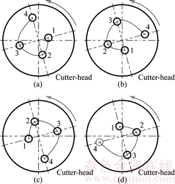
Figure 12 Different layout schemes for each group of cutters
8 Application
Exemplifying the TMB264-311-8030 mm tape TBM cutter-head used in the draw water tunnel project of Liaoning Dahuofang Reservoir; the cutter-head structure is shown in Figure 13. The main structural parameters, geological parameters and excavation parameters are as follows [18]: for the medium square, five-section cutter-head type, the diameter D is 8030 mm and the side length ��T of the central block is 4775 mm. It uses 51 19-inch cutters on the cutter-head, including 8 center cutters, 32 normal cutters and 11 gage cutters; the length ��L and the width ��W of the cutter holes are 495 mm and 360 mm, respectively; the length ��L��, the width ��W�� and the tilt angle ��c1 of the No. 1 muck bucket are 700 mm, 300 mm and 35��, respectively; the length ��L��, the width ��W�� and the tilt angle ��c2 of the No. 2 muck bucket are 900 mm, 300 mm and 80��, respectively. The tunnel is mainly through Grade II and Grade III rock mass; the stratigraphic lithology is mainly mixed rock and belongs to middle hard rock. The uniaxial compressive strength of rock is between 19�C120 MPa; in consideration of safety, the upper limit value 120 MPa is selected, the Brazilian tensile strength is 12 MPa, the punch shear strength is 20 MPa, and the half broken angle of the rock is 1.32 rad; the rotational speed of the cutter-head is 6.32 r/min, and the cutter penetration is 10.8 mm/r.

Figure 13 TMB264-311-8030 mm tape TBM cutter-head
8.1 Determination of profile for cutter-head
The size of the area occupied by the center cutters and the normal cutters on the actual cutter-head is 3458 mm; by calculation, L=557 mm. To determine the profile of the cutter-head, the key is to determine the fillet radius r and installed tilt angle ��.
The HH224335/10 tape bearing is usually used on TBM cutters, so this bearing was chosen as the research object. The corresponding parameters are as follows: l=128.7 mm, y=1.84, e=0.33, fp=2.65. According to Eqs. (1) and (2), the dynamic load of the No. 2 bearing is larger, so the mechanical calculation on the No. 2 bearing was carried out. The ��-P graph is shown in Figure 14.
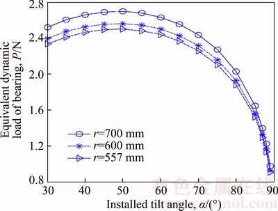
Figure 14 ���CP graph
The graph illustrates that when the installed tilt angle ��<50��, the equivalent dynamic load P increases with the increase of the installed angle range ��; when ����50��, the result is the reverse. The installed angle range of the gage cutters should thus be larger than 50��. This also shows that the equivalent dynamic load increases with the increase of the fillet radius r under the condition of r��L; the fillet radius design should thus not be too large.
When the installed tilt angle ��=74.5��, the fillet radius r=578 mm was calculated by Eq.(4).
8.2 Optimal designs of assembled radii for center cutters and normal cutters
Based on the genetic algorithm, the cutter spacing was optimized according to model 1. Parameters set in the GA are as follows: the population sizes are 50, the crossover probability is 0.8, the mutation probability is 0.2, and iteration times are 100; the rest of the parameters are left at default values. Changing curves of the best fitness value and the best individual in the global search process are shown in Figure 15. This illustrates that when the program is iterated to roughly 50 generations; the optimal solution is gained, verifying the accuracy of the model. The optimal cutter spacing is shown in Table 2.
8.3 Optimal design of installed tilt angle of gage cutters
Based on the genetic algorithm, the installed tilt angle was optimized according to model 2. The parameters set in the GA are as follows: the population sizes are 100, the crossover probability is 0.8, the mutation probability is 0.2, and iteration times are 50, TolCon and TolFun are both 1��10�C7.

Figure 15 Changing curves of fitness function value for best individual and best individual (model 1):
Table 2 Calculation results for optimal cutter spacing

The rest of the parameters are set to default values. Changing curves of the best fitness value and the best individual in the global search process are shown in Figure 16.
Figure 16 illustrates that when the number of iterations reached seven generations, the program terminated because there is no improvement in the fitness value. This is to say, the program reached the optimal solution. The accuracy of the model is fully verified. The optimal tilt angle differences and installed tilt angles are shown in Table 3.
The optimized results and the comparison with the original assembled radiuses are shown in Table 4. This illustrates that when the original cutter-head size and its transition arc area are left unchanged, the optimized radius of the No. 12 cutter has the greatest difference from the original: 25.8 mm, only 0.64% of the cutter-head radius size. Similarly, the optimized radius of the No. 51 cutter has the smallest difference from the original, which is 0 mm; this is consistent with the precondition. Therefore, the established optimization model has evident feasibility and validity.

Figure 16 Changing curves of fitness function value for best individual and best individual (model 2):
Table 3 Calculated results of optimal tilt angle difference

The redesigned result of the cutter-head profile and the disc cutters�� spacing layout pattern for the MB264-311-8030 mm type TBM cutter-head are shown in Figure 17.
Table 4 Results for assembled radius layout of disc cutters
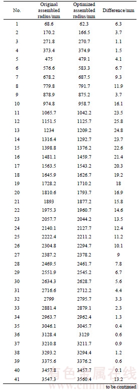
Continued

8.4 Determination of tilt angles of star line groups and solution of non-interference boundary conditions
For the center block area, there are three star line groups, namely 0��, 22.5�� and 45��. For different star line groups, the critical interference polar radius ��x�� and ��x1 are shown in Table 5.
For the edge block area, it can be calculated that ��x1'=11.84��, ��x2'=28.16��, ��x1��=47.82��, ��x2��= 72.73�� by using Eqs. (23) and (24). Therefore, ��x1 must meet the condition 11.84��<��x1<28.16�� or 47.82��<��x1<72.73��. Based on this, five star line groups are created, namely 0��, 13��, 25��, 54�� and 68��. For different star line groups, the critical interference polar radius ��x2 is shown in Table 6.
The critical interference radiuses are shown in Figure 18.
8.5 Layout design of cutters in circumferential direction
The arrangement of the cutters on the cutter- head consists of the radial and circumferential arrangement. GENG et al [17] have established related models: the optimum designs of the polar radii for the center cutters and normal cutters were created based on the principle of equal life; the optimum design of the tilt angles for the gage cutters were established based on the principle of equal wear; and an adaptive design method based on the profile of the cutter-head was proposed. On this basis, the polar angles were optimized by using the cutter circumferential layout method and the cutter-head comprehensive evaluation model, and the resulting cutter layouts are shown in Figure 19.
As shown in Figure 19, there was a total of 13 times arrangement until all cutters were finished. There was no change in the arrangement of the center cutters. For the cutters from No. 9 to No. 51, No. 25 and No. 26 cutters form a group, No. 51 cutter was arranged singly, and every four cutters form a group for the remaining cutters. The grouping situation of the cutters and the optimization result of the polar angles are shown in Table 7. The cumulative calculation result of each index and the comparison with the original cutter-head are shown in Figure 20.
As shown in Figure 20, the cutter-head��s unbalanced radial force in the new cutter layout is 1041.27 kN, an increase of 161.5%, compared with 398.17 kN in the original layout. Similarly, the overturning moment in the new cutter layout is 114.7 kN��m, a decrease of 68.94%, compared with 369.27 kN��m in the original layout. The cutter group��s centroid shift in the new cutter layout is 77.18 mm, an increase of 10.34% compared with 69.95 mm in the original layout. Because the minimization of overturning moment is the key factor in engineering practice, the results prove that the model has feasibility and validity. Nonetheless, considering the unbalanced radial force increases by 161.5%, the new layout is not an optimal result.

Figure 17 Redesign of cutter-head profile and disc cutters��spacing layout pattern
Table 5 Solution of critical interference polar radius (��x�� and ��x1)

Table 6 Solution of critical interference polar radius (��x2)

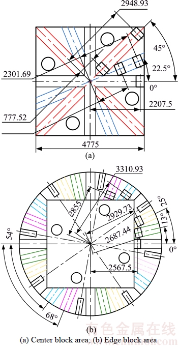
Figure 18 Critical interference radii (Unit: mm):
To make each index better than or approximately equal to the original cutter-head layout result, the appropriate improvement needs to be made in the above layout. As shown in Figure 20, the cutter-head��s unbalanced radial force increases rapidly from the tenth cutter arrangement in the new layout. Therefore, the appropriate adjustments were made for the arrangement of cutters No. 39 to No. 51. The improved layout result is shown in Figure 21 and the calculation results of each index are shown in Figure 22.
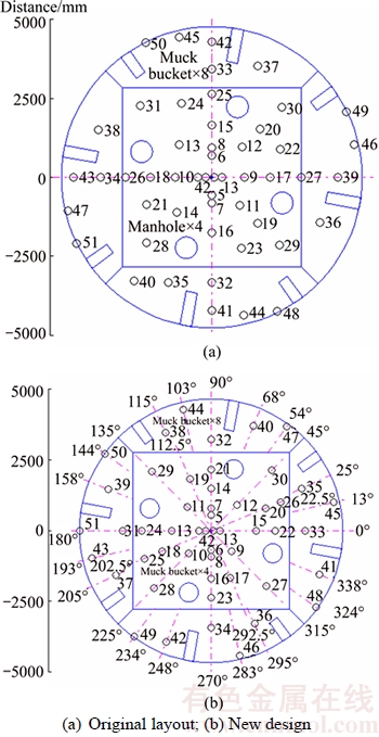
Figure 19 Layout scheme for disc cutters:
As shown in Figure 22, the cutter-head��s unbalanced radial force, the overturning moment and the cutter group��s centroid shift in the improved cutters�� layout are 149.68 kN, 246.61 kN��m and 82.88 mm, respectively. Compared with the original layout, the cutter-head��s unbalanced radial force decreases by 62.41%, the overturning moment decreases by 33.22%, and the cutter group��s centroid shift only increases by 18.48%. This shows that the improved cutter layout is better and has a high value for engineering applications.
Table 7 Grouping of cutters and determination of their polar angles


Figure 20 Cumulative calculation result of each index:
8.6 Finite element analysis of cutter-head
The optimal layout scheme was analyzed by means of FEM. The parameters of the FEM calculation are as follows: the calculated FEM platform is ABAQUS 6.11-1, quadratic tetrahedral elements of type C3D10M is adopted, the density is 7850 kg/m3, the elastic modulus is 2��108 MPa, the Poisson ratio is 0.3, and the yield stress is 345 MPa. For the original layout, the total number of nodes is 90613 and the total number of elements is 47756; for the approved layout, the total number of nodes is 88002 and the total number of elements is 46599. Only the layout pattern has an effect on the cutter-head, regardless of the connecting bodies behind the cutter-head; the full constraints were applied to the reverse side of the cutter-head. In addition, the four faces of each cutter hole were coupled to the center point by the rigid coupling method. The equivalent stress and deformation distribution are shown in Figures 23 and 24 when the vertical force, the rolling force and the lateral force act on the centers of the cutter holes.

Figure 21 Disc cutter layout scheme (improvement)
As shown in Figure 23, the maximum equivalent stress in the original layout is 228.908 MPa, and in the approved layout is 206.371 MPa; the latter is smaller, because the distribution of the cutters in the approved layout is more uniform and scattered, avoiding excessive stress concentration of the cutter-head.

Figure 22 Cumulative calculation result of each index (improvement):
As shown in Figure 24, the deformations decrease gradually from the center to the edge of the cutter-head and the deformation contours are concentric in both layouts. The maximum deformation in the original layout is 0.699 mm and in the approved layout is 0.526 mm; the approved layout gives the cutter-head greater structural stiffness.
The deformation on the positive of the X axis is shown in Figure 25. The deformation is smaller and changes more gently along the radial direction of the cutter-head in the approved layout than in the original layout.

Figure 23 Equivalent stress distribution of cutter-head
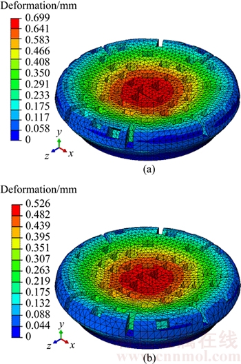
Figure 24 Deformation distribution of cutter-head

Figure 25 Deformation on positive of X axis
9 Conclusions
1) Based on the bearing stress of the outermost gage disc cutter, and according to the relationship between the size of the transition zone, the fillet radius and the installed tilt angle of the cutter-head, an adaptive design method for the profile of the cutter-head was determined.
2) Using a genetic algorithm, based on the principle of equal life, the assembled radiuses of the center cutters and the normal cutters were optimally designed; based on the principle of equal wear, the tilt angles of the gage cutters were optimally designed.
3) The non-interference criteria between the cutters, manholes, muck buckets and welding lines in the radial and circumferential directions were given; the cutter-head comprehensive evaluation model was established by taking the cutter-head��s unbalanced radial force and overturning moment and the cutter group��s centroid shift as evaluation indices, and the plane layout of the cutters was completed; the strength and stiffness of the cutter-head were checked using FEM.
4) The layout results of the cutters show that when the main structure parameters, geological parameters and boring parameters are known, and within a permissible range of error, the design method of this paper has reference value, and can adaptively arrange cutter groups for split type cutter-heads.
References
[1] ZHANG Peng. Design and research on cutter layout and the structural parameters of the cutterhead optimization for TBM [D]. Dalian: School of Mechanical Engineering, Dalian University of Technology, 2009. (in Chinese)
[2] ZHOU Ji-lei. Research on the cutter-head design and analysis of full face TBM [D]. Beijing: School of Energy, Power and Mechanical Engineering, North China Electric Power University, 2011. (in Chinese)
[3] ZHANG Zhao-huang, QIAO Yong-li. Research on the layout of TBM disc cutter [J]. Engineering Mechanics, 2011, 28(5): 172�C177. (in Chinese)
[4] HUO Jun-zhou, SUN Wei, CHEN Jing. Optimal disc cutters plane layout design of the full-face rock tunnel boring machine based on a multi-objective genetic algorithm [J]. Journal of Mechanical Science and Technology, 2010, 24(2): 521�C528.
[5] YU Shi-qiang. The coupling layout design method of cutters group and supporting structure of full face rock TBM [D]. Dalian: School of Mechanical Engineering, Dalian University of Technology, 2013. (in Chinese)
[6] LIU Jian-qin, QIN De-chang, GUO Wei. Research on the cutter layout based on the load analysis [J]. Journal of Tianjin University: Science and Technology, 2016, 49(1): The page number is uncertain. (in Chinese)
[7] GUO Wei, SUN Hong-yan, LIU Jian-qin, SONG Li-wei, SUN Bin. Optimal layout design for disc cutters�� assembled radiuses based on tbm cutter-head profile [EB/OL]. http://www.cnki.net/kcms/detail/12.1127.N.20151222.1343.002.html, 2015-12-22.
[8] SHEN Bin. Research on optimal layout of TBM gage disc cutters combination [D]. Changsha: College of Mechanical and Electrical Engineering, Central South University, 2014. (in Chinese)
[9] QIAO Yong-li. Cutter layout design of full-face rock tunnel boring machine [D]. Beijing: School of Energy Power and Mechanical Engineering, North China Electric Power University, 2009. (in Chinese)
[10] ZHANG Zhao-huang, YE Ding-hai. The model of the disc cutter��s broken-rock and the calculation of its side force [J]. Journal of Basic Science and Engineering, 2011, 28(5): 172�C177. (in Chinese)
[11] ZHANG Hou-mei. Study on numerical simulations of performance of tunnel boring machines (TBM) [J]. Tunnel Construction, 2007, 26(Sup. 2): 1�C7. (in Chinese)
[12] HUO J, SUN X, LI G, et al. Multi-degree-of-freedom coupling dynamic characteristic of TBM disc cutter under shock excitation [J]. Journal of Central South University, 2015, 22: 3326�C3337.
[13] ZHANG Zhao-huang, JI Chang-ming. Analytic solution and its usage of arc length of rock breakage point of disc edge on full face rock tunnel boring machine [J]. Journal of Basic Science and Engineering, 2009, 17(2): 265�C273. (in Chinese)
[14] SHU Biao. Study the wear volume calculation and wear performance of TBM cutter based on abrasive wear [D]. Changsha: College of Mechanical and Electrical Engineering, Central South University, 2014. (in Chinese)
[15] HUO Jun-zhou, SUN Wei, CHEN Jing, ZHANG Xu. Disc cutters plane layout design of the full-face rock tunnel boring machine (TBM) based on different layout patterns [J]. Computers & Industrial Engineering, 2011, 61(4): 1209�C 1225.
[16] SUN Wei, HUO Jun-zhou, CHEN Jing, LI Zhen, ZHANG Xu, GUO Li, ZHAO Hai-feng, ZHAO Yu. Disc cutters�� layout design of the full-face rock tunnel boring machine (TBM) using a cooperative coevolutionary algorithm [J]. Journal of Mechanical Science and Technology, 2011, 25(2): 415�C427.
[17] GENG Qi, WEI Zheng-ying, DU Jun, LU Bing-heng. Cutters�� layout optimization method of the full-face rock tunnel boring machine based on grey relational analysis [J]. Journal of Mechanical Engineering, 2014, 50(21): 45�C53.
[18] ZHANG Wei. Study of cutter layout design of full-face rock tunnel boring machine [D]. Dalian: School of Mechanical Engineering, Dalian University of Technology, 2009. (in Chinese)
(Edited by HE Yun-bin)
���ĵ���
����TBM���̽ṹ�����Ĺ����������
ժҪ��Ŀǰ��������������о��д�������㣬��߹�������������ԣ����̺����Լ��������������������������������õ���ϻ�������Ⱦ�δ�����Ǻ����ӡ�Ϊ�����Щ���⣬���������һ�ֻ��ڵ������������ͺ���Լ�������ĵ��߲��ֵ���Ӧ����Ʒ�����������൶�ߵ��������Ϊ��������ƽ�浶�̵�����������Ʒ���������GA�㷨�����ڵ�����ԭ��͵�ĥ��ԭ�Աߵ�����б�ǽ������Ż���ƣ������˶Թ����������Ͳ���ʱ��������������˿ס��������Լ�����֮�䲻����ı߽����������ø�ָ�����ڽ����β����е�����Ż���߶Ƚ������ٵ�һ���Դ����������˵��̵��ۺ�����ģ�ͣ���ɵ��ߵ������á���MB264-311-8030 mm��TBM����Ϊ��������������������ԭʼ�����IJ�����ȣ�51�ѹ����У���������������25.8 mm������ڵ��̵İ뾶��СΪ0.64%����С�����̵ľ���ƽ����������62.41%���㸲���ؼ�����33.22%������ƫб����������18.48%����ָ�궼���ڻ���Ƶ���ԭʼ���̲��ֽ�������̵�Ӧ���ͱ��ξ�С��ԭʼ���̣���Ч����֤��ģ�͵Ŀ����ԡ�
�ؼ��ʣ�����ʽ���̣��������֣��Ŵ��㷨������������ĥ�����Ͳ���
Foundation item: Projects(51275339, 51575379, 51675374) supported by the National Natural Science Foundation of China; Project(2013CB035402) supported by the National Hi-tech Research and Development Program of China
Received date: 2016-08-03; Accepted date: 2016-10-15
Corresponding author: LIU Jian-qin, PhD, Associate Professor; E-mail: liujianqin@tju.edu.cn; ORCID: 0000-0003-0766-040x

