
Mechanism of localized severe plastic deformation and
damage fracture in fine-blanking using mixed displacement and pressure FEM
XIE Xiao-long(谢晓龙)1, ZHAO Zhen(赵 震)1, YU Song(虞 松)1,
GU Sheng-guang(谷胜光)2, CHEN Jun(陈 军)1, LI Ming-hui(李明辉)1
1. National Die and Mold CAD Engineering Research Center, Shanghai Jiao Tong University, Shanghai 200030, China;
2. Suzhou Dongfeng Fine-blanking Engineering Co Ltd, Suzhou 215004, China
Received 4 November 2005; accepted 12 April 2006
Abstract: A mixed displacement-pressure updated Lagrange FEM was used to simulate the severe plastic deformation, which can overcome shear locking and volume locking. Together with adaptive remeshing technique based on strain gradient and surface curvature, the strain localization in severe plastic deformation can be captured. Schiffmann damage density was used to predict the developments of damage and fracture in sheet metal. The intensive dislocation and slip appear under the action of severe shear deformation, and metallic grains are flattened and elongated in shear band. Because of the existence of large radius of die edge, the flow direction of grains changes, and the grains are elongated and simultaneous. As a result, it is not easy to cut the grains off, and outer surfaces with clean cut are formed.
Key words: fine-blanking; damage; ductile fracture; mixed displacement-pressure FEM; adaptive remeshing
1 Introduction
Strain localization always appears in the form of plastic shear band during the large plastic deformation of metallic material. For most of metal forming processes, the appearance of plastic shear band will cause non-homogeneous deformation and ductile fracture, for example, the drawing breakage of stamping of sheet metal and chevron crack of cold extrusion. But for other forming processes, such as metal blanking, punching, trimming, shearing, plastic shear band will improve the capabilities of local deformation. So it should create appropriate fracture conditions to make cracks propagate along proper directions. As a result, metal components would be produced in the form of shear fracture. Fine-blanking is an advanced precision metal forming technique developed from conventional blanking, and severe plastic deformation is localized in a narrow shear band near cutting clearance of punch and die. Because deformation zone undergoes three dimensional hydrostatic pressures applied by punch, die, v-ring and ejector, and ductile fracture is suppressed, metal components with smooth sheared edges will be manufactured[1]. But if process parameters are not appropriate, insufficient hydrostatic pressures will generate and ductile fracture will appear prematurely.
It is not easy to numerically simulate the localized severe deformation and ductile fracture with FEM, because they are extremely nonlinear problems that bring obstacles to simulation. The calculation accuracy of high order elements is higher, but the efficiency is lower and it is not easy to converge in contact analysis. The volume locking and shear locking will appear in the simulation of large deformation of incompressible materials with low order isoparametric elements, which will produce such unreasonable phenomenon like higher limit loads or no limit loads. Furthermore, because the displacement function of low order isoparametric element is linear, and the distribution of strain in element is constant, therefore, the predicted width of shear band will be increased, pseudo shear stress will be produced and it is difficult to capture the phenomenon of strain localization[2]. Many researchers[2-7] had done some profound researches on the simulations of shear band phenomenon and the severe plastic deformation in shear band. ORTIZ et al[2] proposed a method of bifurcated elements that takes into account band directions. When the onset of localization is detected, the suitably defined shape functions are added to the element interpolation that closely reproduces the localized modes. SLOAN and RANDOLF[4] used higher-order elements with reduced integration or simply used very higher-order elements to simulate shear bands. SIMO and ARMERO [5] proposed the mixed displacement-pressure FEM based on maximum plastic dissipation and multiplicative decomposition of deformation gradient, which could conquer volume locking and shear locking, and reflect strain localization phenomenon. ROLAND and AMIR[6] presented a mixed formulation and used the mixed displacement-pressure triangular elements with adaptive mesh refinements to study the prediction of localization phenomenon in powder-forming processed.
In this study, the updated Lagrange mixed displacement-pressure elasto-plastic FEM, together with adaptive remeshing technique based on strain gradient and surface curvature, is used to research the localized severe plastic deformation in fine-blanking. Furthermore, by using MARC user subroutine, Schiffmann damage work density model which considers the combination of plastic work of matrix and void growth work is added to MARC, and the initiation/propagation of macro cracks is represented by element-deletion approach. The distributions and developing trends of stress, strain and damage are predicted, and the fine-blanking FE model is proved effective in research of the forming mechanism of severe deformation and ductile fracture by experimental result.
2 Mixed displacement-pressure foumula- tions
The mixed displacement-pressure formulation is based on the maximum plastic dissipation and the multiplicative decomposition of the deformation gradient. The mixed formulations decompose the stress tensor into deviatoric and hydrostatic components[8]:
 (1)
(1)
where sij is the deviatoric stress and p=-1/3tr(σ).
For metallic material, a volumetric incompressible limit is introduced:

 (2)
(2)
where 
 , Kv is the bulk modulus of material.
If the accelerations are neglected, the equilibrium equation can be presented as
 sij-
sij- +b=0 (3)
where b is the body force acceleration.
So J2 rate based displacement-pressure mixed formulation can be given by
 ?sdΩ
?sdΩ (4)
(4)
Discretization of Eqns.(2) and (4) using shape functions Nu and Np for the displacement and pressure fields using Newton-Raphson iteration scheme result in
 (5)
(5)
In the above equation, Ks is the deviatoric or shear stiffness matrix, and matrix Q corresponds to the discretization of gradient operator , and
, and  . fu and fp are consistent nodal load vector and pressure obtained in displacement formulation.
A quadrilateral five-node mixed displacement and pressure finite element is shown in Fig.1. Because there is hydrostatic pressure in the centre of element, the displacement function will not be linear. The degrees of freedom of inner pressure node will be condensed when whole stiffness matrix is assembled, the degrees of freedom of four corner nodes will replace those of inner node by using bilinear interpolation function, and the amount of degrees of freedom in whole equilibrium equation will not increase. Consequently, it could overcome shear locking and volumetric locking problems, overcome pseudo shear stress, and capture strain localization phenomenon accurately.
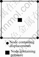
Fig.1 Quadrilateral five-node mixed displacement and pressure finite element
3 Modeling of ductile damage and fracture
In fine-blanking, once plastic shear band is formed by strain localization, it will either produce clean-cut surface or surface with shear fracture, depending on the developing tendency of material damage in shear band (see Fig.2). Generally speaking, metallic materials are mostly polyphase materials containing inclusions and diphase particles whose ingredients and mechanics beha- viors are different and the levels of combination with matrix are different as well. When the applied loads of material reach a certain level, voids will nucleate around inclusions and diphase particles. With the degree of deformation developing, voids will grow up and coalesce, so micro cracks initiate. Up to now, many researchers have put forward their damage and fracture models, such as GORSON, TVERGAARD and NEEDLEMAN, MCCLINTOCK, RICE and TRACEY[9-12], but those models regarded the critical void volume ratio or critical void growth ratio as material constants, and had no practical value. In some cases no growth and coalescence of voids occur under pure shear conditions, but fracture initiates[13], so the growth of voids and the level of plastic deformation should be considered in appropriate model. Considering the total work at ductile fracture is the sum of plastic deformation work of matrix and damage work of voids growth, SCHIFFMANN et al[13] proposed a damage work density model:
 (6)
(6)
where Wd is the critical damage work density when crack occurs and it is regarded as material constant like yielding stress for a given material, σm is the hydrostatic stress, σv is the effective stress, and  is the equivalent strain when cracks occur. α is material constant, and α≈0.5 for most steels[13]. In order to obtain the critical value for SS400 steel which is low carbon cold rolled steel used in simulation, SS400 steel metal was placed in fine-blanking tool, and performed blanking operation. When visible macro-cracks appeared on the sheet surface, the punch displacement was measured. Then the damage work was calculated in Marc software with the same progress parameters. When the punch in simulation reached the distance that cracks appeared in experiment, the calculated value was the critical damage density work. As a result, we got the critical value 1 315 MJ/mm3 for SS400 steel.
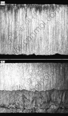
Fig.2 Shear surfaces of fine-blanking: (a) Surface without ductile fracture; (b) Surface with ductile fracture
4 Modeling of numerical simulation
The fine-blanking 2D model is shown in Fig.3, and the parameters of simulation are shown in Table 1. The punch, die, v-ring and ejector are defined as rigid bodies, and the sheet metal is defined as elasto-plastic body. In order to obtain sufficient hydrostatic pressure in shear zone, double v-rings are adopted. The element type is quadrilateral 5-node mixed displacement and pressure element, and the adaptive remeshing technique[14] based on strain gradient and surface curvature is used to determine the degree of refinement of meshes, which is shown in Fig.4. In order to reduce the volume loss of elements deletion when cracks develop, the edge length of meshes near cutting edges are controlled in 0.01 mm. The simulation is divided into two load cases, first, the v-ring presses into sheet metal and ejector applies ejector forces, second, the punch presses into sheet metal, and plastic shear band forms gradually.
Table 1 Process parameters of fine-blanking
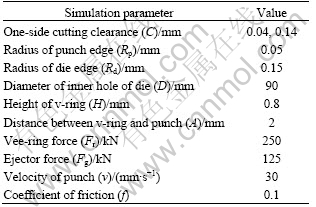

Fig.3 2D model of fine-blanking
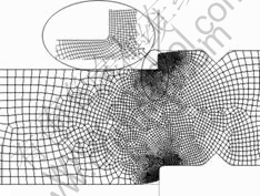
Fig.4 Local mesh refinement
In fine-blanking, the velocity of punch is slow, so the influences of strain rate and temperature on deformation can be neglected. The material in simulation is SS400 steel, and the necessary material data are obtained through standard tensile test of sheet metal, then the flow stress curve of SS400 steel under large deformation is obtained by extrapolation of Voce hardening material model (see Fig.5).
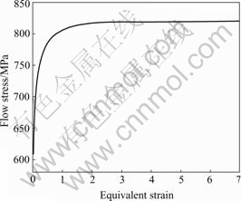
Fig.5 Flow stress curve of SS400 steel
5 Results and analysis
5.1 Analysis on development of shear band
The distribution of σm when v-ring presses into 0.6 mm is shown in Fig.6(a). Materials near v-rings are compressed and the hydrostatic pressure is extended into plastic shearing zone, so a good hydrostatic state is created before fine blanking. The distribution of σm when the punch presses into 20% of sheet thickness is shown in Fig.6(b). The values of σm near punch edge and die edge are much larger, which are dangerous regions where cracks occur. Good hydrostatic state is still preserved in fine blanking shearing zone under the combined actions of v-ring, punch, die and ejector, so the generation of fracture is restrained. Hydrostatic pressure σm plays an important role in fine blanking, so if σm is lower, the degree of metal deformation will be higher when fracture occurs.
The development of  distributions in plastic shear band is illustrated in Fig.7. When punch presses into 5% of sheet thickness, strain localization forms, which develops in the direction along the punch edge towards die edge, and the plastic deformation zone is localized near the narrow cutting clearance. Therefore, this is the initial stage that plastic shear band forms. From Fig.7(b) we can see, when punch presses into 50% of sheet thickness, severe plastic deformation occurs in shear band, and the maximum develops to 5.8 near punch edge, because the radius of punch edge is very small, and the degree of revolving and stretching of metal grains is largest here. In Fig.7(c), when punch presses into 100% of sheet thickness, the maximum develops to 9.2, the metal in severe plastic deformation zone is stretched into a line by the narrow cutting clearance and break, so burrs of part form. Apparently, the mechanism for part’s separation with sheet metal is different from that of conventional blanking. Two cracks initiating near punch edge and die edge will link up under large cutting clearance of conventional blanking, and large fracture zone and burrs will be generated. But for fine-blanking, ductile fracture is suppressed by hydrostatic pressure and side surfaces with full clean cut are generated by shear formation. Eventually, the part is obtained when punch penetrates the sheet metal completely.
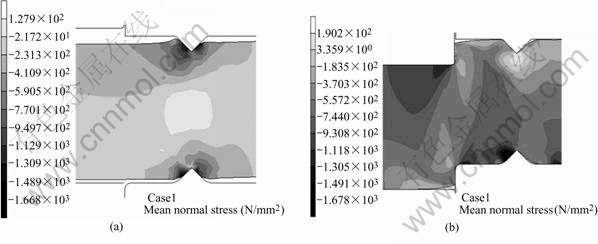
Fig.6 Hydrostatic stress at different stages: (a) V-ring presses into 0.6 mm; (b) Punch presses into 20% of thickness
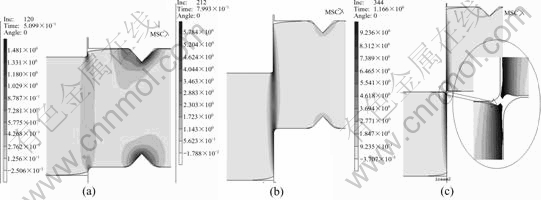
Fig.7 Distributions of equivalent strain at different stages: (a) 5% of thickness; (b) 50% of thickness; (c) 100% of thickness
5.2 Experimental observation and analysis
In order to observe and research the severe deformation in shear band of fine-blanking, a photoactive etching method[14,15] was adopted. The material of specimen was SS400 steel with the thickness of 5 mm. Firstly the specimens were cut off at symmetric planes and meridian planes were polished. Secondly the chessboard-pattern grids were etched on meridian planes of specimens, which are shown in Fig.8(a). The etched grid of 0.25 mm×0.25 mm was fine enough to observe the severe deformation. Then each pair of specimens was glued and clamped. The experiment was performed on 3 200 kN fine-blanking press, and the process parameters of this experiment were the same as those in simulation.
Figs.8(b-d) show the grids deformation when punch presses into 15%, 45% and 75% of sheet thickness, respectively. At the initial stage of strain localization, the girds in shear band move and rotate slightly with the shape’s changing from square to diamond. With the penetration of punch into working material, the girds distort gradually, and are limited in a narrow shear band. When punch penetrates into 75% of sheet thickness, the grids are distorted severely, and the shape of shear band is similar as that in simulation. Although grids are heavily distorted, they are still continuous and not cut off, which proves that fine-blanking is a continuous plastic deformation process and side surfaces with full clean cut are generated due to the existence of plastic shear band. From the pictures we also can see that, die-roll increases along with the pressing of punch at initial stage, because of the stretching and bending actions and continuity of materials. But the die-roll will not increase apparently at middle and final stages because the hardening of materials suppresses the formation of die-roll.
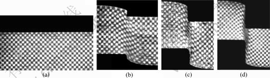
Fig.8 Etched grids before and after deformation: (a) Grids made through photoactive etching; (b)-(d) Deformed grids after punch pressed into 15%, 45%, 75% of thickness, respectively
Fig.9(a) shows the metallographic photo when punch presses into 50% of sheet thickness. The intensive dislocation and slip appear under the action of severe shear deformation, and metallic grains are flattened and elongated near punch edge. Fig.9(b) shows the metallographic photo of 90% of penetration. Metals below punch and above die still keep un-deformed state, and grains in plastic shear band continue to be elongated because of strong metal flow. Because of the existence of large radius of die edge, the flow direction of grains changes, and grains are elongated and simultaneous. As a result, it is not easy to cut the grains off, and outer surfaces with clean cut are formed.
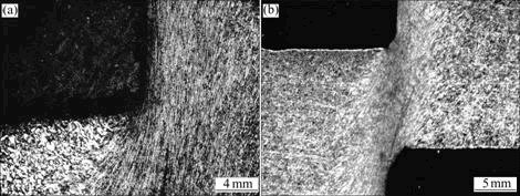
Fig.9 Metallographs under localized severe plastic deformation: (a) Near punch, pressed into 50% of thickness; (b) Pressed into 90% of thickness
5.3 Analysis of ductile damage and fracture
Schiffmann damage work density Wd reflects the role of hydrostatic pressure for suppressing or accelerating ductile fracture of materials, and it can not only represent the instantaneous state of damage, but also reflect the deterioration effect of stress-stain history on materials. Fig.10 shows the distributions of Wd when punch presses into 25%, 50% and 99% of sheet thickness, respectively. The distribution of Wd is like that of , and reflects the localization of damage generated by severe deformation in shear band. Along with the pressing of punch, the degree of local damage is larger and larger, and the maximum value develops from 340.5 to 1 290 mJ/mm3, which approaches critical value.
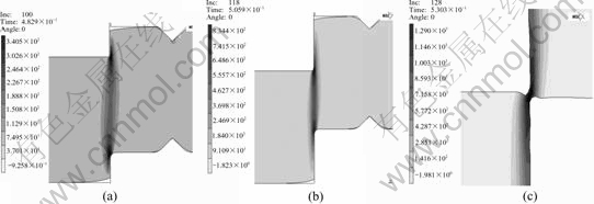
Fig.10 Distributions of Schiffmann damage work density at different stages: (a) 25% of thickness; (b) 50% of thickness;(c) 99% of thickness
Fig.11 shows the developing tendency of Wd near punch edge and die edge under different cutting clea- rances. When the cutting clearance is 0.04 mm which is 0.8% of sheet thickness, the damage work density increases slowly either near punch edge or near die edge at all stages, because smaller hydrostatic stresses produced by narrower clearance suppress the growth of voids, although the plastic deformation work increases, the damage work does not increase too much. But when the cutting clearance is 0.14 mm, the damage work increases slowly at the initial stage, but quickly at the middle stage because of the larger cutting clearance. Furthermore, the damage work near punch edge is larger than that near die edge for the reason of large hydrostatic stress generated by sharp punch edge.
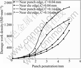
Fig.11 Distributions of damage work density under different cutting clearances
Fig.12 shows the developments of macro crack in numerical simulation and experiment when the cutting clearance is 0.14 mm. Macro crack appears near punch edge when the punch displacement is 3.6 mm and the damage work density reaches the critical value 1 315 MJ/mm3. After crack appears, it propagates from punch edge to die edge in the direction of maximum shear stress. The position and developing direction of crack coincide with the experimental results.

Fig.12 Propagation of crack in shear band when punch presses into 3.6 mm of sheet thickness: (a) Simulation result;(b)Experimental result
5.4 Analysis of fine-blanking cutting force
Fig.13 shows the predicted fine-blanking cutting forces curves obtained from numerical simulation. The deformation process can be divided into three stages. Firstly, plastic shear band initiates. At this stage, elastic deformation of sheet metal turns into plastic deformation, and the degree of material hardening is aggravated. Therefore, cutting force increases rapidly, and arrives at peak value. At the second stage, the effective area of bearing cutting force of sheet metal decreases continuously, when its influence on cutting force exceeds the influence of material hardening on cutting force, so cutting force decreases gently. But the phenomenon does not occur that cutting force decreases rapidly because ductile fracture is generated prematurely in conventional blanking. At the third stage, because the damage of materials in shear band is aggravated and the softening of material occurs, the cutting force decreases rapidly. Finally, the part separates from sheet metal, and the cutting force becomes zero.
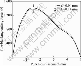
Fig.13 Predicted fine-blanking cutting forces curves under different cutting clearances
6 Conclusions
1) A fine-blanking simulation model is set up based on the updated Lagrange mixed displacement-pressure elasto-plastic FEM and adaptive remeshing technique. Comparing the result of simulation with the experimental result, it is proved that the model is an effective model, and can predict material flow of localized severe plastic deformation accurately.
2) It is proved by experiment that Schiffmann damage work density model is a reliable model to predict damage development in fine-blanking. It is also proved that element-deletion approach is successfully used to predict the initiation and propagation of cracks in severe deformation in fine-blanking.
3) Hydrostatic pressure plays an important role in fine blanking. If it is lower, the degree of metal deformation will be higher when fracture occurs. When the cutting clearance is small, the damage work density increases slowly either near punch or die edge, because smaller hydrostatic stresses produced by narrower clearance suppress the growth of voids, although plastic deformation work increases, the damage work does not increase too much. Furthermore, the damage work density near punch edge is larger than that near die edge for the reason of large hydrostatic stress generated by sharp punch edge. But when the cutting clearance is larger, it increases slowly at the initial stage, but quickly at the middle stage because hydrostatic stress increases rapidly. So crack appears near punch edge, and propagates towards die edge in the direction of maximum shear stress. The intensive dislocation and slip appear under the action of severe shear deformation, and metallic grains are flattened and elongated in shear band. Because of the existence of large radius of die edge, the flow direction of grains changes, and grains are elongated and simultaneous. As a result, it is not easy to cut the grains off, and outer surfaces with clean cut are formed.
References
[1] LANGE K, MUKHOTY A, BIRZER F, HOEFEL P, SINGER H. Cold Forming and Fineblanking―A Handbook on Clod Processing, Material Properities, Component Design [M]. Switzerland: Edelstahlwerke Buderus AG, 1997.
[2] ROTIZ M, LEROY Y, NEEDLEMAN A. A finite element method for localized failure analysis [J]. Computer Methods in Applied Mechanics and Engineering, 1987, 61: 189-214.
[3] LIU Y Q, CHEN S H, WANG S L, HU P. Numerical simulation for the necking development and the shear band fracture under plane strain tension of ductile materials [J]. Journal of Mechanical Strength, 1994, 16(3): 55-60.
[4] SLOAN S W, RANDOLPH M F. Numerical prediction of collapse loads using finite element methods [J]. International Journal for Numerical and Analytical Methods in Geomechanics, 1982, 6: 47-76.
[5] SIMO J C, ARMERO F. Geometrically non-linear enhanced strain mixed methods and the method of incompatible modes [J]. International Journal for Numerical Methods in Engineering, 1992, 33: 1413-1449.
[6] ROLAND W L, AMIR R K. Numerical analysis of strain localization in metal powder-forming processes [J]. International Journal for Numerical Methods in Engineering, 2001, 52: 489-501.
[7] CHEN Z H, TANG C Y, LEE T C, CHAN L C. Numerical simulation of fine-blanking process using a mixed finite element method [J]. International Journal of Mechanical Sciences, 2002, 44: 1309-1333.
[8] PASTOR M, QQUECEDO M, ZIENKIEWICZ O C. A mixed displacement-pressure formulation for numerical analysis of plastic failure [J]. Computers & Structures, 1997, 62(1): 13-23.
[9] GURSON A L. Continuum Theory of ductile rupture by void nucleation and growth(I): yield criteria and flow rules for porous ductile media [J]. Engineering Material Technology, 1977, 99: 2-15.
[10] TVERGAARD V, NEEDLEMAN A. Analysis of the cup-cone fracture in a round tensile bar [J]. Acta Metall, 1984, 32 (1): 157- 169.
[11] MCCLINTOCK F A. A criteria for ductile fracture by the growth of holes [J]. J Appl Mech Trans ASME, 1968, 35: 363-371.
[12] RICE J R, TRACEY D. On the ductile enlargement of voids in triaxial stress fields [J]. J Mech Phys Solids, 1969, 17: 201-217.
[13] SCHIFFMANN R, BLECK W, DAHL W. The influence of strain history on ductile failure of steel [J]. Computer Materials Science, 1998, 4: 142-147.
[14] CHEN Jun, ZHANG Xiang, RUAN Xue-yu. Research of couple of key techniques in numerical simulation of 3D metal extrusion process [J]. The Chinese Journal of Nonferrous Metals, 2002, 12(6): 1119-1122.(in Chinese)
[15] ZHENG Peng-Fei. Finite Element Analysis of the Combined Fine Blanking and Extrusion Process [D]. Hong Kong: Hong Kong Polytechnic University, 2000.
[16] CHEN Zhang-Hua. Process Modeling of Fine-Blanking Using Thermo-Mechanical Coupling Method [D]. Hong Kong: Hong Kong Polytechnic University, 2002.
Foundation item: Project(50505027) supported by the National Natural Science Foundation of China
Corresponding author: ZHAO Zhen; Tel: +86-21-62813430-8116; E-mail: zzhao@sjtu.edu.cn
(Edited by YUAN Sai-qian)

