J. Cent. South Univ. Technol. (2010) 17: 1243-1246
DOI: 10.1007/s11771-010-0626-x
Sensorless control for hysteresis compensation of
AFM scanner by modified Rayleigh model
PARK J K1, MOON W K2
1. Department of Mechanical Engineering, Changwon National University, Changwon 641-773, Korea;
2. Department of Mechanical Engineering, Pohang University of Science and Technology, Pohang 790-784, Korea
? Central South University Press and Springer-Verlag Berlin Heidelberg 2010
Abstract: A novel modified Rayleigh model was developed for compensating hysteresis problem of an atomic force microscope (AFM) scanner. In high driving fields, piezoelectric actuators that integrated a scanner have severe hysteresis, which can cause serious displacement errors. Piezoelectric hysteresis is from various origins including movement of defects, grain boundary effects, and displacement of interfaces. Furthermore, because its characteristic is stochastic, it is almost impossible to predict the piezoelectric hysteresis analytically. Therefore, it was predicted phenomenologically, which means that the relationship between inputs and outputs is formulated. The typical phenomenological approach is the Rayleigh model. However, the model has the discrepancy with experiment result as the fields increase. To overcome the demerit of the Rayleigh model, a modified Rayleigh model was proposed. In the modified Rayleigh model, each coefficient should be defined differently according to the field direction due to the increase of the asymmetry in the high fields. By applying an inverse form of this modified Rayleigh model to an AFM scanner, it is proved that hysteresis can be compensated to a position error of less than 5%. This model has the merits of reducing complicated fitting procedures and saving computation time compared with the Preisach model.
Key words: piezoelectric stack actuator; hysteresis compensation; Rayleigh model; atomic force microscopy
1 Introduction
Hysteresis of a scanner is one of main causes of image distortion in atomic force microscope (AFM) [1]. The hysteresis of an AFM scanner can cause serious displacement errors (10%-15%), which disallow precise position control of a sample. Its source is known to be primarily from piezoelectric hysteresis of a piezoelectric ceramic actuator. Most piezoelectric actuators have piezoelectric, ferroelectric and ceramic properties simultaneously [2]. Moreover, defects are distributed randomly over the whole material. For this reason, it is too difficult to derive an exact hysteresis model composed of several physically meaningful material coefficients. To date, various efforts have been made to minimize the hysteresis problem [1, 3-5]. One is charge control, which has bandwidth problem and saturation problem for long travel range [3-4]. The other better solution is to use positioning sensors such as a linear variable differential transformer (LVDT) or a capacitive sensor [5]. Although this approach can eliminate the problem, it has high cost and also needs an appropriate mathematical model for better performance. Therefore, in this work a phenomenological model consisting of physically meaningful material coefficients to utilize feedforward and signal control without sensors was investigated.
The classical Rayleigh law is the most typical phenomenological approach for hysteresis model under subcoercive and nonswitching fields [2, 6-7].
 (1)
(1)
 (2)
(2)
where P is the polarization; Pm is the maximum polarization; S is the strain; Sm is the maximum strain; εi is the initial permittivity; di is the initial piezoelectric constant; αp and αs are nonlinear Rayleigh coefficients related to irreversible domain wall motion and defect distribution in the crystal microstructure, and can be obtained by curve fitting between the model and experimental data [2]; E is the electric field; Em is the maximum electric field; diEm and εiEm describe reversible displacement of domain walls; and αEm2 describes irreversible displacement of domain walls.
When the hysteresis curve of the whole field is predicted by using one equation, it has the discrepancy with experiment result as external fields become larger. Therefore, a modified Rayleigh model is proposed. In this model, each coefficient should be defined differently according to field direction to consider the increase of the asymmetry in the high fields. In addition, according to various electromechanical experiments by our experimental setup, increasing and decreasing rate of the displacement or charge were the same regardless of the magnitude of the voltage. From this result, it can be derived that the modified Rayleigh model is useful in unipolar driving fields. By using an inverse form of this simple and effective model, it is shown that the hysteresis problem of an XY AFM scanner is suppressed to a position error of less than 5%.
2 Experimental
To measure various electromechanical coupling characteristics simultaneously and check the phenomenological shape of hysteresis, two measurement devices were installed. Firstly, charge-voltage curves were measured by using a Sawyer-Tower circuit. Secondly, displacement-voltage curves were measured by a laser doppler velocimetry (Polytec LDV) with 2 nm resolution. Additionally, Labview PXI system was used for data acquisition (5122 board) and waveform generation (5422 board). From this measurement setup (see Fig.1), it is known that the electrical and mechanical properties are closely related to each other. Figs.2-3 show the original hysteresis curves. The time response of displacement is similar to the shape of a shark fin, which makes displacement error of more than 10%. This experiment shows that upward and downward curves of the hysteresis are not symmetrical to each other. This means that the classical Rayleigh model should be modified to be applied to the actuator.
3 Operational principle
Although the classical Rayleigh law can predict the hysteresis curve of the whole subfield by using one equation, the shape of the modeled curve is symmetrical. The asymmetry of the hysteresis curve increases with field intensity and direction. In the low fields, the quadratic equation can be determined only with one coefficient. However, as the fields increase, the polarization and displacement curves measured in piezoelectric stack ceramics under subswitching field intensities are not always symmetrical, in contrast to the predictions of the Rayleigh model. Coefficient should be defined differently according to field direction (i.e., upward or downward).
Another important point is the relationship between polarization and strain. The almost linear relationship appears under unipolar drive according to our experiments. This means that displacement can be predicted by charge. In other words, displacement can be controlled by using charge based model in response of voltage. In this way, the displacement could be controlled without using any other sensors.
In order to convert the Rayleigh model into a relationship between the voltage and the displacement or charge, Eq. (3) is substituted into Eqs.(1)-(2).
 (3)
(3)
where δ is the displacement; V is the input voltage; and t is the thickness of actuator. Then, coordinate transformation is necessary for application under unipolar drive. So, replacing E with E-Em, D with D-(εi+αEm)Em, and S with S-(di+αsEm)Em, in Eqs.(1)-(2), Eqs.(4)-(5) can be derived:
 (4)
(4)
 (5)
(5)
where q is charge; and coefficients are expressed with
 a is electrode area; and C is the capacitance of the actuator.
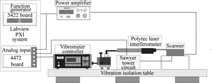
Fig.1 Experimental setup to measure electromechanical properties
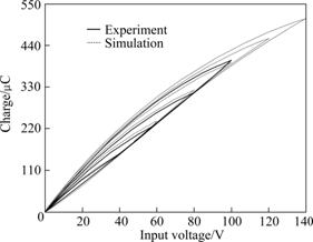
Fig.2 Comparison between modified Rayleigh model and experimental data (charge curves)
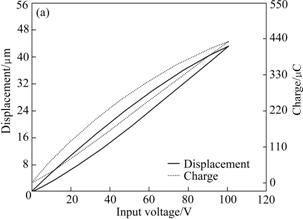
Fig.3 Uncompensated response of scanner (Charge and displacement curve with respect to input voltage)
For a more accurate phenomenological model, each of the increasing and the decreasing coefficients should be defined differently. That is, Eq. (4) is divided into two equations as follows:
 (6)
(6)
In Eq.(6), all coefficients except Rayleigh coefficients and initial permittivities are given by input values. To determine initial permittivities and Rayleigh coefficients, phenomenological law should be used. Firstly, the Rayleigh coefficient of the increasing curve can be determined simply by fitting with the experimental result at the maximum voltage because all increasing reversal curves trace the same trajectory. Although all decreasing curves have different paths with respect to different maximum voltages as shown in Fig.2, they also have the same slope by the reversal law and can be overlapped by parallel movement [8-13]. Based on this result, the Rayleigh coefficient of the decreasing curve can be also determined just by fitting experimental results at the maximum voltage. Therefore, Rayleigh coefficients can be determined by comparing Eq.(7) with experimental results
 (7)
(7)
Initial permittivities can be calculated by using the value of turning point at which the increasing curve meets the decreasing one. In other words, Eq.(9) is derived by calculating Eq.(8) and those values can be determined:
 (8)
(8)
 (9)
(9)
By this procedure, if all coefficients are calculated by only fitting maximum increasing and decreasing curves to experimental results, the trajectory of hysteresis curves in all local fields that have the same starting point can be predicted, as shown in Fig.2.
4 Results and discussion
Firstly, it is verified that hysteresis of the stack actuator can be predicted by using the modified Rayleigh model (Fig.2). So, the same method was adopted for the AFM scanner. Fig.4 shows the compensated graph based on the charge model. The charge and displacement graphs are almost linear, which means that the desired trajectory can be achieved and the hysteresis problem can be suppressed. Nevertheless, the displacement curve has a little hysteresis error. Hence, the compensation was performed based on the displacement model. The result shows that some of the displacement hysteresis can be reduced (Fig.5). Additionally, the model can be applied at different frequencies (Fig.6). Generally, the shape of hysteresis curve is almost similar in quasistatic condition because dynamic characteristics originated from mass effect seldom appear in that condition. Moreover, according to the mechanism of our model and various electromechanical experiments, it is always possible to expect the hysteresis curve of the similar shape. From that reason, it can be concluded that the modified Rayleigh model can be used in the broad frequency range of quasistatic condition.
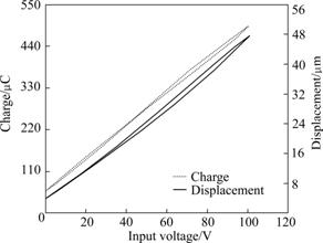
Fig.4 Compensated response of scanner based on charge model showing charge and displacement response with respect to maximum input voltage of 100 V at 1 Hz (Charge and displacement are converted into output voltage to compare shape of two responses)
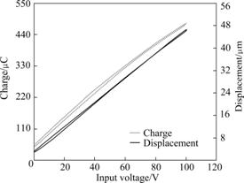
Fig.5 Compensated response of scanner based on displacement model at 1 Hz
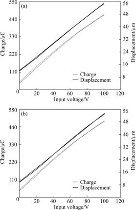
Fig.6 Compensated response of scanner based on displacement model with respect to maximum input voltage of 100 V at 2 Hz (a) and 0.5 Hz (b)
5 Conclusions
(1) The method of reducing the hysteresis problem of the scanner is investigated using a novel modified Rayleigh model. AFM scanner and piezoelectric hysteresis that is the main factor of the hysteresis problem appearing in the scanner operation, are introduced. The classical Rayleigh law with a practically used piezoelectric stack actuator is analyzed phenomenologically to find the discrepancy between the law and the response of the actuator. The modified Rayleigh model that can predict the piezoelectric hysteresis in unipolar driving fields more accurately is established. The model is applied to the AFM scanner.
(2) The hysteresis of the scanner can be also predicted. By applying an inverse form of this modified Rayleigh model to an AFM scanner, hysteresis can be compensated to yield a position error less than 5%.
(3) This model can predict the hysteresis curves in all subfields only by one fitting procedure, different from other models having complicated fitting procedures. The model can be useful for feedforward and signal control in unipolar driving fields and applied at different frequencies in a quasi-static loading condition.
References
[1] CROFT D, SHED G, DEVASIA S. Creep, hysteresis, and vibration compensation for piezoactuators: Atomic force microscopy application [J]. Journal of Dynamic Systems, Measurement, and Control, 2001, 123: 35-44.
[2] UCHINO K. Ferroelectric devices [M]. New York: Marcel Dekker, 2002: 1-12.
[3] FURUTANIY K, URUSHIBATA M, MOHRI N. Displacement control of piezoelectric element by feedback of induced charge [J]. Nanotechnology, 1998, 9: 93-98.
[4] YI K A, VEILLETTE R J. A charge controller for linear operation of a piezoelectric stack actuator [J]. IEEE Transactions on Control System Technology, 2005, 13: 517-526.
[5] SCHITTER G, STEMMER A. Model-based signal conditioning for high-speed atomic force and friction force microscopy [J]. Microelectronic Engineering, 2003, 67: 938-944.
[6] DAMJANOVIC D, DEMARTIN M. The Rayleigh law in piezoelectric ceramics [J]. Journal of Physics D: Applied Physics, 1996, 29: 2057-2060.
[7] TAYLOR D V, DAMJANOVIC D. Evidence of domain wall contribution to the dielectric permittivity in PZT thin films at sub-switching fields [J]. Journal of Applied Physics, 1997, 82: 1973-1975.
[8] SMITH S T. Flexures elements of elastic mechanism design [M]. Gordon and Breach, 2002.
[9] ZAPPERI S, MAGNI A, DURIN G. Microscopic foundations of the rayleigh law of hysteresis [J]. Journal of Magnetism and Magnetic Materials, 2002, 242: 987-992.
[10] BERTOTTI G. Hysteresis in magnetism [M]. New York: Academic Press, 1998: 30-62.
[11] MAYERGOYZ I D. Mathematical models of hysteresis [M]. Berlin: Springer-Verlag, 1991: 15-24.
[12] TROLIER S, GHARB N B, DAMJANOVIC D. Piezoelectric nonlinearity due to motion of 180 degrees domain walls in ferroelectric materials at sub-coercive fields: A dynamic poling model [J]. Applied Physics Letter, 2006, 88: 202901.
[13] PARK J, MOON W. Hysteresis compensation of piezoelectric actuators: The modified Rayleigh model [J]. Ultrasonics, 2010, 50: 335-339.
(Edited by CHEN Wei-ping)
Foundation item: Project supported by the Second Stage of Brain Korea 21 Project; Project supported by the Korea Science and Engineering Foundation (KOSEF) through the National Research Laboratory Program Funded by the Ministry of Science and Technology; Project supported by Changwon National University, Korea
Received date: 2010-06-29; Accepted date: 2010-09-22
Corresponding author: PARK J K, PhD; Assistant Professor; Tel: +82-55-2133608; E-mail:chong@changwon.ac.kr

