
Inner-product of strain rate vector through direction cosine in coordinates for disk forging
ZHAO De-wen(赵德文), JIN Wen-zhong(金文忠), WANG Lei(王 磊), LIU Xiang-hua(刘相华)
State Key Laboratory of Rolling and Automation, Northeastern University, Shenyang 110004, China
Received 11 January 2006; accepted 19 May 2006
Abstract: A new linear integration for plastic power was proposed. The effective strain rate for disk forging with bulge was expressed in terms of two-dimensional strain rate vector, and then its direction cosines were determined by the ratio of coordinate increments. Furthermore, inner-product of the vector for plastic power was term integrated by term and summed. Thereafter, through a formula for determination of bulge an analytical solution of stress effective factor was obtained. Finally, through compression tests, the calculated results of above formula were compared with those of Avitzur’s approximate solution and total indicator readings of the testing machine. It is indicated that the calculated compression forces are basically in agreement with the measured ones if the pass reduction is less than 13.35%. However, when the reduction gets up to 25.34% and 33.12%, the corresponding errors between the calculated and measured results also get up to 6% and 13.5%, respectively.
Key words: disk forging; bulge; strain rate vector; direction cosine; inner-product; analytical solution
1 Introduction
Since friction over the surface of disk forging lowers the velocity at the surface, causing the center y=0 to move faster with a resultant bulge as shown in Fig.1(a). Therefore, this velocity gradient from the surface to the interior brings about a shear strain rate. It is the bulge that makes the forging more difficult to be analyzed[1].
Numerical methods[2], including FEM[3,4] and UBET[5], have been successfully used to solve the forging with bulge in recent years. Heretofore BARAYA and JOHNSON[6] ever analyzed bar forging with the help of triangular velocity field but did not take into account barreling or bulging. AVITZUR[7, 8] used upper bound continuous velocity field to determine the extent of the barreling developed during disk forging. JUNEJA [9] successfully analyzed the forging of polygonal discs.
In this paper the disk forging with bulge was solved by so called inner-product of strain rate vector[10,11] with direction cosines determined by coordinate increments. The final results of this solution were compared with those of AVITZUR’s immediate integration[7,8] and those of measured by the compression test.
2 Deformation power
2.1 Strain rate tensor field
Assuming that vr varies exponentially with the y coordinate as shown in Fig.1(b), the kinematically admissible velocity field becomes[7, 8]
 (1)
(1)
where b is the parameter of bulge.
From Eqn.(1), the strain rate field is obtained as
 (2)
(2)

Fig.1 Schematic diagram of disk forging with bulge: (a) Bulge; (b) Disk forging
The detail deduction of above equations can be seen in Refs. [7,8]. And the ratio of coordinate increments in Eqn.(2) satisfies the following relationship:
 (3)
(3)
2.2 Inner-product of strain rate vector
The effective strain rate in the integrand of plastic power is expressed by inner-product of strain rate vector, that is
 (4)
(4)
where  is strain rate vector and
  unit vector. From the definition of vector inner-product, we can obtain

where l1, l2 are direction cosines of strain rate vector determined by the ratio of coordinate increments. The formulae for determination of l1 and l2 are

 (5)
(5)
The term by term integration is used for Eqn.(4). From Eqn.(5) and dV=2πrdrdy, we can obtain

where I1 and I2 are the term by term integrated results of strain rate vector.
Substituting the above integrated results into Eqn.(4), we obtain
 (6)
(6)
where
 .
.
2.3 Friction losses
According Eqn.(1), the friction losses is
 (7)
(7)
3 Total power and minimization
3.1 Total power
Substitution of Eqns.(6) and (7) into J*= , the upper bound total power is
 (8)
(8)
Let
 (9)
(9)
Differentiating Eqn.(8) with respect to b and equating the derivative to zero, we can obtain the following equation
 (10)
(10)
where 
The relationship between b and m is shown in Fig.2. It can be seen that for different ratios of r0 to h, the maximum m occurs with the variation of b. When the value of b is less than b (corresponds to the maximum m), the value of m increases with increase of r0/h or b.
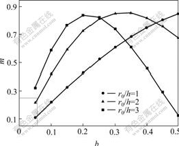
Fig.2 Relationship between b and m for different ratios of r0 to h
When value of b is greater than b, corresponds to the maximum m, inverse relationship occurs.
3.2 Bulge parameter b
By the first equation in Eqn.(1), we have
 (11)
(11)
Because of volume constancy, we obtain
πr2v0=2πrhvr
Therefore
 →
→ (12)
(12)
Notice that  =0, then
 (13)
(13)
Substitution of Eqn.(13) into Eqn.(12) leads to
 (14)
(14)
Substitution of Eqn. (14) into Eqn. (11) leads to
 (15)
(15)
where

Δr is the difference between the measured radii at the middle and contact surface of the forged disk.
The value of m can be determined by substitution of Eqn.(15) into Eqn.(10). Substituting the value of m into Eqn.(9) yields the minimum value of the stress effective factor. Note that the plastic power is integrated by strain rate vector inner-product and its direction cosines determined by ratio of coordinates increments according to Eqn.(5). This is the main difference between the present work and Refs.[11, 12].
4 Validation
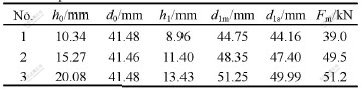
The disk compression tests were performed on 200 kN universal material testing machine in State Key Laboratory of Rolling and Automation NEU. The dimensions of three groups of disks before and after compression, and the indicator readings of the machine are listed in Table 1. The ram speed was 30 mm/min.
Table 1 Disk dimensions before and after compression and indicated pressure
Taking disk No.1 (Table 1) as an example, the calculating procedure is given in detail as

According to Eqns.(6) and (10), we obtain
 ξ=1.006 5, η=-2.019 1
Therefore
m=0.25.
Then substituting the data into Eqn.(9) leads to
nσ=1.19.
From the measured data, we have


According to the value of  and
and  , it can be checked out σs=21.10 MPa[13]. Then the total compre- ssion force can be obtained:

The error between the calculated and measured force in Table 1 is Δ=-1.28%.
With the same procedure, the calculated results for specimens 2 and 3 are listed in Table 2.
Table 2 Calculated results of three group disks
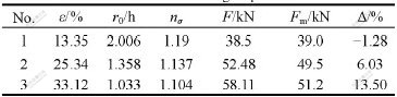
From Table 2 we can see that the calculated results for groups No.1 and 2 are basically in agreement with the measured ones, and that when the pass reduction is less than 25.34% the relative error between them is less than 6%. However, when the pass reduction is up to 33%, the error may reach 13.5%, exceeding engineering permissible error.
5 Discussion
Regarding Eqn.(9), AVITZUR’s approximate solution is[7, 8]
 (16)
(16)
By Eqn.(16) the calculated results for the three groups of disk are also obtained and listed in Table 3.
From Tables 2 and 3, it can be seen that the results by Eqn.(9) and Eqn.(16) are basically in agreement.
Let m=0.1-0.85 and r0/h=1, 2, 3, the calculated stress effective factors nσ by Eqns.(9) and (16) are compared in Fig.3.
Fig.3 shows that the value of stress effective factor, nσ, increases with increasing m value for the same
Table 3 Calculated results by Eqn.(16)
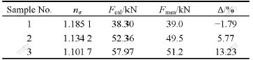

Fig.3 Comparison of stress effective factor by Eqns.(9) and (16)
geometry r0/h, but the results by Eqn.(9) are a little higher than those by Eqn.(16). For a given friction factor m, the nσ increases with increasing value of r0/h. This trend for disk forging is similar to the basic rule exploited by Slab method[14,15], Upper-bound and UPET[16], as well as FEM[3].
It should be pointed out that the stress effective factor of previous example can also be checked out immediately with the calculated curves by given m and r0/h, as illustrated in Fig.3.
6 Conclusions
1) When direction cosines are determined by the ratio of coordinate increments, the plastic power integrated by strain rate vector inner-product satisfies Eqn.(6), stress effective factor satisfies Eqn.(9), and nonlinear relation between bulge parameter b and friction factor m satisfies Eqn.(10).
2) With compression tests, the stress effective factors and total pressures are calculated by Eqns.(9) and (16), respectively. The calculated results are basically consistent. The stress effective factor nσ increases with increase in both friction factor m and geometric parameter r0/h.
3) When reduction in pass is less than 25%, the relative errors between calculated and measured total forces are less than 6%, and when reduction in pass gets up to 33.12%, the errors are more than 13%, which already exceeds engineering error limit of 10%.
References
[1] TARNOVSKII I Y. Theory of Metal Forming by Pressure [M]. Moscow: Metallurgizdat, 1963. 55-67. (in Russian)
[2] KOPP R. Some current development trends in metal-forming technology [J]. Journal of Materials Proceeding Technology, 1996, 60: 1-9.
[3] PITTMAN J F T. Numerical Analysis of Forming Processes [M]. New York: John Wiley and Sons, 1984. 32-33.
[4] YANG H, ZHAN M, LIU Y L, XIAN F J, SUN Z C, LIN Y, ZHANG X G. Some advanced plastic processing technologies and their numerical simulation [J]. Journal of Materials Processing Technology, 2004, 151: 63-69.
[5] ADEL A, JAY G S. An upper bound elemental technique approach to the process desigh axisymmetric forging by forward and backward simulation [J]. Journal of Materials Processing Technology, 2003, 142: 619-627.
[6] BARAYA G L, JOHNSON W. Advances in Machine Tool Design and Research [M]. New York: Pergamon Press, 1964. 449-455.
[7] AVITZUR B. Metal Forming: Processes and Analysis [M]. New York: McGRAW-HILL, Inc, 1968. 102-111.
[8] AVITZUR B. Metal Forming: The Application of Limit Analysis [M]. New York: McGRAW-HILL, Inc, 1980. 158-163.
[9] JUNEJA B L. Forging of polygonal discs [J]. Int J Mach. Tool Des Res, 1973, 13(1): 17-28.
[10] ZHAO De-wen. Mathematical Solutions of Continuum Forming Force [M]. Shenyang: Northeastern University Press, 2003. 421-425. (in Chinese)
[11] ZHAO De-wen, WANG Lei, LIU Xiang-hua, WANG G D. Solution for slab forging with bulge between two parallel by strain rate vector inner-product integration and series expansion [J]. Trans Nonferrous Met Soc China, 2005, 15(5): 1009-1013.
[12] ZHAO De-wen, WANG Lei, LIU Xiang-hua, WANG G D. Solution of strain vector analysis in forging of rectangular workpiece [J]. Journal of Plasticity Engineering, 2005, 12(2): 85-88. (in Chinese)
[13] LOIZOU N, SIMS R B. The yield stress of pure lead in compression [J]. Journal of the Mech and Phy Solids, 1953(1): 234-243.
[14] WILLIANM F H. Metal Forming Mechanics and Metallurgy [M]. Englewood Cliffs: Prentice-Hall Inc, 1983. 123-124.
[15] SLATER R A C. Engineering Plasticity Theory and Application to Metal Forming Processes [M]. London: The Macmillan Press Ltd, 1977: 266-269.
[16] WANG Zhen-fan. Upper Bound Solution and Its Application in Metal Forming [M]. Shenyang: Northeast University of Technology Press, 1991. 200-203. (in Chinese)
(Edited by LONG Huai-zhong)
Foundation item: Project(50474015) supported by the National Natural Science Foundation of China
Corresponding author: ZHAO De-wen; Tel: +86-24-83686423; E-mail: zhaodwmail@163.com

