
Flattening behavior of copper droplets in plasma spray forming
ZENG Hao-ping(曾好平)
School of Mechanical Engineering, University of Science and Technology Liaoning, Anshan 114051, China;
Received 15 July 2007; accepted 10 September 2007
Abstract: A two-dimensional axisymmetric model, with 8700 and 7500 quadrilateral elements for the fluid and substrate zone separately, was developed to simulate the impacting and flattening process. The volume of fluid technique was employed to track the interface between the air and droplet. The relationships between the droplet pre-impact parameters and the flattening time as well as the flattening ratio were investigated by altering one of the parameters while remaining the others unchanged. The results show that the droplet height reaches its minimum value at approximately half of the spreading time, which also indicates the finish of vertical fluid flow at that time. The flattening ratio increases with the increase of the three pre-impact parameters-droplet diameter, temperature and velocity, even though the flattening time decreases when the droplet velocity increase.
Key words: copper droplets; flattening behavior; simulation; plasma spray forming
1 Introduction
Plasma spray forming has found a wide range of applications in the manufacturing of molds and parts with good material versatility, low manufacturing cost and short cycle time of production[1-3]. However, the microstructure of the formed coating by this technology is significantly influenced by the droplet flattening behavior[4-5]. Hence, there has been increasing interest in the study of droplet transformation related to this process.
The droplet flattening process involved in thermal spraying has been studied intensively with experimental methods during the last decades[6-9]. Although the flattening process of the droplets in these experiments is similar to that in thermal spraying in both Reynolds and Weber numbers, they are different in undercooling degree, nucleation delay and thermal contact resistance.
To avoid the disadvantages of experimental methods, many numerical models have been built to simulate the splat formation under thermal spraying conditions. By modeling the spreading process of droplets impacting onto a flat cold substrate with finite-element methods, BERTAGNOLLI et al[10] have predicted the flattening ratios of ceramic droplets against Reynolds numbers and flattening time. FENG et al[11] have also developed a finite element model to simulate the flattening deformation of aluminum droplets impacting onto a substrate with different surface roughness. In contrast to the two-dimensional models mentioned above, PASANDIDEH-FARD et al[12-13] have built three-dimensional models to imitate the flattening and solidification process of alumina and tin droplets on different substrate conditions. However, in these systems, either the heat conducting effects of the substrate have been rarely considered or the substrate temperature has been assumed to be fixed at a constant value.
In this paper the flattening simulation of copper droplets of typical geometric dimensions in plasma spray forming on a flat and smooth stainless steel substrate was presented with the help of fluent. The influence of droplet pre-impact parameters on the flattening time and ratio was further investigated. The heat conduction effects of the substrate were taken into account by designating the initial temperature and heat boundary conditions of the substrate.
2 Mathematical model
During the flattening transformation in this project, the isothermal copper droplets were assumed to impact onto the stainless steel substrate vertically in a completely molten state, and the liquid of the droplets was regarded as incompressible and laminar fluid. As for the substrate, it was supposed to be a flat, rigid and smooth surface as in most studies. The heat transferred from the droplets to the environment by radiation was considered to be negligible compared with the heat conducted to the substrate.
The dynamics of the droplet liquid and surrounding air is governed by the following equations.
Continuity equation:
 (1)
(1)
Momentum equation (Navier-Stokes equation)
 (2)
(2)
Energy equation:
 (3)
(3)
where u is the velocity vector, f is the body force vector and τ is the stress tensor; t, ρ, p, μ, e, q, are time, density, pressure, kinematic viscosity, internal energy and heat flux respectively. The volume of fluid (VOF) [14] technique is applied to track the free surface of the flattening droplet.
The computational domain as shown in Fig.1 is the two-dimensional axisymmetric model constructed in this study, which is composed of 8700 and 7500 quadrilateral elements for the fluid and substrate zone separately. The mesh is biased for the interface and symmetric axis where impacting, flattening and solidification occur. No-slip and no-penetration conditions are assumed at the liquid-solid interface, and the thermal contact resistance is assumed to be 5×10⁻⁷ m2?K?W-1. The rest of the fluid domain peripheries are set to be zero pressure outlets.
The physical properties of copper and stainless steel are listed in Table 1.
3 Results and discussion
The flattening and spreading process of a 30 μm copper droplet, impacting onto the substrate initially preheated to 400 K at velocity of 100 m/s and temperature of 1 450 K, is shown in Fig.2.
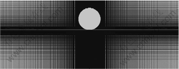
Fig.1 Schematic diagram of mesh of droplet and substrate
Table 1 Physical properties of copper and stainless steel[15-17]
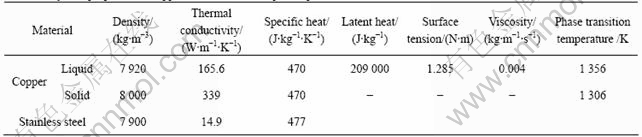

Fig.2 Simulated flattening process of copper droplet: D=30 μm, v=100 m/s, T=1 450 K, Tsub=400 K
It can be seen that the droplet spreads quickly along the radial direction immediately after impacting onto the substrate. As the fluid flows radially, the height of the droplet decreases sharply-especially at the initial stage, as is demonstrated more clearly in Fig.3. The height of the droplet reduces to around 13 μm at 0.2 μs, which is only 43% of its original value. At 0.4 μs, the droplet height further diminishes to 4.8 μm, with only 16% of the initial height left. The splat reaches its minimum height of 1.8 μm at 0.75 μs, which also indicates the finish of vertical fluid flow. The flattened droplet reaches its maximum diameter of 134 μm at approximately 1.4 μs, which is approximately twice of the time that the droplet finishes vertical fluid flow. Thereafter, the splat recoils back to 127 μm under the effect of surface tension at 3.8 μs, which implies a final flattening ratio of 4.2.
To investigate the influence of the droplet pre-impact parameters on the flattening behavior, the
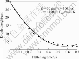
Fig.3 Change of droplet height against flattening time
flattening time and ratios are predicted at variant diameters, velocities and temperatures by simulation. Fig.4 shows the developing tendency of flattening time and ratios against the droplet diameters. When the droplet diameter increases from 30 to 55 μm, the flattening time extends from 1.4 to 2.5 μs, and the flattening ratio increases from 4.2 to 4.97 simultaneously. The reason for this change is that the effect of solidification on the fluid flow is comparatively weakened when the droplet diameter increases, which enables the liquid to spread more completely.
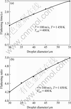
Fig.4 Influences of droplet diameter on flattening time(a) and flattening ratio(b)
Fig.5 demonstrates the influence of droplet temperatures on the flattening time and ratios. It can be seen that the rise in droplet temperature is accompanied by a similar change in flattening time and ratios. When the droplet temperature increases up from 1 450 to 1 650 K, the flattening time increases from 1.4 to 1.9 μs, and the flattening ratio changes from 4.2 to 4.9. When the droplet temperature increases, more heat will need to be transferred from the fluid to the substrate and the surrounding air before the droplet solidifies, and this will lengthen the time that the fluid flows.
Fig.6 describes the influence of droplet velocities on the flattening time and ratios. In contrast to the positive correlation between the flattening time and droplet
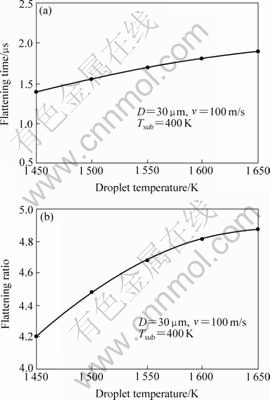
Fig.5 Influences of droplet temperature on flattening time(a) and flattening ratio(b)
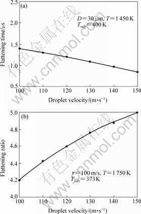
Fig.6 Influences of droplet velocity on flattening time(a) and flattening ratio(b)
diameters as well as temperatures, the relationship between the flattening time and droplet velocity is negative correlation. An increase of droplet velocity from 100 to 150 m/s shortens the flattening time from 1.4 to 0.9 μs, while a rise of the flattening ratio from 4.2 to 5.03 is still observed. In one hand, higher droplet velocity will accelerate the fluid flow, which shortens the flattening time consequently. On the other hand, higher droplet velocity implies more inertia energy to counteract the viscous resistance during the droplet spreading, yielding the result of higher flattening ratio.
Based on the simulation conducted above, the flattening ratio of the droplet can be enhanced by increasing its diameter, temperature and velocity. To the coating fabricated by plasma spray forming, higher flattening ratio of droplets usually implies relatively denser microstructure, better intensity and longer service time. Consequently, larger diameter, higher temperature and velocity are beneficial for the improvement of the product quality. However, one point to remember is that the droplet velocity is generally inversely proportional to its diameter. It is therefore necessary to balance between the control of the droplet diameter and its velocity.
4 Conclusions
1) The flattening behavior of copper droplets associated with plasma spraying is studied with a two-dimensional axisymmetric fluid dynamic model. The simulation reveals that the vertical fluid flow of the droplet finishes at approximately half of the flattening time when the droplet reaches its maximum diameter.
2) The increase of droplet diameter and temperature prolongs the droplet flattening time, and the flattening ratio also increases as a result. The increase of droplet velocity similarly augments the splat flattening ratio, even though the flattening time is shortened. The increases of the droplet diameter, temperature and velocity are favorable for the quality improvement of the coatings in microstructure, intensity and service time.
References
[1] FANG Jian-cheng, XU Wen-ji. Plasma spray forming[J]. Journal of Materials Processing Technology, 2002, 129: 288-293.
[2] GEIBEL A, FROYEN L, DELAEY L. Plasma spray forming: An alternate route for manufacturing free-standing components[J]. Journal of Thermal Spray Technology, 1996, 5: 419-429.
[3] Fang J C, Xu W J, Zhao Z Y, Wang L. FGM mould with fine veins rapidly manufactured by plasma spraying[J]. Key Engineering Materials, 2005, 291/292: 609-614.
[4] MOSTAGHIMI J, PASANDIDEH-FARD M, CHANDRA S. Dynamics of splat formation in plasma spray coating process[J]. Plasma Chemistry and Plasma Processing, 2002, 22(1): 59-84.
[5] FANG Jian-cheng, XU Wen-ji, ZHAO Zi-yi. Arc spray forming[J]. Journal of Materials Processing Technology, 2005, 164/165: 1032-1037.
[6] MASAHIRO F, EIJI N, TOSHIKAZU M. Flattening and solidification behavior of a metal droplet on a flat substrate surface held at various temperatures[J]. Surface and Coatings Technology, 1999, 120/121: 131-137.
[7] MASAHIRO F, EIJI N, TOSHIKAZU M. Effect of interface wetting on flattening of freely fallen metal droplet onto flat substrate surface[J]. Journal of Thermal Spray Technology, 2002, 11(1): 69-74.
[8] SHAKERI S, CHANDRA S. Splashing of molten tin droplets on a rough steel surface[J]. International Journal of Heat and Mass Transfer, 2002, 45: 4561-4575.
[9] AMADA S, TOMOYASU K, HARUYAMA M. Splat formation of molten Sn, Cu and Ni droplets[J]. Surface and Coatings Technology, 1997, 96: 176-183.
[10] BERTAGNOLLI M, MARCHESE M, JACCUCI G. Modeling of particles impacting on a rigid substrate under plasma spraying conditions[J]. Journal of Thermal Spray Technology, 1995, 4(1): 41-49.
[11] FENG Z G, DOMASZEWSKI M, MONTAVON G, CODDET C. Finite element analysis of effect of substrate surface roughness on liquid droplet impact and flattening process[J]. Journal of Thermal Spray Technology, 2002, 11(1): 62-68.
[12] PASANDIDEH-FARD M, MOSTAGHIMI J. On the spreading and solidification of molten particles in a plasma spray process: effect of the thermal contact resistance[J]. Plasma Chemistry and Plasma Processing, 1996, 16(1): 83S-98S.
[13] PASANDIDEH-FARD M, BHOLA R, CHANDRA S, MOSTAGHIMI J. Deposition of tin droplets on a steel plate: simulations and experiments[J]. International Journal of Heat and Mass Transfer, 1998, 41: 2929-2945.
[14] HIRT C W, NICHOLS B D. Volume of fluid(VOF) method for the dynamics of free boundaries[J]. Journal of Computational Physics, 1981, 39: 201-225.
[15] AMADA S, OHYAGI T, HARUYAMA M. Evaluation of splat profile for droplet impingement[J]. Surface and Coatings Technology, 1999, 115: 184-192.
[16] BOUCHARD D, HOWES B, PAUMELLE C, NADEAU J P SIMARD D, FRANC-HAMEL O G. Control of heat transfer and growth uniformity of solidifying copper shells through substrate temperature[J]. Metall Mater Trans B, 2002, 33(3): 403-411.
[17] KAMNIS S, GU S. Numerical modelling of droplet impingement[J]. Journal of Physics D: Applied Physics, 2005, 38: 3664-3673.
(Edited by LONG Huai-zhong)
Foundation item: Project (50675072) supported by the National Natural Science Foundation of China; Project (E0610018) supported by the Natural Science Foundation of Fujian Province, China; Project (20062178) supported by the Natural Science Foundation of Liaoning Province, China
Corresponding author: ZENG Hao-ping; Tel: +86-13889770938; E-mail: zenghaoping@sohu.com

