搅拌铸造工艺参数对AA6061/TiC铝基复合材料抗拉强度影响的预测
来源期刊:中国有色金属学报(英文版)2016年第6期
论文作者:J. JEBEEN MOSES I. DINAHARAN S. JOSEPH SEKHAR
文章页码:1498 - 1511
关键词:铝基复合材料;搅拌铸造;TiC;抗拉强度
Key words:aluminum matrix composite; stir casting; TiC; tensile strength
摘 要:采用搅拌铸造工艺制备AA6061/15%TiC (质量分数)铝基复合材料。构建一个经验公式用于预测搅拌铸造工艺参数对AA6061/TiC铝基复合材料极限抗拉强度的影响。采用有4因素、5水平组成的中心旋转组合设计方案来减少搅拌铸造实验次数。实验因素包括搅拌速率、搅拌时间、搅拌叶片角度和铸造温度。采用所建立的经验公式和显微组织观察分析这些因素对AA6061/TiC铝基复合材料极限抗拉强度的影响。分析结果表明:上述各因素均显著影响复合材料的极限抗拉强度。复合材料极限抗拉强度的变化归因于孔隙率、团簇的形成、TiC颗粒在晶界的偏析及其在铝基体中的均匀分布。
Abstract: Stir casting was used to produce AA6061/15%TiC (mass fraction) aluminum matrix composites (AMCs). An empirical relationship was developed to predict the effect of stir casting parameters on the ultimate tensile strength (UTS) of AA6061/TiC AMCs. A central composite rotatable design consisting of four factors and five levels was used to minimize the number of experiments, i.e., castings. The factors considered were stirring speed, stirring time, blade angle and casting temperature. The effect of those factors on the UTS of AA6061/TiC AMCs was derived using the developed empirical relationship and elucidated using microstructural characterization. Each factor significantly influenced the UTS. The variation in the UTS was attributed to porosity content, cluster formation, segregation of TiC particles at the grain boundaries and homogenous distribution in the aluminum matrix.
Trans. Nonferrous Met. Soc. China 26(2016) 1498-1511
J. JEBEEN MOSES1, I. DINAHARAN2, S. JOSEPH SEKHAR1
1. Department of Mechanical Engineering, St. Xavier’s Catholic College of Engineering, Nagercoil 629003, Tamil Nadu, India;
2. Department of Mechanical Engineering Science, University of Johannesburg, Auckland Park Kingsway Campus, Johannesburg 2006, South Africa
Received 2 July 2015; accepted 12 August 2015
Abstract: Stir casting was used to produce AA6061/15%TiC (mass fraction) aluminum matrix composites (AMCs). An empirical relationship was developed to predict the effect of stir casting parameters on the ultimate tensile strength (UTS) of AA6061/TiC AMCs. A central composite rotatable design consisting of four factors and five levels was used to minimize the number of experiments, i.e., castings. The factors considered were stirring speed, stirring time, blade angle and casting temperature. The effect of those factors on the UTS of AA6061/TiC AMCs was derived using the developed empirical relationship and elucidated using microstructural characterization. Each factor significantly influenced the UTS. The variation in the UTS was attributed to porosity content, cluster formation, segregation of TiC particles at the grain boundaries and homogenous distribution in the aluminum matrix.
Key words: aluminum matrix composite; stir casting; TiC; tensile strength
1 Introduction
Aluminum alloys reinforced with various particulates, universally called as aluminum matrix composites (AMCs) have been the subject of many researches in the past two decades owing to their superior properties. Conventional monolithic aluminum alloys fail to meet the rising demand for high performance in many applications. AMCs have the right combination of properties such as higher stiffness, superior strength, improved resistance to wear and low coefficient of thermal expansion, which promote them as a potential alternative material to replace aluminum alloys. The utilization of AMCs exhibits an increasing trend in various industries including aerospace, automotive, marine and nuclear [1-4]. A range of carbide, oxide, boride and nitride particles have been used as particulate reinforcements to produce AMCs. Among them, TiC is an interesting ceramic particulate which possesses high hardness and elastic modulus, low density, good wettability with molten aluminum and low chemical reactivity. The introduction of TiC particles into the aluminum matrix significantly improves the high temperature properties. In addition, TiC particle is a grain refiner and provides nucleation sites during solidification of AMCs [5-9].
Stir casting is the most commonly used method for the production of AMCs compared with other methods. The aluminum alloy is melted completely in an electrical furnace attached with an impeller or a stirrer. The furnace is usually provided with an inert gas atmosphere to avoid contamination. The stirrer is switched on and the aluminum melt is stirred to form a vortex. The ceramic particles are fed at a constant rate at the periphery of the vortex. The ceramic particles mix with the molten aluminum to form an aluminum composite melt. After sufficient amount of stirring, the aluminum composite melt is poured into a mould for solidification [10,11]. Stir casting is an economical method to produce AMCs and suitable for mass production. It is also simple and yields near net shape components. Products having many features and irregular contours can be made using stir casting [12]. Hitherto, stir casting has been effectively applied to producing AMCs reinforced with SiC [13], Al2O3 [14], TiC [15], B4C [16], SiO2 [17], AlN [18], Si3N4 [19], TiB2 [20], WC [21], fly ash [22] particulates and CNT [23]. The selection of process parameters is crucial to obtain sound AMCs because stir cast AMCs are susceptible to micro porosity, poor distribution, interfacial reaction and decomposition of ceramic particles [24,25].
A large number of literatures are available on the production of AMCs using stir casting. Nevertheless, the effect of process parameters is reported in limited number of literatures [26-37]. NAI and GUPTA [26] found an increase in the homogeneity of particle distribution with an increase in stirring speed in AA1050/SiC AMCs. NAHER et al [27] simulated the influence of stirring speed, stirring time and blade angle using water/glycerol solutions. AKHLAGHI et al [28] studied the effect of casting temperature on particle distribution and porosity of A356/SiC AMCs. PRABU et al [29] noticed poor particle distribution and clustering at lower stirring speeds and less stirring time in A384/SiC AMCs. RAVI et al [30] investigated the effect of stir casting variables through a water based model. AMIRKHANLOU and NIROUMAND [31] obtained improved distribution of the reinforcement particles and properties at lower casting temperatures in A356/SiCp AMCs. ZHANG et al [32] investigated the influence of stirring speed, stirring time and casting temperature on the microstructure of Al-6.8Mg/SiC AMCs. GUAN et al [33] detected an increase in the homogeneity of reinforcement and tensile properties with decreasing the stirring temperature and increasing the stirring time in AA6061/(ABOw+SiCp) hybrid AMCs. SAJJADI et al [34] showed that lower casting temperature provided proper distribution and good mechanical properties in A356/ Al2O3 AMCs. DU et al [35] established an empirical relationship between the stirring speed and radial distribution of particles in A356/SiCp AMCs. AKBARI et al [36] observed an increased porosity content with an increase in stirring time in A356/Al2O3 AMCs. KHOSRAVI et al [37] reported an increase in the porosity content with an increase in stirring speed and casting temperature in A356/SiCp AMCs.
Most of the published literatures concentrated on the effect of few process parameters with limited number of experiments. The process parameters were chosen randomly and their effects were studied based on microscopic observation. No numerical or empirical relationships were developed to predict the properties over a wide range of process parameters. Therefore, the objective of the present work is to produce AA6061/TiC AMCs using stir casting and develop an empirical relationship incorporating the stir casting variables to predict the tensile strength. The effect of stir casting variables on the tensile strength is deduced from the developed empirical relationship and correlated with the observed microstructure. The experiments, i.e., castings were carried out according to the central composite design (CCD) adopting statistical approach. Several investigators effectively applied CCD for various manufacturing processes to precisely predict the influence of process parameters on the responses [38-42].
2 Experimental
2.1 Identification of process parameters
The stir casting parameters which influence the microstructure and mechanical properties of AMCs are shown in Fig. 1. The key parameters which appreciably influence the properties of AMCs are stirring speed (S), stirring time (t), blade angle (A) and casting temperature (T). These parameters were chosen for the present study based on literature survey [26-37].
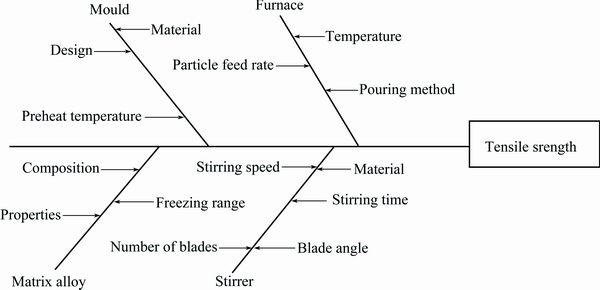
Fig. 1 Stir casting parameters influencing tensile strength of AMCs
2.2 Limits of process parameters
The limits of each factor were decided based on trial castings to avoid macro porosity, settling of TiC particles at the bottom of the crucible, decomposition of TiC particles and abnormal stirring, i.e., splash. The upper and lower limits of a factor were coded as +2 and -2 respectively for the convenience of recording and processing experimental data. The intermediate values were calculated from the following relationship:
Xi =2[2X-(Xmax+Xmin)]/(Xmax-Xmin) (1)
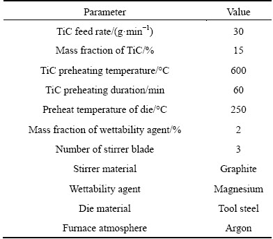
where Xi is the required coded value of variable X; X is any value of the variable from Xmin to Xmax; Xmin is the lowest level of the variable; Xmax is the highest level of the variable. The chosen levels and selected process parameters with their units and notations are presented in Table 1. Other casting parameters maintaining constant values are shown in Table 2.
Table 1 Stir casting parameters and their levels
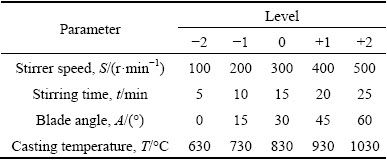
Table 2 Constant stir casting parameters and their values
2.3 Development of design matrix
A four-factor, five-level central composite rotatable factorial design consisting of 31 sets of coded conditions with seven center points as-presented in Table 3 was selected to carry out the experiments. A comprehensive account of the design matrix is available elsewhere [43,44].
Table 3 Design matrix with its experimental results

2.4 Casting of AMCs according to design matrix
Aluminum alloy AA6061 was used as matrix material in this work. Measured quantity of AA6061 rods were placed inside the furnace. The chemical composition of AA6061 aluminum alloy is presented in Table 4. The stir casting facility (M/s Swamequip, Chennai, India) and the die used to produce AA6061/TiC AMCs are respectively shown in Figs. 2 and 3. It is an electrical resistance furnace attached with a bottom pouring arrangement. Hence, after solidification, the top and bottom of the casting will fairly represent the corresponding distribution at the top and bottom of the crucible prior to pouring. The bottom pouring method drastically reduces the time to transfer the composite melt to the mould and avoids the change in distribution of particles [15]. The mechanical stirrer was positioned into the aluminum melt at 2/3 of the total height of aluminum melt. Figure 4 shows the fabricated graphite mechanical stirrer. TiC particles were gradually fed into periphery of the vortex using a feeding mechanism. The morphologies of the TiC particles are depicted in Fig. 5. The average size of TiC particles was 2 μm. HASHIM et al [24] reported that particles with size less than 10 μm will suspend in the aluminum melt for a long time influenced by gravity. TiC particles were preheated to improve wettability in addition to magnesium incorporation into the aluminum melt. The furnace was provided with an argon-rich atmosphere to prevent aluminum oxide formation. The composite melt was then poured into a preheated die. Castings were taken by changing the process parameters as per the experimental design. Figure 6 represents a batch of AA6061/TiC AMC castings.
Table 4 Chemical composition of AA6061 aluminum alloy (mass fraction, %)
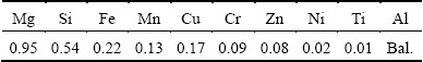

Fig. 2 Stir casting facility
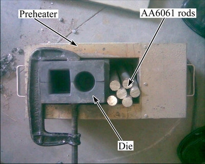
Fig. 3 Permanent mould and preheater
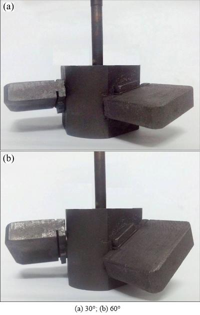
Fig. 4 Photographs of fabricated graphite stirrer blades with different blade angles
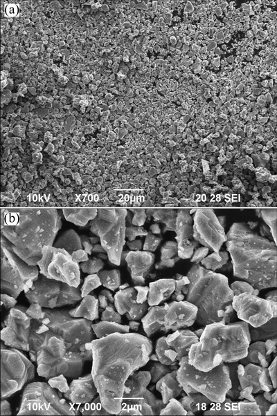
Fig. 5 SEM images of TiC powders at lower (a) and higher (b) magnifications
2.5 Recording response
Tensile specimens were prepared as per ASTM E8M standard having a gauge length, width and thickness of 40, 7 and 6 mm, respectively. Six tensile specimens were prepared from each casting from various locations. Figure 7 corresponds to a batch of tensile specimens. The mean value of each set of six specimens was taken into account (Table 3) for developing an empirical relationship. The ultimate tensile strength (UTS, σ) was estimated using a computerized universal testing machine.

Fig. 6 Batch of AA6061/TiC AMC castings
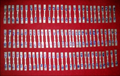
Fig. 7 Batch of prepared tensile specimens
2.6 Development of empirical relationship
The response functions representing the UTS of AA6061/TiC AMCs are functions of stirring speed (S), stirring time (t), blade angle (A) and casting temperature (T) which can be expressed as
σ=f(S, T, A, T) (2)
The second order polynomial regression equation used to represent the response “Y” for k factors is given by
 (3)
(3)
The selected polynomial for four factors could be expressed for the response as
σ=b0+b1S+b2t+b3A+b4T+b11S 2+b22t2+b33A2+b44T2+b12St+b13SA+b14ST+b23tA+b24tT+b34AT (4)
where b0 is the average of responses and b1, b2, …, b4, b11, b22, …, b44 are the response coefficients that depend on respective main and interaction effects of parameters. The coefficients were calculated using the software SYSTAT 12. The empirical relationship was developed after determining the coefficients. All the coefficients were tested for their significance level at 95% confidence level. The insignificant coefficients were eliminated without affecting the accuracy of the empirical relationships using student t-test. The significant coefficients were taken into account to construct the final empirical relationship. The final developed empirical relationship with processing factors in coded form is given below:
σ=233.286+0.167S-0.667t+1.5A+1.833T-15.217S2-12.342t2-12.967A2-8.842T2 (5)
2.7 Adequacy of empirical relationships
The statistical results of the developed empirical relationship are presented in Table 5. The predicted empirical relationship values will precisely match with the experimental results if the R2 value is 1. Higher values of R2 and lower values of standard error (SE) indicate that the empirical relationship is adequate. The adequacy of the developed empirical relationship was analyzed using analysis of variance (ANOVA) technique which is presented in Table 6. The calculated F ratios are higher than the tabulated values at 95% confidence level. Hence, the developed empirical relationship is adequate. Further, the scatter diagram as presented in Fig. 8 shows that the actual and predicted values are scattered both sides and close to 45° line, which confirm the adequacy of the empirical relationship.
Table 5 Statistical results of developed empirical relationship

2.8 Microstructural characterization
Specimens were prepared from selected castings. They were polished using standard metallographic technique and etched with Keller’s reagent. The etched specimens were observed using scanning electron microscope (SEM, JEOL-JSM-6390) and field emission scanning electron microscope (FESEM, CARL ZEISS- Sigma HV).
Table 6 ANOVA results of developed empirical relationship

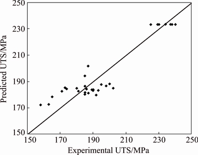
Fig. 8 Scatter diagram of developed model
3 Results and discussion
The effects of process parameters such as stirring speed, stirring time, blade angle and casting temperature on the UTS (σ) of AA6061/TiC AMCs were deduced from the developed empirical relationship. The effects of process parameters on the UTS of AA6061/TiC AMCs and the possible causes are expounded in the following sections. It is desirable to achieve homogenous distribution to obtain higher tensile strength.
3.1 Effect of stirring speed
The predicted effect of stirring speed on the UTS of AA6061/TiC AMCs is shown in Fig. 9 at a constant stirring time of 15 min, blade angle of 30° and casting temperature of 800 °C. The UTS increases as stirring speed increases and reaches the maximum at 300 r/min. Further increase in stirring speed leads to the reduction of UTS.
The rotation of the stirrer creates a vortex within the aluminum melt as well as disperses the fed particles into the aluminum melt by setting up centrifugal currents. A vortex formation is essential to incorporate the reinforcement particles. The size of vortex formed limits the degree of particle mixing and its dispersion into the melt. The magnitude of the circulating currents generated during the stirring should be strong enough to keep the particles in suspension for longer duration. The stirring speed influences both the size of vortex and the magnitude of the circulating current linearly. A deep vortex and high stirring speed result in turbulence and suction of air bubbles. This is an undesirable situation and leads to gas entrapment. The study of micrographs aids to correlate the effect of stirring speed on tensile behavior.
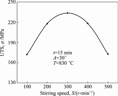
Fig. 9 Effect of stirring speed on UTS (σ) of AA6061/TiC AMCs
Figure 10 shows representative micrographs of AA6061/TiC AMCs at various stirring speeds. It is evident from these micrographs that the stirring speed influences the distribution of TiC particles and the formation of porosity. The distribution is poor and hetrogeneous at lower stirrer speed of 100 r/min (Fig. 10(a)). Some regions do not have the dispersion of TiC particles which are known as particle-free regions. Clusters of TiC particles are observed in some other regions. The micrograph is a mixture of particle-free regions, clusters and fairly distributed regions. The stirring speed is insufficient to disperse the particles sufficiently into the melt. The micrograph at a stirring speed of 300 r/min (Fig. 10(b)) depicts a finer distribution of TiC particles. The increase in stirring speed increases the centrifugal current within the aluminum melt which in turn disintegrates the TiC clusters into homogenously distributed particles. The vortex created is an optimum one to achieve homogenous distribution. The micrograph at a stirring speed of 500 r/min (Fig. 10(c)) shows further improved distribution of TiC particles in the aluminum matrix. The increase in stirring speed from 100 to 500 r/min increases the average interparticle distance. But regions of porosity are found in the micrograph. The porosities observed in stir cast AMCs are of four types; 1) porosity associated with individual particle; 2) porosity associated with particle clusters; 3) micro porosity in the aluminum matrix; 4) gas porosity [26]. The shape of the porosity is observed to be spherical in nature which confirms gas porosity. The vortex formed at a stirring speed of 500 r/min is vigorous and sucks atmosphere air into the aluminum melt due to higher pressure difference. The height of the vortex nearly reaches the stirrer blade. This result agrees to the findings of RAVI et al [30]. The gas porosities are not observed at stirring speeds of 100 and 300 r/min for the constant cooling rate. The amount of gas sucked is more at 500 r/min which does not relieve completely during solidification. The entrapped gases form gas porosity in the AMC casting.
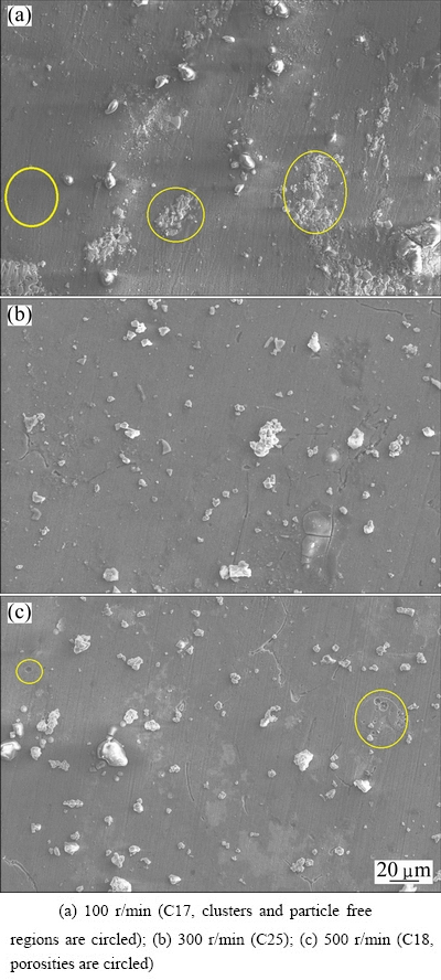
Fig. 10 FESEM images of AA6061/TiC AMCs at different stirring speeds
3.2 Effect of stirring time
The predicted effect of stirring time on the UTS of AA6061/TiC AMCs is depicted in Fig. 11 at a constant stirring speed of 300 r/min, a blade angle of 30° and a casting temperature of 830 °C. The UTS increases as stirring time increases and reaches maximum at 15 min. Further increase in stirring time leads to the reduction of UTS.
The creation of vortex by the stirrer rotation draws the particles into the aluminum melt. The fed particles will not disperse into all regions of the aluminum melt at once. The dispersion is a function of time [29]. The particles need to be subjected to constant centrifugal currents over a definite period of time to achieve dispersion all through the aluminum melt. Conversely, the vortex has the tendency to suck the air into the aluminum melt. The amount of air sucked depends on the stirring time. A longer stirring time will lead to excessive air entrapment resulting in porosity in the casting. The observation of micrographs of AA6061/TiC AMC casting at various stirring time reveals the effect of stirring time.
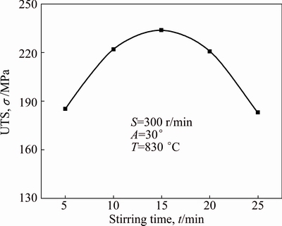
Fig. 11 Effect of stirring time on UTS (σ) of AA6061/TiC AMCs
Figure 12 depicts representative micrographs of AA6061/TiC AMCs at various stirring time. The variations in the micrographs clearly indicate the effect of stirring time. The micrograph (Fig. 12(a)) at a stirring time of 5 min presents a large number of clusters. Particle-free regions are also observed. The microstructure is highly heterogeneous. A stirring time of 5 min is insufficient to disperse the TiC particles throughout the aluminum matrix. TiC particles remain closer to each other in the aluminum melt which form clusters. The micrograph (Fig. 12(b)) at a stirring time of 15 min shows a homogenous distribution of TiC particles in the aluminum matrix. No clusters are visible. The average interparticle distance increases. The increase in stirring time produces finer distribution of particles. As the stirring time increases, the centrifugal currents within the molten aluminum collapse the clusters. The particles in the clusters are driven away to particle-free regions. As a result, the distribution is improved over stirring time. The micrograph (Fig. 12(c)) at a stirring time of 25 min depicts improved distribution of TiC particles at the cost of porosity. The increase in stirring speed further (15 min) improves the distribution to some extent. But various types of porosities as discussed earlier in Section 3.1 are noticed. The formation of porosity in the cast AMCs is influenced by a number of parameters such as gas entrapment during stirring, air bubbles entering the composite melt, water vapor on the surface of the ceramic particles, hydrogen evolution and solidification shrinkage. Longer stirring time produces more agitation in the molten composite which increases the tendency to form more porosity [36]. Hence, a longer stirring time is detrimental to the desired microstructure. The obtained results indicate that there is an optimum range of stirring time to achieve uniform distribution with least porosity. If stirring continues beyond the optimum range, the gas absorbability of the molten aluminum will increase. Thus, the formation of porosity becomes unavoidable. The preferential nucleation and growth of gas bubbles during solidification lead to various kinds of porosities.
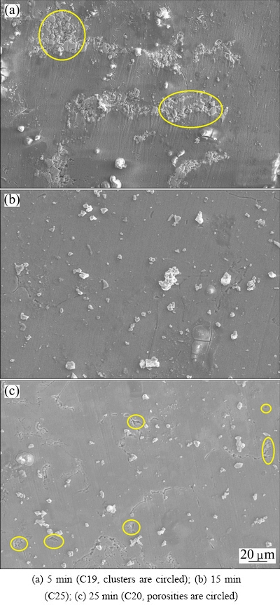
Fig. 12 FESEM images of AA6061/TiC AMCs at different stirring time
3.3 Effect of blade angle
The predicted effect of blade angle on the UTS of AA6061/TiC AMCs is depicted in Fig. 13 at a constant stirring speed of 300 r/min, a stirring time of 15 min and a casting temperature of 830 °C. The UTS increases as blade angle increases and reaches maximum at 30°. Further increase in blade angle leads to the reduction of UTS.
The currents generated by the stirrer rotation determine the distribution of particles within the melt. The axial and radial variation of the currents should be within a shorter range to achieve homogeneous distribution of particles. Previous studied indicated that an optimum inclination of the stirrer blade is required to disperse the particles uniformly into the melt [27,30,45,46]. A vertical stirrer blade resulted in the sedimentation of particles near the wall and bottom of the crucible. The stirrer blade angle refers to the inclination of the blade with respect to the horizontal plane which is perpendicular to the axis of the crucible. The blade angle directly influences the angular flow, i.e., velocity of the melt, and causes a variation in the axial and radial currents. The details of the micrographs at various blade angles will help to understand the effect of blade of angle.

Fig. 13 Effect of blade angle on UTS (σ) of AA6061/TiC AMCs
Figure 14 shows representative micrographs of AA6061/TiC AMCs at various blade angles. The micrographs are not alike, which gives confirmation to the effect of blade angle. The micrograph (Fig. 14(a)) at a blade angle of 0° presents many clusters of TiC particles as well as particle-free regions. TiC particles are grouped in selected regions and other regions are left unreinforced. The vortex developed at a blade angle of 0° is shallow but sufficient for particle incorporation. The rate of particle mixing is slow. The angular velocity of the aluminum melt is relatively low to induce currents of required magnitude. The low centrifugal currents lead to poor distribution and formation of clusters. The micrograph reveals that a flat and horizontal blade does not produce desired distribution. The micrograph (Fig. 14(b)) at a blade angle of 30° depicts a homogenous distribution of TiC particles in the aluminum matrix. The clusters of TiC particles are not seen. The result indicates that tilting the stirrer blade from the horizontal position yields good distribution. The increase in blade angle increases the angular velocity of the aluminum melt and improves the centrifugal currents within the melt. The higher currents aid to break up the clusters in the aluminum melt and result in homogenous distribution. Thus, the dispersion rate increases with increasing the blade angle. Figures 14(c) and (d) respectively describe the micrographs observed at the top and the bottom of the casting at a blade angle of 60°. The distribution of TiC particles across the depth of the casting from top to bottom is not constant. Hardly few TiC particles are observed (Fig. 14(c)) at the top of the casting. On the other hand, TiC particles are distributed homogenously at the bottom of the casting. But the distribution is stratified. The interparticle distance is too short at the bottom compared with the micrograph (Fig. 14(b)) at a blade angle of 30°. This indicates that more TiC particles are pushed towards the bottom of the crucible. The angular velocity is too high at a blade angle of 60°, leading to huge axial variation of the current. The molten aluminum above and below the stirrer undergoes differential centrifugal currents. Similar observations were reported in the literatures by NAHER et al [27] and RAVI et al [30]. The flow of aluminum melt becomes analogous to an intense swirl, dragging the TiC particles towards the bottom. Porosities are also noticed in the micrographs in Figs. 14(b) and (c). The swirl motion draws more air into the aluminum melt which is not relieved during solidification. The air entrapment leads to internal micro voids known as porosity. The blade angle of 30° is an optimum one to obtain the desired distribution.

Fig. 14 FESEM (a, b) and SEM (c, d) images of AA6061/TiC AMCs at different blade angles
3.4 Effect of casting temperature
The predicted effect of casting temperature on the UTS of AA6061/TiC AMCs is depicted in Fig. 15 at a constant stirring speed of 300 r/min, a stirring time of 15 min and a blade angle of 30°. The UTS increases as casting temperature increases and reaches the maximum at 830 °C. Further increase in casting temperature leads to the reduction of UTS.

Fig. 15 Effect of casting temperature on UTS (σ) of AA6061/ TiC AMCs
The casting temperature exerts its influence in number of ways including viscosity of the molten aluminum, gas absorbability, cooling rate of the casting and reactivity between reinforcement particle and the aluminum [28,47,48]. The viscosity of the molten aluminum is directly proportional to the casting temperature. The change in viscosity results in the following aspects. At lower viscosities, it is difficult to stir the aluminum properly. Particle movement within the molten aluminum, particularly vertical motion towards the bottom of the crucible known as settling, depends on the viscosity. If the viscosity is high, the movement of particle within the aluminum melt will be high and it will be difficult to secure homogeneous distribution. The increase in casting temperature increases the risk of higher gas absorption. The cooling rate is inversionally proportional to the casting temperature. Higher cooling rate produces reasonable distribution of particles and porosity. The chances of interfacial reaction are more at very high casting temperatures. In the light of these effects, the micrographs at various casting temperatures are discussed subsequently.

Fig. 16 SEM (a, c) and FESEM (b) images of AA6061/ TiC AMCs at different casting temperatures
Figure 16 shows representative micrographs of AA6061/TiC AMCs at various casting temperatures. The micrograph (Fig. 16(a)) at a casting temperature of 630 °C shows regions of TiC clusters. Few porosities are also observed. The binary phase equilibrium diagram of aluminum alloy AA6061 is given in Fig. 17(a) [49,50]. The magnesium and silicon in this aluminum alloy combines to form Mg2Si. The amount of Mg2Si was calculated using the chemical composition provided in Table 4 and was estimated to be 1.49% (mass fraction). The mass fraction of Mg2Si of the AA6061 used in this work is marked as a vertical line in Fig. 17(a). The liquidus and solidus temperatures were estimated to be 655 °C and 595 °C, respectively. The alloy remains in a semi-solid state within this region. Stir casting at semi-solid state is called as compo-casting or slurry casting or rheocasting [34,51,52]. There are contrary trends published by different investigators on compo- casting. Some reported the improved distribution and lower porosity [32,34,53] and vice versa [28,33]. The liquid fraction of the aluminum alloy within the freezing range was computed using Lever rule from Fig. 17(a) and presented in Fig. 17(b). The liquid fraction at the casting temperature of 630 °C is 20%. Yet, it was possible to stir the semi-solid slurry with difficulty and incorporate the particles. The distribution of TiC particles is related to the friction of the semi-solid slurry which depends upon the viscosity. The viscosity is relatively low at 630 °C. The low viscosity is favorable to avoid vertical movement of particles. But the frictional resistance is too high, which makes it impossible to distribute the TiC particles all through the slurry homogenously. The weak currents within the slurry do not assist to disperse the particles, causing the formation of clusters. The presence of small amount of porosity can be explained as follows. The gas absorbed by the semi- solid slurry is lower compared with the molten aluminum. A substantial portion of the semi-solid slurry is solidified at the instant of transferring to the mould. The possibility of solidification shrinkage related porosities is remote. Since, the viscosity of the slurry is high, it cannot vent all the absorbed gas similar to a fully molten aluminum. Further, the solidification rate is high at 630 °C due to low latent heat and high solid fraction. These two factors reduce the available time for the gas to escape, resulting in porosity. The micrograph (Fig. 16(b)) at a casting temperature of 830 °C presents homogeneous distribution of TiC particles. The increase in casting temperature from 630 to 830 °C decreases the viscosity of the molten aluminum. The decrease in viscosity enhances the ease of stirring and improves the centrifugal currents in the melt. The clusters are scattered in the melt to form homogenous distribution. The cooling rate at 830 °C is optimum which allows sufficient time to relieve the absorbed gases. The porosity in the casting is low. The micrograph (Fig. 16(c)) at a casting temperature of 1030 °C depicts the distribution of TiC particles in the aluminum matrix. Most of the TiC particles are segregated at the grain boundary. The distribution is highly intergranular. Regions of porosity are also observed in the micrograph. The rise in casting temperature from 830 to 1030 °C further decreases the viscosity of the melt. The particles gain high energy at this elevated temperature and cause them to move faster and more easily within the melt. The free movement of the particles in the melt is rapid. The cooling rate at 1030 °C is slower compared with those at other casting temperatures used in this work. The distribution of the second phase particles in a melt depends on three phenomena: 1) buoyant motion of the particles; 2) pushing of the particles by the moving solidification front; and 3) convection current in the melt [54]. Observing the distribution of TiC particles along the grain boundaries, it can be concluded that the particles are pushed by the solidification front, leading to the segregation in the interdendritic regions.

Fig. 17 Binary phase equilibrium diagram of Al-Mg2Si system (a) and liquid fraction of AA6061 alloy within freezing range (b)
3.5 Relationship between microstructure and tensile strength
The predicted trends (Figs. 9, 11, 13 and 15) of UTS against various stir casting parameters are correlated to the observed micrographs (Figs. 10, 12, 14 and 16) in this section.
The factors that predominantly influence the strength of AMCs are the porosity, grain size, distribution of second phase particles, shape and size of reinforcement particles and presence of intermetallic compounds due to interfacial reaction or decomposition. The grain size was not taken into account to correlate with UTS. It was established by early stage investigators that the grain size of cast AMCs does not appreciably contribute to the strength [55]. The shape and size of the TiC particles (Fig. 5) are fixed to be the same for all experiments. There is no variation in shape and size of TiC particles after stir casting by comparing Fig. 5 with Figs. 10, 12, 14 and 16. This indicates that there is no decomposition of TiC particle during stir casting. Figure 18(a) shows the micrograph of AA6061/TiC AMCs at a casting temperature of 1030 °C in higher magnification. The particle shape and size are similar to initial conditions. The interface between the TiC particle and the aluminum matrix is clean. No interfacial reaction products are detected at the interface. This confirms that TiC particles are thermodynamically stable in the range of temperatures used in this work. The XRD pattern of AA6061/TiC AMCs at a casting temperature of 1030 °C is presented in Fig. 19. The XRD consists of peaks of Al and TiC. Possible interfacial reaction compounds, such as Al3Ti and Al3C4, were not detected. The XRD pattern further confirms the integrity of TiC particles during stir casting. The XRD pattern did not show peaks of oxides such as Al2O3. The inert furnace atmosphere prevented the formation of oxide inclusions in the casting. The UTS of AA6061/TiC AMCs is found to be high when the microstructure is characterized with homogenous distribution of TiC particles in the aluminum matrix with minimum porosity. The uniform distribution promotes Orowan strengthening of the AMC [55,56]. The motion of dislocations is hindered by the uniform distribution and causes the dislocations to bow around the particles. Thus, Orowon loops are created around TiC particles, which impedes the progress of dislocations. Hence, the UTS is high for AA6061/TiC castings having homogenous distribution of TiC particles. The UTS of AA6061/TiC AMCs was observed to be lower for castings having porosity, clusters and intergranular distribution. Porosity reduces the available cross sectional area to resist the tensile load. A porosity site creates stress concentration and tends to increase the localized strain [57]. It sets up non-uniform stress fields and initiates cracks. TiC particle clusters are sites for damage buildup. The interface between the particles in the cluster is weak as depicted in Fig. 18(b). These weak interfaces are most favorable sites for crack initiation during tensile loading. The strain localization within a particle cluster leads to premature fracture. The intergranular distribution represents segregation of TiC particles at the grain boundary. The magnified view of segregation is shown in Fig. 18(c). Several weak interfaces between particles are identified, which act as potential sites for crack initiation.
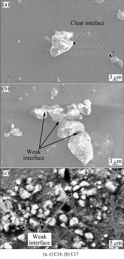
Fig. 18 FESEM (a, b) and SEM (c) images of AA6061/TiC AMCs of trial runs
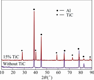
Fig. 19 XRD patterns of AA6061/TiC AMCs of trail run C24
4 Conclusions
AA6061/15%TiC AMCs were produced using the stir casting method. An empirical relationship incorporating the stir casting parameters was developed to predict the UTS. Various stir casting parameters such as stirring speed, stirring time, blade angle and casting temperature considerably influenced the UTS. A lower or higher combination of those parameters resulted in lower UTS. This was attributed to the formation of porosity, cluster of particles and segregation of TiC particles at the grain boundaries. An intermediate range of parameters yielded castings with homogeneous distribution of TiC particles and minimum porosity. The UTS was high when the porosity was low and the distribution was homogenous. The present research work revealed an existence of optimum range of parameters to produce AA6061/15%TiC (mass fraction) AMCs with high UTS. The selection and control of stir casting parameters are essential to minimize porosity content and achieve uniform distribution to enhance the load bearing capacity of the AMCs.
References
[1] AMIRKHANLOU S, REZAEI M R, NIROUMAND B, TOROGHINEJAD M R. High-strength and highly-uniform composites produced by compocasting and cold rolling processes [J]. Materials and Design, 2011, 32: 2085-2090.
[2] YIGEZU B S, VENKATESWARLU D, MAHAPATRA M M, JHA P K, MANDAL N R. On friction stir butt welding of Al + 12Si/ 10 wt%TiC in situ composite [J]. Materials and Design, 2014, 54: 1019-1027.
[3] AMIRKHANLOU S, JAMAATI R, NIROUMAND B, TOROGHINEJAD M R. Manufacturing of high-performance Al356/SiCp composite by CAR process [J]. Materials and Manufacturing Processes, 2011, 26: 902-907.
[4] GLADSTON J A K, SHERIFF N M, DINAHARAN I, SELVAM J D R. Production and characterization of rich husk ash particulate reinforced AA6061 aluminum alloy composites by compocasting [J]. Transactions of Nonferrous Metals Society of China, 2015, 25: 683-691.
[5] JI F, MA M Z, SONGA A J, ZHANGA W G, ZONGA H T, LIANG S X, OSAMUC Y, LIU R P. Creep behavior of in situ TiCP/2618 aluminum matrix composite [J]. Materials Science and Engineering A, 2009, 506: 58-62.
[6] BIROL Y. In situ synthesis of Al-TiCp composites by reacting K2TiF6 and particulate graphite in molten aluminium [J]. Journal of Alloys and Compounds, 2008, 454: 110-117.
[7] SHARMA A. Synthesis of TiC composite by salt route and grain refinement of aluminium alloy [J]. International Journal of Cast Metals Research, 2008, 21: 226-230.
[8] BAURI R. Optimization of process parameters for friction stir processing (FSP) of Al-TiC in situ composite [J]. Bulletin of Materials Science, 2014, 37: 571-578.
[9] THANGARASU A, MURUGAN N, DINAHARAN I, VIJAY S J. Synthesis and characterization of titanium carbide particulate reinforced AA6082 aluminium alloy composites via friction stir processing [J]. Archives of Civil and Mechanical Engineering, 2015, 15: 324-334.
[10] YIGEZU B S, JHA P K, MAHAPATRA M M. The key attributes of synthesizing ceramic particulate reinforced Al-based matrix composites through stir casting process: A review [J]. Materials and Manufacturing Processes, 2013, 28: 969-979.
[11] HASHIM J, LOONEY L, HASHMI M S J. Metal matrix composites: Production by the stir casting method [J]. Journal of Materials Processing Technology, 1999, 92-93: 1-7.
[12] TAHA M A. Practicalization of cast metal matrix composites (MMCCs) [J]. Materials and Design, 2001, 22: 431-441.
[13] BALASUBRAMANIAN I, MAHESWARAN R. Effect of inclusion of SiC particulates on the mechanical resistance behaviour of stir-cast AA6063/SiC composites [J]. Materials and Design, 2015, 65: 511-520.
[14] KOK M. Production and mechanical properties of Al2O3 particle- reinforced 2024 aluminium alloy composites [J]. Journal of Materials Processing Technology, 2005, 161: 381-387.
[15] GOPALAKRISHNAN S, MURUGAN N. Production and wear characterisation of AA 6061 matrix titanium carbide particulate reinforced composite by enhanced stir casting method [J]. Composites: Part B, 2012, 43: 302-308.
[16] KALAISELVAN K, MURUGAN N, PARAMESWARAN S. Production and characterization of AA6061-B4C stir cast composite [J]. Materials and Design, 2011, 32: 4004-4009.
[17] HEMANTH J. Quartz (SiO2p) reinforced chilled metal matrix composite (CMMC) for automotive applications [J]. Materials and Design, 2009, 30: 323-329.
[18] ASHOK KUMAR B, MURUGAN N. Metallurgical and mechanical characterization of stir cast AA6061-T6-AlNp composite [J]. Materials and Design, 2012, 40: 52-58.
[19] RAMESH C S, KESHAVAMURTHY R, CHANNABASAPPA B H, AHMED A. Microstructure and mechanical properties of Ni-P coated Si3N4 reinforced Al6061 composites [J]. Materials Science and Engineering A, 2009, 502: 99-106.
[20] AKBARI M K, BAHARVANDI H R, SHIRVANIMOGHADDAM K. Tensile and fracture behavior of nano/micro TiB2 particle reinforced casting A356 aluminum alloy composites [J]. Materials and Design, 2015, 66: 150-161.
[21] LEKATOU A, KARANTZALIS A E, EVANGELOU A, GOUSIA V, KAPTAY G,  Z, BAUMLI P, SIMON A. Aluminium reinforced by WC and TiC nanoparticles (ex-situ) and aluminide particles (in-situ): Microstructure, wear and corrosion behavior [J]. Materials and Design, 2015, 65: 1121-1135.
[22] SUDARSHAN, SURAPPA M K. Synthesis of fly ash particle reinforced A356 Al composites and their characterization [J]. Materials Science and Engineering A, 2008, 480: 117-124.
[23] LI Q, ROTTMAIR C A, SINGER R F. CNT reinforced light metal composites produced by melt stirring and by high pressure die casting [J]. Composites Science and Technology, 2010, 70: 2242-2247.
[24] HASHIM J, LOONEY L, HASHMI M S J. Particle distribution in cast metal matrix composites―Part I [J]. Journal of Materials Processing Technology, 2002, 123: 251-257.
[25] HASHIM J, LOONEY L, HASHMI M S J. Particle distribution in cast metal matrix composites―Part II [J]. Journal of Materials Processing Technology, 2002, 123: 258-263.
[26] NAI S M L, GUPTA M. Influence of stirring speed on the synthesis of Al/SiC based functionally gradient materials [J]. Composite Structures, 2002, 57: 227-233.
[27] NAHER S, BRABAZON D, LOONEY L. Simulation of the stir casting process [J]. Journal of Materials Processing Technology, 2003, 143-144: 567-571.
[28] AKHLAGHI F, LAJEVARDI A, MAGHANAKI H M. Effects of casting temperature on the microstructure and wear resistance of compocast A356/SiCp composites: A comparison between SS and SL routes [J]. Journal of Materials Processing Technology, 2004, 155-156: 1874-1880.
[29] PRABU S B, KARUNAMOORTHY L, KATHIRESAN S, MOHAN B. Influence of stirring speed and stirring time on distribution of particles in cast metal matrix composite [J]. Journal of Materials Processing Technology, 2006, 171: 268-273.
[30] RAVI K R, SREEKUMAR V M, PILLAI R M, MAHATO C, AMARANATHAN K R, ARUL KUMAR R, PAI B C. Optimization of mixing parameters through a water model for metal matrix composites synthesis [J]. Materials and Design, 2007, 28: 871-881.
[31] AMIRKHANLOU S, NIROUMAND B. Synthesis and characterization of 356-SiCp composites by stir casting and compocasting methods [J]. Transactions of Nonferrous Metals Society of China, 2010, 20(S): s788-s793.
[32] ZHANG H, GENG L, GUAN L, HUANG L. Effects of SiC particle pretreatment and stirring parameters on the microstructure and mechanical properties of SiCp/Al-6.8Mg composites fabricated by semi-solid stirring technique [J]. Materials Science and Engineering A, 2010, 528: 513-518.
[33] GUAN Li-na, GENG Lin, ZHANG Hong-wei, HUANG Lu-ju. Effects of stirring parameters on microstructure and tensile properties of (ABOw+SiCp)/6061Al composites fabricated by semi-solid stirring technique [J]. Transactions of Nonferrous Metals Society of China, 2011, 21(S2): s274-s279.
[34] SAJJADI S A, EZATPOUR H R, PARIZI M T. Comparison of microstructure and mechanical properties of A356 aluminum alloy/Al2O3 composites fabricated by stir and compo-casting processes [J]. Materials and Design, 2012, 34: 106-111.
[35] DU Y, ZHANG P, ZHANG J, YAO S. Radial distribution of SiC particles in mechanical stirring of A356-SiCp liquid [J]. Journal of Materials Science and Technology, 2012, 28: 951-955.
[36] AKBARI M K, MIRZAEE O, BAHARVANDI H R. Fabrication and study on mechanical properties and fracture behavior of nanometric Al2O3 particle-reinforced A356 composites focusing on the parameters of vortex method [J]. Materials and Design, 2013, 46: 199-205.
[37] KHOSRAVI H, BAKHSHI H, SALAHINEJAD E. Effects of compocasting process parameters on microstructural characteristics and tensile properties of A356-SiCp composites [J]. Transactions of Nonferrous Metals Society of China, 2014, 24: 2482-2488.
[38] FERNANDUS M J, SENTHILKUMAR T, BALASUBRAMANIAN V, RAJAKUMAR S. Optimising diffusion bonding parameters to maximize the strength of AA6061 aluminium and AZ31B magnesium alloy joints [J]. Materials and Design, 2012, 33: 31-41.
[39] VETTIVEL S C, SELVAKUMAR N, NARAYANASAMY R, LEEMA N. Numerical modelling, prediction of Cu-W nano powder composite in dry sliding wear condition using response surface methodology [J]. Materials and Design, 2013, 50: 977-996.
[40] MURUGAN N, ASHOK KUMAR B. Prediction of tensile strength of friction stir welded stir cast AA6061-T6/AlNp composite [J]. Materials and Design, 2013, 51: 998-1007.
[41] SATHISKUMAR R, MURUGAN N, DINAHARAN I, VIJAY S J. Prediction of mechanical and wear properties of copper surface composites fabricated using friction stir processing [J]. Materials and Design, 2014, 55: 224-234.
[42] ROSTAMIYAN Y, FEREIDOON A, REZAEIASHTIYANI M, MASHHADZADEH A H, SALMANKHANI A. Experimental and optimizing flexural strength of epoxy-based nanocomposite: Effect of using nano silica and nano clay by using response surface design methodology [J]. Materials and Design, 2015, 69: 96-104.
[43] BOX G E P, HUNTER W H, HUNTER J S. Statistics for experiments [M]. New York: Wiley, 1978.
[44] MONTGOMERY D G. Design and analysis of experiments [M]. Hoboken: Wiley, 2001.
[45] ROHATGI P K, SOBCZAK J, ASTHANA R, KIM J K. Inhomogeneities in silicon carbide distribution in stirred liquids― A water model study for synthesis of composites [J]. Materials Science and Engineering A, 1998, 252: 98-108.
[46] BUI R T, OUELLET R, KOCAEFE D A. Two-phase flow model of the stirring of Al-SiC composite melt [J]. Metallurgical and Materials Transactions B, 1994, 25: 607-618.
[47] OURDJINI A, CHEW K C, KHOO B T. Settling of silicon carbide particles in cast metal matrix composites [J]. Journal of Materials Processing Technology, 2001, 116: 72-76.
[48] HEIDARY D S B, AKHLAGH F. Rheological behavior of molten Al-SiC slurries and comparison of their behavior with metallic slurries [J]. Metals and Materials International, 2013, 19: 767-775.
[49] AVNER S H. Introduction to physical metallurgy [J]. New York: McGraw Hill Education, 1974.
[50] ZHANG J, FAN Z, WANG Y Q, ZHOU B L. Equilibrium pseudo binary Al-Mg2Si phase diagram [J]. Materials Science Technology, 2001, 17: 494-496.
[51] GUPTA M, LU L, ANG S E. Effect of microstructural features on the ageing behaviour of Al-Cu/SiC metal matrix composites processed using casting and rheocasting routes [J]. Journal of Materials Science, 1997, 32: 1261-1267.
[52] TZAMTZIS S, BAREKAR N S, BABU N H, PATEL J, DHINDAW B K, FAN Z. Processing of advanced Al/SiC particulate metal matrix composites under intensive shearing―A novel rheo process [J]. Composites: Part A, 2009, 40: 144-151.
[53] SELVAM J D R, SMART D R S, DINAHARAN I. Microstructure and some mechanical properties of fly ash particulate reinforced AA6061 aluminum alloy composites prepared by compocasting [J]. Materials and Design, 2013, 49: 28-34.
[54] BAURI R, YADAV D, SUHAS G. Effect of friction stir processing (FSP) on microstructure and properties of Al-TiC in situ composite [J]. Materials Science and Engineering A, 2011, 528: 4732-4739.
[55] LLOYD D J. Particle reinforced aluminium and magnesium matrix composites [J]. International Materials Reviews, 1994, 39: 1-23.
[56] ZARGHANI A S, BOZORG S F K, GERLICH A P. Strengthening analyses and mechanical assessment of Ti/Al2O3 nano-composites produced by friction stir processing [J]. Materials Science and Engineering A, 2015, 631: 75-85.
[57] AHMAD S N A S, HASHIM J, GHAZALI M I. Effect of porosity on tensile properties of cast particle reinforced MMC [J]. Journal of Composite Materials, 2007, 41: 575-589.
J. JEBEEN MOSES1, I. DINAHARAN2, S. JOSEPH SEKHAR1
1. Department of Mechanical Engineering, St. Xavier’s Catholic College of Engineering, Nagercoil 629003, Tamil Nadu, India;
2. Department of Mechanical Engineering Science, University of Johannesburg, Auckland Park Kingsway Campus, Johannesburg 2006, South Africa
摘 要:采用搅拌铸造工艺制备AA6061/15%TiC (质量分数)铝基复合材料。构建一个经验公式用于预测搅拌铸造工艺参数对AA6061/TiC铝基复合材料极限抗拉强度的影响。采用有4因素、5水平组成的中心旋转组合设计方案来减少搅拌铸造实验次数。实验因素包括搅拌速率、搅拌时间、搅拌叶片角度和铸造温度。采用所建立的经验公式和显微组织观察分析这些因素对AA6061/TiC铝基复合材料极限抗拉强度的影响。分析结果表明:上述各因素均显著影响复合材料的极限抗拉强度。复合材料极限抗拉强度的变化归因于孔隙率、团簇的形成、TiC颗粒在晶界的偏析及其在铝基体中的均匀分布。
关键词:铝基复合材料;搅拌铸造;TiC;抗拉强度
(Edited by Wei-ping CHEN)
Corresponding author: I. DINAHARAN; E-mail:dinaweld2009@gmail.com
DOI: 10.1016/S1003-6326(16)64256-5

