轴对称拉深成形法兰变形区临界压边力
来源期刊:中国有色金属学报(英文版)2012年第z2期
论文作者:秦泗吉 熊柏青 陆 宏 张婷婷
文章页码:239 - 246
关键词:板材成形;拉深;起皱;临界压边力;皱纹模型;皱纹数量
Key words:sheet metal forming; deep drawing; wrinkling; critical blank-holder force; wrinkle model; wrinkle number
摘 要:提出一种预测临界压边力的数值计算方法。对轴对称拉深成形,使用能量法分别在平面应变条件和等效应变与位置成反比关系条件下,给出法兰变形区的周向应力和等效应变与径向坐标的关系。结果表明,对于定尺寸的板坯和模具,两种假设条件下的周向应力和等效应变的最大相对误差分别为22.3%和35.9%。此外,在皱纹形状以指数函数表示的条件下,得到了压边力与皱纹数量的关系。在平面应变假设条件下,对指数分别小于1、等于1和大于1的不同皱纹形状计算了临界压边力。结果表明,皱纹的假设形状对临界压边力的计算值有较大影响。
Abstract: An analytical approach for predicting the critical blank holding force (BHF) was presented. Using energy method, the analysis provides the circumferential stress and the equivalent strain as functions of radius under the plane strain and the equivalent strain is inversely proportional to the radius respectively. The maximum relative errors of the circumferential stress and the equivalent strain are 22.3% and 35.9% respectively under the two conditions for some dimensions of sheet and die. In addition, the relationship between BHF and wrinkle number was obtained under the assumption that wrinkle shape is expressed by power function. The critical BHF under plane strain was analyzed for the wrinkle shapes when the power is less than, equal to or greater than 1. The effects of wrinkle shapes on the critical BHF are also presented.
Trans. Nonferrous Met. Soc. China 22(2012) s239-s246
QIN Si-ji1, XIONG Bai-qing2, LU Hong1, ZHANG Ting-ting1
1. Key Laboratory of Advanced Forging and Stamping Technology and Science (Ministry of Education), Yanshan University, Qinhuangdao 066004, China;
2. State Key Laboratory for Fabrication and Process of Nonferrous Metals, Beijing General Research Institute for Nonferrous Metals, Beijing 100088, China
Received 28 August 2012; accepted 25 October 2012
Abstract: An analytical approach for predicting the critical blank holding force (BHF) was presented. Using energy method, the analysis provides the circumferential stress and the equivalent strain as functions of radius under the plane strain and the equivalent strain is inversely proportional to the radius respectively. The maximum relative errors of the circumferential stress and the equivalent strain are 22.3% and 35.9% respectively under the two conditions for some dimensions of sheet and die. In addition, the relationship between BHF and wrinkle number was obtained under the assumption that wrinkle shape is expressed by power function. The critical BHF under plane strain was analyzed for the wrinkle shapes when the power is less than, equal to or greater than 1. The effects of wrinkle shapes on the critical BHF are also presented.
Key words: sheet metal forming; deep drawing; wrinkling; critical blank-holder force; wrinkle model; wrinkle number
1 Introduction
Wrinkling is an instability phenomenon that may occur in sheet metal forming. The analysis of wrinkling is the basis of the control of BHF.
Wrinkling instability is usually analyzed using bifurcation theory. HILL’s bifurcation and uniqueness theory initiated the general analytical study of plastic wrinkling [1]. HUTCHINSON [2] developed the bifurcation theory for structures in the plastic range. Based on this work, HUTCHINSON and NEALE [3] later studied the buckling behavior of doubly-curved sheet metal. However, BHF is not considered in the research. TRIANTAFYLLIDIS and NEEDLEMAN [4] studied this problem and analyzed the effect of blank holder stiffness on the critical buckling stress and wave number. The energy method is another approach. SENIOR [5] presented a one dimensional model and gave a wrinkling criterion using energy method, considering sheet thickness to be constant. Assumptions are made to determine the curve of the critical BHF vs punch stroke. YU and JOHNSON [6] used a two-dimensional buckling model of an elastic-plastic annular plate to determine the critical conditions and also quantitatively investigated the effects of a blank holder on the critical buckling stress and wave number. LIN et al [7] derived models of critical fracture and critical wrinkling respectively and discussed the formability of aluminium alloy sheet in the case of variable BHF. GAO et al [8] gave a formula of the critical BHF required to avoid wrinkling in the flange region accounting for friction. ZHAO [9] discussed the effect of friction coefficient and anisotropy coefficients on the critical BHF. WANG [10] investigated BHF through the theoretical analysis and experiment. Based on the work of WANG [10], LUO [11] conducted the analysis to obtain the safe region of BHF which is between the critical rupturing curve and the critical wrinkling curve. YAGAMI et al [12] investigated the effect of blank holder motion on deep drawability and showed that wrinkle elimination can be successful if wrinkles are within the allowable height range. WANG and CAO [13] studied the critical wrinkling condition of a square cup forming under the constant BHF assumption. AGRAWAL et al [14] derived a formula of the critical BHF required to avoid wrinkling of the flange in axisymmetric deep drawing process, considering the influence of thickness. SIVASANKARAN et al [15] used an artificial neural network model for predicting and avoiding surface failures such as wrinkling of sheet metals.
To simplify the calculation of strain energy, many researchers have made the assumption that equivalent strain is inversely proportional to radial coordinate by using energy method. The strain energy refers to the energy due to bending deformation and circumferential stress when wrinkling happens. However, such calculated critical BHF is not in consistence with experiment. In order to calculate the BHF accurately, the assumption of plane strain is utilized to analyze the stress and strain. The critical condition for wrinkling is given and the critical BHF is calculated. Since wrinkle shape has a great influence on the critical BHF, the curves of critical BHF vs punch stroke are calculated for different assumed wrinkling models.
2 Analysis of strain and stress in flange
2.1 Plane strain assumption
According to the characteristics of the axisymmetric deep drawing, the following assumptions are made.
1) Plane deformation in the flange, i.e., the strain, is zero in the thickness direction. It can be expressed as εz=0.
2) The equivalent stress and equivalent strain satisfy the relationship σ=Ben, where B and n are strength coefficient and hardening exponent, respectively.
3) The frictions between blank holder and sheet, and between die and sheet are neglected.
4) Bending and reverse bending are not considered. namely, the sheet bending deformation on the corner of the punch and the die is neglected.
Plane strain assumption has been used to analyze the flange deformation in axisymmetric deep drawing. Differential equilibrium equation can be expressed as
 (1)
(1)
where  and
and  denote the normal stress in the radial direction and the normal stress in the circumferential direction respectively at r=ρ; dσρ represents the radial stress increment when the radius increases dρ at the time t.
According to the plane strain assumption and the definition of equivalent stress, the relationship between σρ and σθ can be obtained as
 (2)
(2)
where r is the anisotropy coefficient.
The equivalent strain can be derived as
 (3)
(3)
where ρ0 is the initial location of the material particle at the time t=0; ρ is the location of same particle at the time t.
Substituting Eq. (2) into Eq. (1) and considering the strain hardening rule which is expressed by σ=Bεn, we can obtain Eq. (4):
 (4)
(4)
Let . Substituting the boundary condition into Eq. (4), we can obtain the radial stress σρ, which is equal to
  at ρ=Rw, where Q is the BHF, h0 is the initial thickness of the sheet, μ is the friction coefficient, and Rw is the radius of material particle at the outer edge of the flange at the time t. The initial location of the material particle is R0, i.e., the radius of the sheet metal. The stress of material particle at any position ρ, where
 , and r0, the inner radius of the flange, which is the inner radius of the die when the die edge radius is neglected. Then σρ and σθ in the flange can be calculated respectively as
 (5)
(5)
 (6)
(6)
where ; x is the variable of integration,
  ; x0 is the initial location when the time t=0; x is the location when the time is t. So x0 can be expressed as
  .
.
2.2 Inversely proportional assumption
It is difficult to obtain the primitive function of the integral function from Eqs. (5) and (6). So in order to simplify the calculations, some researchers assumed that the equivalent strain is inversely proportional to the radial coordinates. When m=0, using the equilibrium equations, the Tresca yield criterion and boundary conditions, the stress in the flange can be obtained as [7-11]
 (7)
(7)
 (8)
(8)
 (9)
(9)
Figure 1 shows the relationship between the ratio of circumferential stress and intensity coefficient, σθ/B, and the ratio of radial coordinate and sheet initial radius, ρ/R0. Figure 2 demonstrates relation between the equivalent strain, ε, and the ratio of radial coordinate and sheet initial radius, ρ/R0, under the two different assumptions when r=1, Rw/R0=0.85, n=0.19, r0=50 mm, R0=110 mm.
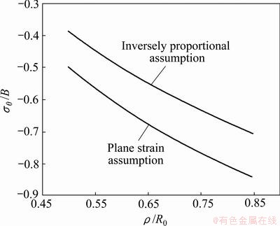
Fig. 1 Ratio of circumferential stress and intensity coefficients under two assumptions
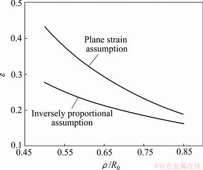
Fig. 2 Equivalent strain under two assumptions
Figures 1 and 2 show that the circumferential stresses are different under the two different assumptions, so are the equivalent strains. The maximum relative error of the circumferential stress is 22.3%, and that of the equivalent strain is greater, which is 35.9%. The circumferential stress and the equivalent strain are needed in order to calculate the BHF when the energy method is used. Hence, the blank holder forces calculated according to the circumferential stress and the equivalent strain under two assumptions are different.
It should be noted that the assumption that the equivalent strain is inversely proportional to the radius is not in accordance with the constant volume condition. Thus, the stress solution obtained in this way is not accurate. It is also necessary to adopt the later assumption in calculating the BHF, predicting the wrinkling and comparing the results obtained by using the two assumptions.
3 Calculation of strain energy
3.1 Basic equations
Let us consider a single wrinkle. According to the well-known energy method, the energy Uθ due to the compressive circumferential stress can be written as

where Uθ is strain energy due to circumferential stretching of sheet after wrinkling; Uw is strain energy due to bending stress during wrinkling; UQ is the work done by the blank holder force.
For a micro-ring with inner radius and outer radius r+dr, its cross section area is hdr. There are a number of wrinkles. For a single wrinkle of the micro-ring, let l be the original circumferential length, and
  be the increment of circumferential length when the wrinkling happens. Then the strain energy released by the circumferential stress can be obtained.
 (10)
(10)
where  ,
,  and dx represent the micro circumferential lengths of micro-ring of the single wrinkle after wrinkling and before wrinkling respectively. When the wrinkle magnitude is very small,
  can be expressed by

Deflection at any point of the single wrinkle is generally assumed to be [7]

where y0 is wrinkle amplitude;  is the angle of arbitrary point in the single wrinkle; y is the deflection of the point at any position (r,) in the flange;
  and
and  are the functions of r and respectively, which are dimensionless and mutually independent.
Substituting  into Eq. (11), we can get


 (11)
(11)
where 0 is the angle of the arc corresponding to the single wrinkle. When ρ is an arbitrary value and =0 or =0, y=0; when  and =0/2, y=y0.
The bending energy that is required to make the wrinkle formed for a single wrinkle can be calculated by
 (12)
(12)
where dI is the moment of inertia of cross-sectional area of the micro-ring. The inner radius of the ring is r. The thickness and the width of the cross section are h and dr respectively. And dI can be expressed by

Substituting  into Eq. (12), we have
 (13)
(13)
When the swift strain hardening rule is used, we have

where D is the plastic tangential modulus.
Let


Substituting the two equations into Eq. (10) and Eq. (13) respectively, we obtain
 (14)
(14)
 (15)
(15)
In the following analysis, Uθ and Uw are calculated based on the two different assumptions.
3.2 Inversely proportional assumption
Under the condition that the equivalent strain is inversely proportional to the radial coordinate, substituting the circumferential stress calculated from Eq. (9) into Eq. (14) and let

The energy released by the circumferential stress for a single wrinkle can be written as
 (16)
(16)
Because the equivalent strain is inversely proportional to the radial coordinate, we have
 (17)
(17)
Substituting Eq. (17) into Eq. (15), we can obtain

where .
.
After the integration, we obtain
 (18)
(18)
Equations (16) and Eq. (18) are obtained under the condition that the equivalent strain is inversely proportional to the radial coordinate. This condition is contradictory with that of constant volume which is the basic assumption commonly used in the plastic forming.
3.3 Plane strain assumption
Under the condition of plane strain and constant volume,  and UQ are calculated.
In order to simplify and compare the results of the two kinds of calculations, let μ=0. Substituting Eq. (6) into Eq. (14), we can get

 (19)
(19)
where  is inversely proportional to 0 and is calculated by

Equation (19) shows that is the function of Rw and contains many integral terms. Therefore, the numerical method is generally required to calculate the results.
Using the definition of the equivalent strain and the plane strain assumption, the plastic tangential modulus D can be obtained as
 (20)
(20)
Substituting Eq. (20) into Eq. (15), we can obtain
 (21)
(21)
where gw(0) is inversely proportional to  and is written by

4 Calculation of critical BHF
4.1 BHF under wrinkling condition
From the above analysis, we can get the relationship between the BHF and other parameters by using the energy method based on the latter assumption of the wrinkling model. Let N be the number of the wrinkles, Q be the BHF, then . The work done by the BHF for each wrinkle is obtained.

According to the principle of energy conservation, we can obtain
 (22)
(22)
When the friction is not considered in Eq. (22), since Q is not included in , it can be obtained directly.
When friction is considered, the energy released by the circumferential stress consists of two parts: and  , where is the value calculated by Eq. (19) without considering the friction and is the energy consumption caused by friction force. Substituting the term that contains
  in Eq. (6) into Eq. (10), we can obtain
 (23)
(23)
where Km is dimensionless coefficient and is calculated by  .
.
Substituting  into in Eq. (22), BHF can be expressed as

or

 (24)
(24)
When the assumption that equivalent strain is inversely proportional to the radial coordinate is used, substituting Eq. (16) and Eq. (18) into Eq. (22) and considering friction, Eq. (24) becomes

 (25)
(25)
When forming conditions, such as forming speed and temperature, are not considered, Eq. (24) and Eq. (25) give the relationship among the BHF and material properties parameters, geometric parameters of the sheet metal, punch stroke and wrinkle model parameters. The BHF changes only with the wrinkling model parameters when the forming conditions and other above parameters remain unchanged.
4.2 Critical BHF
The BHF is the function of the wrinkling model parameters when other parameters have been given. The wrinkle amplitude is generally allowed to be set a certain magnitude under the critical wrinkling condition, and the BHF is only the function of the wrinkle number N or the corresponding central angle of a single wrinkle, 0. The critical BHF can be obtained by substituting 0 into Eq. (24) and Eq. (25). The magnitude of 0 under the critical BHF condition can be obtained from Eq. (24) and Eq. (25) by using  .
.
Figure 3 shows the relation of Q/y0 vs the number of wrinkles when Rw/R0=0.85 and μ=0.1, where Q is the critical BHF. When the number of wrinkles is a certain value, the BHF reaches the maximum which is the critical BHF.
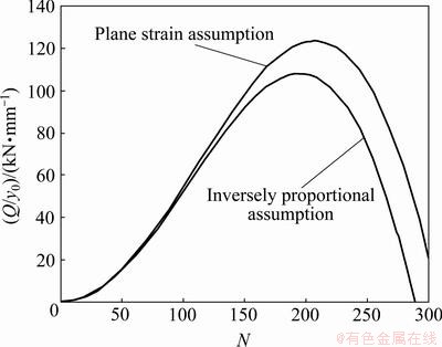
Fig. 3 Q/y0vs number (N) of wrinkles (Rw/R0=0.85, μ=0.1)
In the actual drawing process, the critical BHF is the function of the punch stroke in the case that other parameters remain unchanged. The relationship between Q/y0 and Rw/R0 is shown in Fig. 4. Rw denotes the position of outer edge of the flange that changes with the punch stroke. The calculated critical BHF under the plane strain assumption is greater than that when the equivalent strain is inversely proportional to the radial coordinate. The critical blank holder forces are both zero at the start and the end positions in the drawing process, while the BHF reaches the maximum at a certain position during the process.
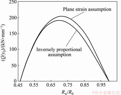
Fig. 4 Curves of critical BHF vs stroke (μ=0)
Generally, wrinkling can always be eliminated in the deep drawing process when the applied BHF is not less than the critical BHF.
5 Influence of wrinkle model on critical BHF
As stated in subsection 3.1, the wrinkle model in flange is generally assumed as
Referring to the function used in Eq. (13), it can be revised as

where m is a parameter greater than zero.
Figure 5 demonstrates the shapes of the wrinkle curve along radial direction with different m. When value of m changes, the shapes of the wrinkles are different, while the largest height of the wrinkles is the same. The BHF is mainly applied to the outer edge of the flange where the thickness of the sheet is the greatest after drawing process. The shapes of the wrinkles are convex when m<1, while they are straight or concave when m=1 or m>1 respectively. Generally, the wrinkle shapes are in accordance with experimental result when m<1. Thus the value of m corresponding to the possible shapes of wrinkles in the flange is not greater than 1.0.

Fig. 5 Shapes of wrinkles along radial direction
Substituting and
and  for different m into Eq. (10) and Eq. (13), we can get
 (26)
(26)
 (27)
(27)
The strain energy and  can be obtained by substituting Eq. (9) and Eq. (20) into Eq. (26) and Eq. (27) respectively. The critical BHF can be obtained by Eq. (22).
Figure 6 shows the critical BHF curves corresponding to different m. The results show that the shape of the wrinkle has a great effect on the calculated results of the critical BHF. The greater the value of m is, the smaller the critical BHF obtained is.
Under the experimental conditions, there is no uniform standard to determine the onset of wrinkling, so it is difficult to accurately obtain the critical BHF. Therefore, in many cases, the critical BHF is obtained by analytical or calculation method. Many researchers [7,9-11] selected m=0.5 to calculate the critical BHF which is generally greater than the experimental results. The wrinkling occurs in the outer edge of flange at first, and then in the inner range. Thus, the value of m corresponding to the shapes of wrinkles in the flange is possibly not greater than 1. To take a smaller magnitude of m is safe for calculating the critical BHF. The allowed amplitude y0 and the actual shape of the wrinkles should be considered to calculate the critical BHF accurately.
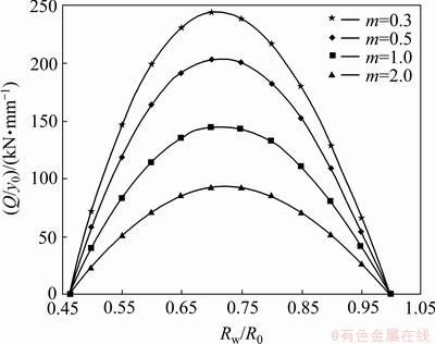
Fig. 6 Relationship between relative critical BHF and shapes of wrinkles (plane strain and μ=0)
In order to reduce the critical BHF in axisymmetric deep drawing process, we can control the wrinkle shapes corresponding to a larger m shown in Fig. 4, in which the critical BHF may be smaller by using a new deep drawing process with radial segmental blank holder, which was proposed by QIN et al [16]. By using this method, the effect of the blank holder can be enhanced.
6 Conclusions
1) The distributions of stress and strain in flange region along the radial direction for axisymmetric deep drawing were analyzed under the plane strain and the condition that the equivalent strain is inversely proportional to the radial coordinate respectively. The maximum relative errors of the circumferential stress and the equivalent strain are 22.3% and 35.9% respectively under the two conditions for some dimensions of sheet and die. The critical blank holding forces are also different.
2) The relationship between BHF and wrinkle number was obtained when wrinkling shape was expressed in terms of power function. The critical BHF under the plane strain was analyzed for the wrinkle shapes when m<1, m=1 and m>1, respectively. The critical BHF decreases as m increases.
3) The assumed wrinkling shapes have great influences on the critical BHF. Therefore, radial segmental blank holder technique can be utilized to control the wrinkle shapes to improve the formability.
References
[1] HILL R. A general theory of uniqueness and stability in elastic/plastic solids [J]. Journal of the Mechanics and Physics of Solids, 1958, 6: 236-249.
[2] HUTCHINSON J W. Plastic buckling [J]. Advances in Applied Mechanics, 1974, 14: 67-144.
[3] HUTCHINSON J W, NEALE K W. Wrinkling of curved thin sheet metal [M]. Paris: Plastic Instability Presses Ponts et Chaussées, 1985: 71-78.
[4] TRIANTAFYLLIDIS N, NEEDLEMAN A. An analysis of wrinkling in the swift cup test [J]. Journal of Engg. Materials and Technology, 1980, 102: 241-248.
[5] SENIOR B W. Flange wrinkling in deep-drawing operations [J]. Journal of the Mechanics and Physics of Solids, 1956, 48: 235-246.
[6] YU T X, JOHNSON W. The buckling of annular plates in relation to deep drawing process [J]. International Journal of Mechanical Sciences, 1982, 24(3): 175-188.
[7] LIN Zhong-qin, YU Zhong-qi, SUN Cheng-zhi, CHEN Guan-long. Formability window of aluminium alloy sheet at variable blank-holder force [J]. The Chinese Journal of Nonferrous Metals, 2005, 15(8): 1162-1166. (in Chinese)
[8] GAO K Q, DU S, HU S G. The minimum wrinkles blank-holder force for axial symmetry workpiece in deep-drawing [J]. Journal of Plasticity Engineering, 1997, 4(4): 30-37.
[9] ZHAO Jun. Study on intelligent control technology for the deep drawing of an axi-symmetric shell part [D]. Harbin: Harbin Institute of Technology, 1997. (in Chinese)
[10] WANG Dong-zhe. Research on blank holder force theory and experiment in sheet metal deep drawing [D]. Shanghai: Shanghai Jiao Tong University, 2001. (in Chinese)
[11] LUO Ya-jun. Research on blank holder force theory and numerical simulation in sheet metal deep drawing [D]. Shanghai: Shanghai Jiao Tong University, 2003. (in Chinese)
[12] YAGAMI T, MANABE K, YAMAUCHI Y. Effect of alternating blank holder motion of drawing and wrinkle elimination on deep-drawability [J]. Journal of Materials Processing Technology, 2007, 187-188: 187-191.
[13] WANG X, CAO J. An analytical prediction of flange wrinkling in sheet metal forming [J]. Journal of Manufacturing Processes, 2000, 2(2): 100-107.
[14] AGRAWAL A, REDDY N V, DIXIT P M. Determination of optimum process parameters for wrinkle free products in deep drawing process [J]. Journal of Materials Processing Technology, 2007, 191: 51-54.
[15] SIVASANKARAN S, NARAYANASAMY R, JEYAPAUL R, LOGANATHAN C. Modelling of wrinkling in deep drawing of different grades of annealed commercially pure aluminium sheets when drawn through a conical die using artificial neural network [J]. Materials & Design, 2009, 30(8): 3193-3205.
[16] QIN S J, HUANG X Z, WANG J. Research on axisymmetrical deep drawing process based on radial double blank segmental blank-holder technique [J]. Chinese Journal of Mechanical Engineering, 2011, 22(14): 1741-1744.
秦泗吉1,熊柏青2,陆 宏1,张婷婷1
1. 燕山大学 先进锻压成形技术与科学教育部重点实验室,秦皇岛 066004;
2. 北京有色金属研究总院 有色金属材料制备加工国家重点实验室,北京 100088
摘 要:提出一种预测临界压边力的数值计算方法。对轴对称拉深成形,使用能量法分别在平面应变条件和等效应变与位置成反比关系条件下,给出法兰变形区的周向应力和等效应变与径向坐标的关系。结果表明,对于定尺寸的板坯和模具,两种假设条件下的周向应力和等效应变的最大相对误差分别为22.3%和35.9%。此外,在皱纹形状以指数函数表示的条件下,得到了压边力与皱纹数量的关系。在平面应变假设条件下,对指数分别小于1、等于1和大于1的不同皱纹形状计算了临界压边力。结果表明,皱纹的假设形状对临界压边力的计算值有较大影响。
关键词:板材成形;拉深;起皱;临界压边力;皱纹模型;皱纹数量
(Edited by LI Xiang-qun)
Foundation item: Project (51175451) supported by the National Natural Science Foundation of China; Project (E2010001216) supported by Hebei Natural Science Foundation, China
Corresponding author: QIN Si-ji; Tel: +86-335-8074783; E-mail: plastics@ysu.edu.cn
DOI: 10.1016/S1003-6326(12)61714-2

