
Influence of surface modification on isothermal oxidation behavior of EB-PVD NiAl coating
LI He-fei(¿Ó∫œ∑«)1, TAO Shu-feng(Ã’ Á∑Á)2, JIANG Kuo(Ω≠ ¿´)1,
A. HESNAWI1, GONG Sheng-kai(π¨…˘ø≠)1
1. School of Materials Science and Engineering, Beijing University of Aeronautics and Astronautics,Beijing 100083, China;
2. Beijing General Research Institute of Mining and Metallurgy, Beijing 100044, China
Received 20 April 2006; accepted 30 June 2006
Abstract: The isothermal oxidation behaviors of the as-deposited NiAl coating on the nickel-based superalloy by electron beam physical vapour deposition(EB-PVD) and the NiAl coating after surface modifications of grinding and polishing were investigated. The as-deposited coating shows the least mass gain, the initially formed ¶»-Al2O3 scale spalls after only 1 h, and the succeeding scale formed is coarse and discontinuous and thus can not be used as protective coatings. Among the two surface-modified coatings, the ground coating results in the highest oxide growth rate, which is consistent with the SEM results where the scale spalls heavily and many voids appear between the scale and the NiAl coating. The scale spallation and void formation mechanisms during isothermal oxidation test of EB-PVD NiAl coating were also discussed.
Key words: thermal barrier coatings(TBCs); EB-PVD; NiAl; oxidation
1 Introduction
It is well known that NiAl intermetallic compound is considered as a candidate for high temperature structural metal material due to its low density, high melting point and high thermal conductivity[1-5]. In additional, aluminum oxide films have attracted much attention because of their desirable and superior oxidation-resistant properties. However, the Al2O3 scale formed on NiAl alloys suffers from thermal spallation due to poor adhesion between the scale and the substrate and void formation at the scale/substrate interface[6-10]. It has been reported that trace amount element addition can restrict the void formation at the scale/substrate interface, and significantly improve the scale adhesion [11-13]. However, few papers have reported the effects of surface modifications on the oxidation of EB-PVD NiAl coating. In the present study, the effects of grinding and polishing on the 1 100 °Ê oxidation behaviors of EB-PVD NiAl coating were investigated using SEM with EDS on the basis of void formation mechanisms.
2 Experimental
The material used as substrate was a Ni-based superalloy with the nominal composition varied within the following ranges (mass fraction, %): 0.03-0.08C, 19.0-22.0Cr, 0.6-1.0Al, 2.4-2.8Ti, °Ð4.0Fe, °Ð0.01B, °Ð0.01Ce, °Ð0.35Mn, °Ð0.65Si, °Ð0.007S, °Ð0.015P, while Ni being the balance. Samples with dimensions of 12 mm°¡10 mm°¡3 mm were deposited by evaporating the Ni50Al ingot. The deposition parameters were substrate temperature 850 °Ê, coating thickness 40 ¶Ãm, and depo- sition time 40 min. After deposition, some the as- deposited samples (named DP ) were picked out for later isothermal oxidation test, and the others were vacuum annealed at 1 050 °Ê for 2 h with the working pressure in the range of (3-7)°¡10-3 Pa. Two different treatments including grinding (with 2000 grit paper, named GD), polishing (with 3.5 ¶Ãm polishing paste, named PL) were carried out on the NiAl coating.
After ultrasonically cleaned with acetone and alcohol, all the modified samples adopted a 4 h vacuum heat treatment at 1 050 °Ê as pre-oxidation heat treat- ment[14]. The isothermal oxidation consisted of 100 h exposure at 1 100 °Ê in air. Each sample was placed in an alumina crucible, and the crucibles were then placed into the furnace and heated to the desired temperature. The samples were then taken out at the specified time intervals and cooled down in dry air to room temperature for the mass measurements and later analysis. The mass gains were measured by an analytical balance with an accuracy of 0.1 mg. In the tests, the samples were secured in the crucible so that the spalled oxides could be weighed together. Following oxidation, morphologies of the surfaces and cross sections of the samples were examined by scanning electron microscopy(SEM), and the distributions of elements were analyzed by energy dispersive spectroscopy(EDS). Phase identifications of oxide scales were made by XRD with Cu K¶¡ as a target.
3 Results and discussion
3.1 Oxidation kinetics and microstructure observa- tions
Fig.1 shows the isothermal oxidation kinetics of the substrate (GH33), the as-deposited sample, and the samples adopted grinding and polishing. In general, the samples with coatings exhibit obvious lower oxidation rate than the substrate. Among them, after 100 h, the mass gains of the as-deposited specimens, the specimens adopted grinding and polishing are almost the same, while the oxidation rate of the ground samples is the highest.
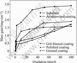
Fig.1 Mass gain vs exposure time curves of various coatings oxidized at 1 100 °Ê in air
The difference can be regarded as the result of the composition and structure diversities caused by different surface modification methods. The measured kinetics in wide temperature ranges does not closely accord to the parabolic law. The deviations are due to the phase transformations (including oxide phases and bulk material phases both in the coating and in the substrate) in different temperature ranges and oxidation stages, and the element diffusion behaviors existed in the coating system[6].
3.2 Microstructure of NiAl coatings and failure mechanisms of coating adopted grinding and polishing
Fig.2 shows the surface morphologies after 1 h and 25 h isothermal oxidation. The needle-like ¶»-Al2O3 firstly formed due to selective oxidation of Al, but the firstly formed ¶»-phase scale partly spalled only after 1 h oxidation. After the whole spallation of ¶»-phase, the oxides with the characteristic of loose and porous structure then formed on the coating surface (Fig.2(b)). The voids or grooves between the oxide ridges can be clearly observed on the coating surface. The surface micrographs of the coatings adopted grinding and polishing are shown in Figs.3(a) and (b) respectively. And Table 1 shows the main element contents of the characteristic areas (obtained by EDS) in Figs.3(a) and 3(b).
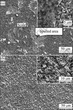
Fig.2 Surface micrographs of as-deposited NiAl coatings: (a) After 1 h isothermal oxidation; (b) After 25 h isothermal oxidation
There exist spalled areas (Area B in Fig.3(a) and Area D in Fig.3(b)) on the surface of the samples adopted grinding and polishing in which the oxygen contents (5.68% shown in Table 1 for specimen adopted grinding, nominated as GD-B; 0% for specimen adopted

Fig.3 SEM top views of coatings after 25 h oxidation in air at 1 100 °Ê: (a) Coating adopted grinding; (b) Coating adopted polishing
Table 1 Main element contents of characteristic areas shown in Fig.3 (mole fraction, %)
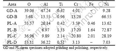
ploshing, norminated as PL-D) are significantly low Figs.4(a) and (b) are the magnified SEM top views of the specimen adopted grinding after 25 h isothermal oxidation. It is evident that there exist two layers of scales including the outer scale 1 and the inner scale 2 on the coating surface, and the corresponding spalled areas including the spalled area 1 and the spalled area 2. It is obvious that the spalled area 1 is more protruding than the spalled area 2, and the spalled area 2 distinguishes from the spalled area 1, in which many voids exist on its surface, which at the same time implies that between the scale 2 (which spalled from the spalled area 2) and the underlying metal, many voids form during the isothermal oxidation test.
After spallation of the scale 2, the smooth walls of the grain boundaries shown in Fig.4(b) may imply that no oxides have °Æpacked°Ø the grain boundaries or the oxides existed in the grain boundary can spall with scale
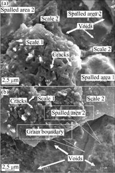
Fig.4 Voids (a) and grain boundaries (b) exposed after scales spalled from coating (ground coating, after 25 h)
2 easily. In combination with the relative higher mass gain shown in Fig.1 (adopted grinding), this surface modification method cannot be used for NiAl coating fabricated by EB-PVD.
Fig.5 shows the schematic drawing for the scale spallation mechanism of NiAl coating adopted grinding during the isothermal oxidation test at 1 100 °Ê in air. The upper part is the suppositional top views after removing the scales; the lower part is the A°™A cross-section of the upper part but with the scales. At the initial stage of oxidation, aluminum oxides (scale 1) firstly form with characteristic of porous structure and distributed cracks due to selective oxidation of aluminum. scale 2 forms because of inward diffusion of O through scale 1, and outward diffusion of Ni, Cr and Ti from the substrate to the Scale 1/metal interface. The continuity of scale 2 above the voids can be kept by the supply of Al evaporating from the metal[6, 7], and because of this effect, the grain boundary becomes deeper and wider. Even though these voids distribute here and there under scale 2, the voids tend to congregate to the grain boundaries, and if these voids connect and coalesce with each other, the larger voids and long grooves may form.
After 25 h oxidation, the cross-sectional micro- graphs of the specimens adopted polishing are shown in Fig.6 and the corresponding element distributions obtained by EDS are also shown in Table 2. The high oxygen concentrations indicate that spots indicated by 1, 2 and 3 are the internal oxides. Sometimes, there exist
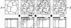
Fig.5 Schematic drawing of scale spallation mechanism for coating adopted grinding during isothermal oxidation test
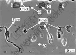
Fig.6 Micrograph of cross-sections of specimen adopted polishing after 25 h isothermal oxidation
core-like holes in the center of the internal oxide (Area 1 and Area 3 in Fig.6), and the core connects with the outer scales on the coating surface by some routes (crack shown in Fig.6). The O content in the inner part (Point B,
56.99%) and that in the outer ring (Point C, 59.21%) of the internal oxide 2 (Fig.6) are almost the same, but the total composition (42.73%) of other elements (Al, Ni, Cr and Ti) in the inner part (Ni, Cr, Ti and Al) matches with that of Al (40.79%) in the outer ring. This may imply that the inner layer of oxides must be different from the outer layer and be composed of other oxide beside Al2O3.
Table 2 Main element concentrations of characteristic areas shown in Fig.6
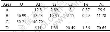
Fig.7 shows the SEM morphologies and the element maps of the specimen adopted polishing after 50 h isothermal oxidation at 1 100 °Ê. Many holes and grooves can be observed on the coating surface. And around these holes and grooves, there exist alumina belts that separate the holes and grooves from the spalled areas. So some alumina belts locate in the spalled areas isolating from the other scales to form the isolate °∞oxide islands°±, the others protrude from the °∞scale main lands°± to the spalled areas to form the °∞oxide peninsula°±.
As shown in the schematic diagram Figs.8(a) and8(b), the area joining the inner scale and the surface scale is the easily broken area because of high stress concen-
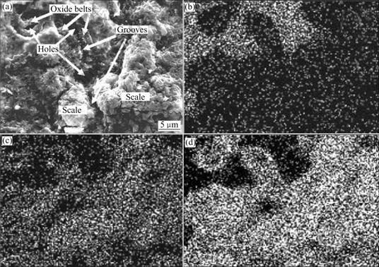
Fig.7 Surface morphology (a) and elemental distribution maps (b-d) of specimen adopted polishing after 50 h isothermal oxidation
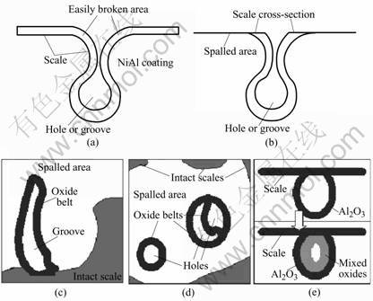
Fig.8 Schematics showing scale spallation near holes or grooves formed during oxidation test: (a) Scale on inner surface of hole (groove) connect with scale on coating surface; (b) Scales break at easily broken area and cross-section of inner scale were exposed; (c) Peninsula-like oxide forms after part of easily broken area still connects with scale mainland; (d) Isolate island-like oxides form after completely spallation of easily broken area; (e) Selective oxidation of Al results in formation of Al2O3 film, and then diffusion of Al ,Ni, Ti and Cr through formed Al2O3 film and succeeding oxidation causes difference between inner part and outer part of internal oxide
tration. If the stress is high enough to reach the fracture limit of the scale, the scales may break and then may spall from this area, so the cross sections of the inner scale should be exposed and result in the formation of the oxidized belt (if seen from top view). This not only can explain the fact that there are oxidized belts around the holes or grooves shown in Figs.8(a) and (b), but also can explain the formation of the isolated oxides and oxide peninsulas. For if part of the easily broken area spall from and part of it still connect with the scale mainland, thus from top view, the oxide should be observed as a peninsula extending from the °∞scale mainland°± to the spalled area (Fig.8(c)). And if the easily broken area spalls completely, the isolate oxides should develop with the island shape in spalled area (Fig.8(d)). Furthermore, if the easily broken area still remains intact and connects with the scale mainland, it is evident to find the grooves or holes in the scale from the SEM top views, but because the oxide belts are mainly Al2O3, so from the O and Al maps shown in Fig.7, the grooves and holes can not be differentiated from the scale mainland. Fig.8(e) is the schematic drawing showing the mechanism of the formation and development of the internal oxides. The aluminum oxide film forms firstly on the inner side of grooves and holes because selective oxidation of aluminum. That is why the SEM/EDS results show that the outer ring of the internal oxides is Al2O3, and then the elements of Al, Ni, Ti and Cr (Ti and Cr diffused from the substrate) may diffuse through the Al2O3 film and cause the formation of other oxides such as Ni(Al,Cr)2O4 and TiO2 by analysis of element contents shown in Table 2.
4 Conclusions
1) Isothermal oxidation tests have been performed at 1 100 °Ê on EB-PVD NiAl coatings modified by grinding and polishing, all the coated samples exhibit obvious lower oxidation rate than the substrate.
2) The porous structure of the as-deposited coating is not fit for being as bond coat for TBCs.
3) For the ground coating, the scale spallation is mainly due to the voids under the scale formed near the substrate.
4) For the polished coating, the easily broken areas that link the scales on surface and inside grooves (holes) often result in the scale spallation.
Acknowledgement
The authors would like to thank ZHOU Chun-gen for profitable discussion about SEM/EDS analysis.
References
[1] KIM S H, OH M H, KISHIDA K, HIRANO T, WEE D M. Deposition of NiAl coating for improvement of oxidation resistance of cold-rolled Ni3Al foils [J]. Intermetallics, 2005, 13: 129-136.
[2] LACAZE J, LUPKER M, VIALAS N, MONCEAU D. Application of image analysis and image simulation for quantitative characteriza- tion of scale spallation during cyclic oxidation of a Pt-aluminide coating [J]. Intermetallics, 2006, 14: 423-434.
[3] LEYENS C, PINT B A, WRIGHT I G. Effect of composition on the oxidation and hot corrosion resistance of NiAl doped with precious metals [J]. Surf Coat Techol, 2000, 133-134: 15-22.
[4] SONG Wei-jie, YOSHITAKE M. Effects of surface cleaning on oxidation of NiAl(110) [J]. Appl Surf Sci, 2005, 241: 164-168.
[5] LYKHACH Y, MOROZ V, YOSHITAKE M. Formation of epitaxial Al2O3/NiAl (110) films: aluminium deposition [J]. Appl Surf Sci, 2005, 241: 250-255.
[6] GRABKE H J. Oxidation of NiAl and FeAl [J]. Intermetallics, 1999, 7: 1153-1158.
[7] BENNETT I J, SLOOF W G. The influence of reactive element additions to ¶¬-NiCrAl alloys on the morphology of thermally grown oxides [J]. Metal at High Temp, 2000: 395-403.
[8] PINT B A. The role of chemical composition on the oxidation performance of aluminide coatings [J]. Surf Coat Technol, 2004, 188-189: 71-78.
[9] GUO J T, XU C M. Effect of NiAl microcrystalline coating on the high-temperature oxidation behavior of NiAl-28Cr-5Mo-1Hf [J]. Oxid Met, 2002, 58: 458-468.
[10] PINT B A, DISTEFANO J R, WRIGHT I G. Oxidation resistance: One barrier to moving beyond Ni-base superalloy [J]. Mater Sci Eng, 2006, A415: 255-263.
[11] HAYNES J A, LANCE M J, PINT B A, WRIGHT I G. Characterization of commercial EB-PVD TBCs systems with CVD (Ni, Pt)Al bond coatings [J]. Surf Coat Technol, 2001, 146-147: 140-146.
[12] ALLEN HAYNES J. Potential influences of bond coat impurities and void growth on premature failure of EB-PVD TBCs [J]. Scripta Mater, 2001, 44: 1147-1152.
[13] RABIEI A, EVANS A G. Failure mechanisms associated with the thermally grown oxide in plasma-sprayed thermal barrier coatings [J]. Acta Mater, 2000, 48: 3963-3976.
[14] XU Hui-bin, GUO Hong-bo, LIU Fu-shun, GONG Sheng-kai. Development of gradient thermal barrier coatings and their hot-fatigue behavior [J]. Scripta Mater, 2000, 130: 133-139.
(Edited by YUAN Sai-qian)
Foundation item: Project(50571005) supported by the National Natural Science Foundation of China
Corresponding author: LI He-fei; Tel: +86-10-82317118; E-mail: 6182050@sohu.com

