An improved computation scheme of strapdown inertial navigation system using rotation technique
来源期刊:中南大学学报(英文版)2012年第5期
论文作者:张伦东 练军想 吴美平 胡小平
文章页码:1258 - 1266
Key words:strapdown inertial navigation system; rotation technique; navigation computation scheme; error characteristic
Abstract:
To improve the accuracy of strapdown inertial navigation system (SINS) for long term applications, the rotation technique is employed to modulate the errors of the inertial sensors into periodically varied signals, and, as a result, to suppress the divergence of SINS errors. However, the errors of rotation platform will be introduced into SINS and might affect the final navigation accuracy. Considering the disadvantages of the conventional navigation computation scheme, an improved computation scheme of the SINS using rotation technique is proposed which can reduce the effects of the rotation platform errors. And, the error characteristics of the SINS with this navigation computation scheme are analyzed. Theoretical analysis, simulations and real test results show that the proposed navigation computation scheme outperforms the conventional navigation computation scheme, meanwhile reduces the requirement to the measurement accuracy of rotation angles.
J. Cent. South Univ. (2012) 19: 1258-1266
DOI: 10.1007/s11771-012-1137-8![]()
ZHANG Lun-dong(张伦东), LIAN Jun-xiang(练军想), WU Mei-ping(吴美平), HU Xiao-ping(胡小平)
Department of Automatic Control, College of Mechatronics and Automation,
National University of Defense Technology, Changsha 410073, China
? Central South University Press and Springer-Verlag Berlin Heidelberg 2012
Abstract: To improve the accuracy of strapdown inertial navigation system (SINS) for long term applications, the rotation technique is employed to modulate the errors of the inertial sensors into periodically varied signals, and, as a result, to suppress the divergence of SINS errors. However, the errors of rotation platform will be introduced into SINS and might affect the final navigation accuracy. Considering the disadvantages of the conventional navigation computation scheme, an improved computation scheme of the SINS using rotation technique is proposed which can reduce the effects of the rotation platform errors. And, the error characteristics of the SINS with this navigation computation scheme are analyzed. Theoretical analysis, simulations and real test results show that the proposed navigation computation scheme outperforms the conventional navigation computation scheme, meanwhile reduces the requirement to the measurement accuracy of rotation angles.
Key words: strapdown inertial navigation system; rotation technique; navigation computation scheme; error characteristic
1 Introduction
The ring laser gyro strapdown inertial navigation system (RLG-SINS) is much more reliable, much smaller in size, and, especially, has much lower life-cycle cost than the electromechanical gimbaled system due to the omission of the electromechanical gimbaled platform [1]. So, it is now widely used as the main navigation system in many fields, such as aerospace, marine and land navigation. The same as other kinds of inertial navigation system (INS), the errors of RLG-INS also increase with time [2]. Thus, in some long term applications, the drifts of gyros and the biases of accelerometers will eventually cause the navigation errors to exceed the acceptable level, such as marine and submarine navigation applications [3]. Therefore, the effects of the gyro drift and the accelerometer bias must be reduced to obtain a higher accuracy for the RLG-INS-only system. Many techniques have been developed in the last three decades, among which the rotation technique is the most effective one. The inertial sensor cluster (3 gyros/3 accelerometers) is mounted on a rotation table, which will periodically rotate the inertial sensor cluster with one or two of its axes [4]. So, the errors of the inertial sensors can be modulated into periodically varied signals, which can remove the constant bias, slowly vary errors of the sensor, greatly improve the accuracy of SINS and maintain a sufficient accuracy for long time [5].
The systematic rotation technique does not rely on any external information, which ensures autonomy of the vehicle. Besides, this technique permits the estimation of the constant drifts in all three gyros and three accelerometers during dockside alignment [6]. And, it can improve the accuracy of the initial alignment by rotating the inertial measurement unit (IMU) [7-8]. Therefore, it has been investigated in many countries and applied to many types of products, such as MK39modC, MK49 and AN/WSN-7 [9-11].
However, the rotation table has errors. It might affect the accuracy of SINS. So, how to compute the navigation parameters is important. The literatures about the MK39modC, MK49 and AN/WSN-7 didn’t provide the navigation computation scheme. Nevertheless, YANG and MIAO [12] presented a conventional navigation computation scheme of the RLG-SINS using rotation technique, as shown in Fig. 1. Angular increments from the rotator angle measurements are used to compute a direction cosine matrix ![]() firstly. This matrix is employed to transform the body angular increments from the RLGs and the body velocity increments from the accelerometers in the sensor reference frame into the vehicle reference frame. Then, the attitude, velocity and position of the vehicle are computed using the classical strapdown algorithm. The accuracy of this navigation computation scheme relies on the stability of the rotation axis and the measurement accuracy of the rotator angle. If the rotation axis wobbles or the measurement errors of the rotator angle increase, the errors of the gyros and the accelerometers will increase. It will result in the increase of the navigation errors. Besides, the RLG-SINS cannot work when the angle measurement device of the rotator won’t go. So, this navigation computation scheme might not fit to engineering application.
firstly. This matrix is employed to transform the body angular increments from the RLGs and the body velocity increments from the accelerometers in the sensor reference frame into the vehicle reference frame. Then, the attitude, velocity and position of the vehicle are computed using the classical strapdown algorithm. The accuracy of this navigation computation scheme relies on the stability of the rotation axis and the measurement accuracy of the rotator angle. If the rotation axis wobbles or the measurement errors of the rotator angle increase, the errors of the gyros and the accelerometers will increase. It will result in the increase of the navigation errors. Besides, the RLG-SINS cannot work when the angle measurement device of the rotator won’t go. So, this navigation computation scheme might not fit to engineering application.

Fig. 1 Conventional navigation computation scheme
Considering the disadvantages of the conventional navigation computation scheme, in this work, an improved navigation computation scheme is proposed. Firstly, the sensed angular increments are approximately integrated and used to compute a direction cosine matrix ![]() . This direction cosine matrix is employed to transform the sensed velocity increments into the navigation frame, and compute the attitude, velocity and position of the IMU. The IMU only rotates about the yaw axis of the vehicle. There is no translational movement relative to the vehicle. So, the velocity and position of the vehicle are approximately the same as the IMU. The rotation angle is accurately measured at all times. This angle is used to transform the attitude of the IMU into the attitude of the vehicle. Compared with the conventional navigation scheme, this navigation scheme relaxes the requirements to the stability of the rotation axis and the measurement accuracy of the rotator angle. The RLG-SINS can work well as the conventional strapdown navigators even when the rotator assembly or the angle measurement device of the rotator will not go.
. This direction cosine matrix is employed to transform the sensed velocity increments into the navigation frame, and compute the attitude, velocity and position of the IMU. The IMU only rotates about the yaw axis of the vehicle. There is no translational movement relative to the vehicle. So, the velocity and position of the vehicle are approximately the same as the IMU. The rotation angle is accurately measured at all times. This angle is used to transform the attitude of the IMU into the attitude of the vehicle. Compared with the conventional navigation scheme, this navigation scheme relaxes the requirements to the stability of the rotation axis and the measurement accuracy of the rotator angle. The RLG-SINS can work well as the conventional strapdown navigators even when the rotator assembly or the angle measurement device of the rotator will not go.
In this work, the principle of the rotation technique is introduced based on the measurement error model of the IMU. Then, the conventional and the improved navigation schemes are discussed in detail. Moreover, the error propagation equations of the two navigation schemes are derived. The effects of the angle measurement error of the rotation angle and the rotation rate instability on the system accuracy are analyzed.
2 Basic principle of rotation technique
Formulation of the principle of the rotation technique involves the use of several coordinate frames, which are designated by the symbols “s”, “b” and “n”. The s, or sensor, frame is a Cartesian system fixed to the rotation assembly. The s-coordinate axes are directed along the axis of rotation, and in the plane perpendicular to the rotation axis. The nominal gyro/accelerometer sensitive axes are assumed to comprise an orthogonal set, and to be parallel to the axes of the s-frame. The coordinates axes of the b-Cartesian frame are defined by the roll, pitch and yaw axes of the vehicle. In the postulated system, the rotation axis is parallel to the vehicle yaw axis. The n-frame has its origin at the true position of the system, and its axes are directed toward true north, up and east.
The IMU generally consists of three almost orthogonally mounted gyroscopes and three almost orthogonally mounted accelerometers. The measurement values of the gyro cluster and the accelerometer cluster can be expressed as [13]
![]()
where ![]() denotes the ideal sensor angular velocity with respect to the inertial frame,
denotes the ideal sensor angular velocity with respect to the inertial frame, ![]() denotes the input specific force expressed in s-frame,
denotes the input specific force expressed in s-frame, ![]() and
and ![]() are the scale factor errors of the RLG and accelerometer, respectively,
are the scale factor errors of the RLG and accelerometer, respectively, ![]() and
and ![]() are the misalignment of the RLG triad and accelerometer triad, respectively, ε and
are the misalignment of the RLG triad and accelerometer triad, respectively, ε and ![]() are the fixed biases of the RLG and accelerometer, respectively, and
are the fixed biases of the RLG and accelerometer, respectively, and ![]() and
and![]() are the noises of the RLG and accelerometer, respectively.
are the noises of the RLG and accelerometer, respectively.
Ignoring the error product terms, Eq. can be written as
![]()
where ![]() and
and ![]() represent the measurement errors of the gyros and the accelerometers, respectively.
represent the measurement errors of the gyros and the accelerometers, respectively.
It is assumed that the vehicle is stationary. And at the start time, both the s-frame and b-frame coincide with the n-frame. As shown in Fig. 2, the equivalent gyro errors in the n-frame can be expressed as
![]()
where εN, εU and εE are the equivalent north, up and east gyro errors, respectively, and εx, εy and εz denote the drifts of the RLG output.

Fig. 2 Principle of rotation technique
The IMU rotates around the yaw axis of the vehicle at rotation rate ωc. At t epoch, the direction cosine matrix from b-frame to s-frame can be expressed as follows:

where α=ωct, denotes the rotation angle with respect to vehicle at t epoch, which can be measured by the angle readout device.
Considering the ![]() and
and ![]() denote the ideal input values without errors, it can be expressed as
denote the ideal input values without errors, it can be expressed as
![]()
where ![]() , and
, and ![]() .
.
Combining Eqs. , and , the drifts of the gyros and the biases of the accelerometers in n-frame can be expressed as follows:

where ![]() ,
, ![]() .
.
According to previous assumption, the b-frame coincides with the n-frame, namely, ![]() . Ignoring the δKg, δKa, δCg and δCa, Eq. can be written as
. Ignoring the δKg, δKa, δCg and δCa, Eq. can be written as
![]()
Substituting Eq. into Eq. and ignoring the noises εn and ![]() , the following equations can be derived:
, the following equations can be derived:
![]()
From Eq. , it can be found that the errors of the inertial sensors at x and z axes are modulated into periodically varied signals in the n-frame, but none of y axis. The equivalent gyro drift in the n-frame when the IMU rotates 180? relative to the vehicle can be expressed as
![]()
From Eqs. , and , it can be noted that the mathematical signs of the equivalent east and north axes gyros drifts in n-frame have an opposite change, namely, from positive to negative. Thus, the navigation errors introduced by x and z axes gyros drifts are averaged out. However, the navigation errors introduced by y axes gyros drift are not averaged out because the direction of the y gyro sensitive axis does not change.
From the above analysis, we can conclude that the essential part of the rotation technique is to rotate the IMU, and ensure that the directions of gyros and accelerometers sensitive axes have changes in n-frame according to some rules, and meanwhile, bring the rectified drift stays with the inertial sensor axis opposite to the n-frame axis. Therefore, the rotation technique averages out the inertial sensor constant drifts, yielding improved attitude, velocity and position accuracy.
3 Conventional navigation computation scheme
3.1 Basic navigation equations
The part in the dash line box in Fig. 1 is the same as the classical strapdown navigation computation diagram. According to Ref. [2], the velocity of the system fulfills the following dynamics:
![]()
where ![]() is a direction cosine matrix used to transform the measured specific force vector into navigation axes.
is a direction cosine matrix used to transform the measured specific force vector into navigation axes.
This matrix propagates in accordance with the following equation:
![]()
where ![]() is the skew symmetric form of
is the skew symmetric form of ![]() , the body rate with respect to the n-frame.
, the body rate with respect to the n-frame.
![]() can be derived by differencing the measured body rates with the estimates from the components of n-frame rate:
can be derived by differencing the measured body rates with the estimates from the components of n-frame rate:
![]()
where ![]() is the skew symmetric form of
is the skew symmetric form of![]() , the body rate with respect to the inertial frame.
, the body rate with respect to the inertial frame. ![]() is the skew symmetric form of
is the skew symmetric form of ![]() , which is obtained by summing the Earth’s rate with respect to the inertial frame and the turn rate of the n-frame with respect to the Earth, that is,
, which is obtained by summing the Earth’s rate with respect to the inertial frame and the turn rate of the n-frame with respect to the Earth, that is, ![]() .
.
From Eq. , reorganizing terms yields
![]()
where ![]() is the body rate with respect to the s-frame.
is the body rate with respect to the s-frame.
Since the rotary movement of IMU does not bring translational movement between s-frame and b-frame, ignoring the size effect parameters, the following relationship holds:
![]()
Substituting Eq. into Eq. , and Eq. into Eq. , respectively, we have
![]()
![]()
where ![]() is the skew symmetric form of
is the skew symmetric form of ![]() and
and ![]() is the skew symmetric form of
is the skew symmetric form of ![]() .
.
Equations , and are the basic formulas of conventional navigation computation scheme. From these equations, the following characteristics of this scheme can be concluded:
1) The measurement values of the gyros and accelerometers are transformed into the b-frame firstly in this navigation scheme, and then the attitude, velocity and position of the vehicle are computed using the classical strapdown navigation algorithm.
2) In order to reduce the errors of the transforming inertial measurement values into b-frame, the measurement accuracy of the rotation angle should be very precise. Otherwise, the errors will be introduced into measurement values in b-frame by rotation assembly wobbling and the angle measurement error of the rotation angle.
3) From Eq. , we can see that the measurement accuracy of the rotation angle should be equal to that of the gyro. However, it is difficult to achieve the above performance in dynamic conditions. In order to compute navigation parameters accurately, the sampling frequency of the angle measurement should be much high. It is important that the angle measurement device failures are catastrophic, and navigation cannot continue.
3.2 Error model of conventional navigation scheme
The measurement error of the rotation angle is denoted by δα, which is a small angle. Ignoring the other errors, the estimated direction cosine matrix from the s-frame to the b-frame, denoted by ![]() , can be written as
, can be written as

where f is the skew symmetric form of θ. ![]() , is the measurement error vector of the rotation angle.
, is the measurement error vector of the rotation angle.
3.2.1 Velocity and position errors
According to Eq. , the estimated velocity may be assumed to propagate in accordance with the following equation in which estimated quantities are denoted by a tilde:
![]()
where ![]() ,
, ![]() ,
, ![]() ,
, ![]() and
and ![]() represent the estimated values of ν, C, f, ω and g, respectively.
represent the estimated values of ν, C, f, ω and g, respectively.
Differencing Eqs. and , substituting for![]() ,writing
,writing![]() ,
, ![]() ,
, ![]() ,
,![]() [2], and expanding, ignoring error product terms, we have
[2], and expanding, ignoring error product terms, we have
![]()
![]()
where  is the skew symmetric matrix form of
 ![]() ,
, ![]() ,
, ![]() and
and ![]() are the level error, tilt error, and the heading error of the b-frame with respect to n-frame, respectively, and f n is the specific force vector in the n-frame.
are the level error, tilt error, and the heading error of the b-frame with respect to n-frame, respectively, and f n is the specific force vector in the n-frame.
The position errors, δp, may be expressed as
![]()
3.2.2 Attitude errors
The attitude error function of the classical SINS has been discussed by TITTERTON and WESTON [2]:
![]()
where ![]() ,
, ![]() and
and ![]() represents the measured error of the gyro in b-frame.
represents the measured error of the gyro in b-frame.
Similarly, the estimated value of ![]() is given by
is given by
![]()
Differencing Eqs. and , we have
![]()
Substituting Eq. into Eq. , writing ![]() ,
, ![]() , and expanding, ignoring error product terms, we have
, and expanding, ignoring error product terms, we have
![]()
From Eqs. and , we can see that the velocity and position errors are influenced by the measurement errors of rotation angle though the errors of the gyros and accelerometers are modulated into periodical signals by ![]() with the use of the rotation technique.
with the use of the rotation technique.
Equation shows that the attitude error functions also include the rotation angle measurement errors, f. Besides, it also includes the instability errors of the rotation rate, ![]() .
.
It is indicated that the rotation angle measurement errors and the instability of the rotation rate will degrade the accuracy of RLG-INS using rotation technique. In addition, with the vehicle acceleration and turn rate increasing, the errors induced by the angle measurement error will increase. So, the measurement error of the rotation angle should be reduced.
4 Improved navigation computation scheme
4.1 Basic navigation equations
Unlike conventional navigation computation scheme, all rates are observed by the strapdown gyros and the rotation angles are measured at all times for output attitude computation in the improved navigation computation scheme, as shown in Fig. 3.
The change rate of ![]() with respect to n-frame may be expressed in n-frame as follows:
with respect to n-frame may be expressed in n-frame as follows:
![]()
where ![]() is a direction cosine matrix used to transform the measured specific force vector into n-frame. This matrix propagates in accordance with the following equation:
is a direction cosine matrix used to transform the measured specific force vector into n-frame. This matrix propagates in accordance with the following equation:
![]()
where ![]() is the skew symmetric form of
is the skew symmetric form of ![]() , the IMU rate with respect to the n-frame. This is derived by differencing the measurement value of the gyros
, the IMU rate with respect to the n-frame. This is derived by differencing the measurement value of the gyros ![]() and estimates of the components of n-frame rate
and estimates of the components of n-frame rate ![]() .
.
The ![]() can be expressed as
can be expressed as
![]()
where ![]() is the skew symmetric form of
is the skew symmetric form of![]() .
.
The ![]() is a direction cosine matrix used to transform the specific force vector in vehicle axes into navigation axes. This matrix can be expressed as
is a direction cosine matrix used to transform the specific force vector in vehicle axes into navigation axes. This matrix can be expressed as
![]()
Equations - are the basic functions of the improved navigation computation scheme. From these functions, we can see that the characteristics of this navigation scheme can be described as follows:

Fig. 3 Improved navigation computation scheme
1) All rates are observed by the strapdown gyros to compute the attitude, velocity and position of the IMU using the classical navigation algorithm firstly. Then, it is combined with the rotation angle measurements to compute the attitude of the vehicle. It is considered that the velocity and position of the vehicle are the same as the IMU.
2) The angle measurement values of the rotation assemble is only used for output attitude computation of the vehicle. It is not used when computing the velocity and position. So, the velocity and position errors are not influenced by the measurement errors of rotation angle.
3) The sampling frequency of the angle measurement device is only equal to the attitude update frequency, so it is kept in a low sampling frequency. Especially, it is important that the navigation can continue even when the angle measurement device is in failure. Besides, the angle measurement device can be leaved out if the attitude output of the vehicle doesn’t need to be computed.
4.2 Error model of improved navigation scheme
4.2.1 Velocity and position errors
The velocity and position errors are the same as the classical strapdown navigation system because the basic functions of the improved navigation scheme are the same as the classical navigation functions in form. The velocity and position errors can be expressed as follows according to Ref. [2]:
![]()
![]()
![]()
where ![]() is the misalignment vector. The elements,
is the misalignment vector. The elements, ![]() ,
, ![]() and
and![]() , correspond to the attitude errors of the IMU with respect to the n-frame, the tilt errors, whilst represent the error about vertical, and the azimuth error, respectively. This can be expressed as follows:
, correspond to the attitude errors of the IMU with respect to the n-frame, the tilt errors, whilst represent the error about vertical, and the azimuth error, respectively. This can be expressed as follows:
![]()
4.2.2 Attitude errors
Differentiating Eq. yields
![]()
Similarly, the time differential of the estimated matrix ![]() is given by
is given by
![]()
Substituting Eq. into Eq. , ![]() is given by
is given by
![]()
Similarly, the time differential of the estimated matrix is given by
![]()
According to Ref. [2], the time differential of the attitude error can be expressed as
![]()
Substituting Eqs. , , and into Eq. and writing![]() and expanding, ignoring error product terms, we have
and expanding, ignoring error product terms, we have
![]()
![]()
The above equation may be expressed in vector form as
![]()
By equations and , we know that the velocity and position errors cannot be influenced by the rotation angle measurement errors and the instability of the rotation rate with the use of the improved navigation computation scheme. However, Eq. indicates that the attitude errors of the improved navigation scheme are of the angle measurement error f and the rotation instability![]() . That is, these errors only influence the attitude accuracy when using the improved navigation scheme.
. That is, these errors only influence the attitude accuracy when using the improved navigation scheme.
5 Simulations and real tests
5.1 Simulations
The simulation approach is used to verify the performance of the conventional and the improved navigation schemes firstly. The constant drift rates of three gyroscopes are set as 0.004 (°)/h. The stochastic noise in three gyros is Gaussian white noise, and the noise level is set as 0.001 (°)/h. The constant biases of three accelerometers are set as 10-5g. The stochastic noise in three accelerometers is Gaussian white noise, and the noise level is set as 10-5g. The gyroscope and accelerometer scale factor errors are set as 1.2×10⁻⁶ and 10×10-6, respectively. The rotation assembly rotates back and forth at a rate of 6 (°)/s about the vertical axis. The instability of this rotation rate is about 0.000 2 (°)/s. The angle measurement error is 1′. The initial attitude, velocity and position of the vehicle are zero. The initial level and heading errors are 15′′ and 1′, respectively. The vehicle was assumed to be stationary and located on the surface of the earth at latitude of 30° and longitude of 110°. Ignoring the misalignment of gyroscope and accelerometer triads, the convention and the proposed navigation scheme are compared through 24 h navigation simulation. The results of the simulation are shown in Fig. 4. The maximum navigation errors of the two different navigation computation schemes are shown in Table 1.
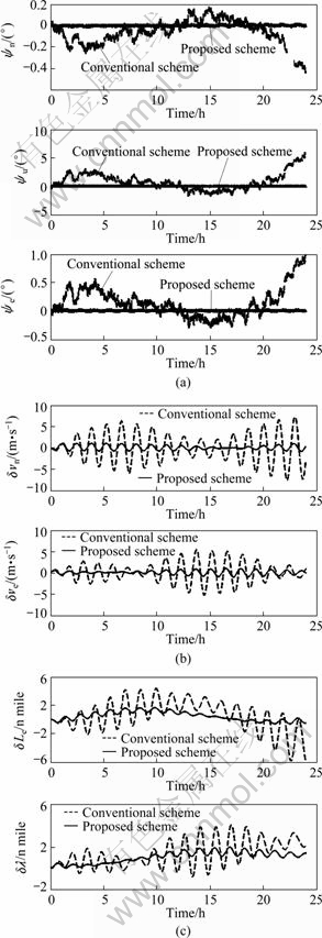
Fig. 4 Navigation errors of two different computation schemes: (a) Attitude errors; (b) Velocity errors; (c) Position errors
Table 1 Maximum navigation errors of two different navigation computation schemes
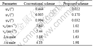
Figure 4 and Table 1 show that the accuracy of the improved navigation scheme is much better than that of the conventional navigation scheme. It is also indicated that the angle measurement error of the turntable rotation and the instability of the turntable rotation rate have much less effect on the improved scheme than on the conventional one.
5.2 Real tests of improved navigation scheme
The RLG-INS developed by our laboratory consists of IMU, turntable, electronic circuit boards, control and display panel, thermal control device and shock absorber. The IMU consists of three mechanically dithered ring laser gyroscope (the random constant drifts are about 0.004 (°)/h, and the scale factor errors are about 1×10⁻⁶) and three quartz accelerometers (the random constant biases are about 1×10⁻⁵g, and the scale factor error is about 10-5). The IMU is mounted on the turntable which rotates at a rate of 9 (°)/s around the vertical axis of the vehicle between four discrete orthogonal positions. The dwell positions are 0°, 180°, 270° and 90°, and the dwell time at each position is 300 s. The instability of this rotation rate is about 0.000 2 (°)/s. The angle measurement error is 10′′. The IMU and the turntable are installed on the shock absorber. The RLG-INS is mounted on the swing simulation table which simulates the movement of the vehicle. The photograph of this test is shown in Fig. 5. The swing simulation table is set to rotate periodically, and its rotation pattern is shown in Fig. 6. Figure 6(c) shows the composite rotation of the turntable and the swing simulation table.
A long time navigation test has been carried out using the improved navigation scheme. The navigation using the conventional scheme has not been carried out and the attitude of the vehicle is not provided, because the misalignments of the IMU with respect to the turntable are not calibrated and the turntable rotation angles are not precisely measured at all times. The IMU is warmed up for over 4 h before self-alignment. Following a 4 h self-alignment, the system is placed into navigation lasting 24 h. The velocity and position errors are shown in Fig. 7. The test without the rotation platform working has also been carried out. The navigation results of this test are shown in Fig. 8.

Fig. 5 Photograph of test

Fig. 6 Rotation patterns of swing simulation table: (a) Roll rotation; (b) Pith rotation; (c) Azimuth rotation

Fig. 7 Velocity (a) and position (b) errors of RLG-SINS using proposed scheme

Fig. 8 Velocity (a) and position (b) errors of RLG-SINS without rotation platform working
From Fig. 7, it can be found that, the maximum north and east velocity errors are less than 0.6 m/s, and the maximum position error is about 0.6 n mile/d. Figure 8 shows that the maximum north and east velocity errors are more than 2.5 m/s, and the maximum position error is about 38 n mile/d. The attitude is not provided, because the turntable rotation angle cannot be measured synchronously with the output of inertial sensors. The results of Fig. 7 and Fig. 8 indicate that the accuracy of INS can be increased effectively with using the rotation technique and the proposed navigation computation scheme. Besides, the angle measurement device can be omitted if the attitude of the vehicle does not require to output.
6 Conclusions
1) The improved navigation scheme can effectively avoid the disadvantage when computing the velocity and position parameters. This is because that the parameters can be directly computed using the measurement values of the gyroscopes and accelerometers and do not need to transform this measurement values into b-frame firstly. So, the rotation axis wobbling and angle measurement error will not affect the accuracy of the velocity and position. Besides, the navigation can continue even if the angle measurement devices are in failure.
2) Simulation experiments and real tests show that the improved navigation scheme outperforms the conventional navigation compute scheme, meanwhile relaxes the requirement of precise rotation axis assembly and improves the reliability of the RLG-SINS using rotation technique.
Acknowledgments
The authors thank the PhD students YANG Jie, LI Guan-nan and the engineers ZHAO Li-gen, CHEN Ying, LUO Jian-bao and ZHU Jia-xin for their help in real tests.
References
[1] GIOVANNI S C, LEVINSON E. Performance of a ring laser strapdown marine gyrocompass [C]// ION 37th Annual Meeting. Annapolis Meryland, 1981: 28-40.
[2] TITTERTON D H, WESTON J L. Strapdown inertial navigation technology [M]. United Kingdom: Institution of Electrical Engineers, 2004: 335-360.
[3] ZHOU Yong-yu, XU Jing-ning, GAO Jing-dong. Marine navigation system [M]. Beijing: National Defense Industry Press, 2006: 19-46. (in Chinese)
[4] LEVINSON E, MAJURE R. Accuracy enhancement techniques applied to the marine ring laser inertial navigation (MARIN) [C]// ION National Technical Meeting. Anaheim, CA, 1987: 71-80.
[5] ISHIBASHI S, TSUKIOKA S, YOSHIDA H. Accuracy improvement of an inertial navigation system brought about by the rotational motion [C]// OCEANS 2007-Europe. Aberdeen, Scotland, United Kingdom, 2007: 1-5.
[6] SUN Feng, SUN Wei. Research on auto-compensation by rotation in strapdown inertial navigation systems [J]. Systems Engineering and Electronics, 2010, 32(1): 122-125. (in Chinese).
[7] JANG G L, CHAN G. P, HEUNG W P. Multi-position alignment of strapdown inertial navigation system [J]. IEEE Transactions on Aerospace and Electronic Systems, 1993, 29(4): 1323-1328.
[8] CHUNG D, LEE J G, PARK C G, WU P H. Strapdown INS error model for multi-position alignment [J]. IEEE Transactions on Aerospace and Electronic Systems, 1999, 32(2): 1362-1366.
[9] LEVINSON E, HORST J. The next generation marine inertial navigator is here now [C]// IEEE Position Location and Navigation Symposium. Las Vegas, NV, USA, 1994: 121-127.
[10] LAHHAN J I, BRAZELL J R. Acoustic noise reduction in the MK49 ship’s inertial navigation system (SINS) [C]// IEEE Position Location and Navigation Symposium. Monterey, CA, USA, 1992: 32-39.
[11] TUCHER T, LEVINSON E. The AN/WSN-7B marine gyrocompass/ navigator [C]// ION Nation Technical Meeting. Anaheim, CA, USA, 2000: 348-357.
[12] YANG Yong, MIAO Ling-juan. Fiber-optic strapdown inertial system with sensing cluster continuous rotation [J]. IEEE Transactions on Aerospace and Electronic Systems, 2004, 40(4): 1173-1178.
[13] ZHANG Hong-liang, WU Yuan-xin, WU Wen-qi. Improved multi-position calibration for inertial measurement units [J]. Measurement Science and Technology, 2010, 21(1): 1-11.
(Edited by YANG Bing)
Foundation item: Project(60604011) supported by the National Natural Science Foundation of China
Received date: 2011-09-09; Accepted date: 2011-10-28
Corresponding author: WU Mei-ping, Professor, PhD; Tel: +86-731-84576305; E-mail: zhangld80@163.com, meipingwu@263.net
