溶解氧对Zr-0.85Sn-0.16Nb-0.37Fe-0.18Cr合金在500 °C和10.3 MPa过热蒸汽中耐腐蚀性能的影响
来源期刊:中国有色金属学报(英文版)2020年第3期
论文作者:孙蓉蓉 徐诗彤 姚美意 张骏 戴训 黄娇 张金龙 周邦新
文章页码:701 - 709
关键词:锆合金;溶解氧;腐蚀;显微组织;氧化膜;过热蒸汽
Key words:zirconium alloy; dissolved oxygen; corrosion; microstructure; oxide film; super-heated steam
摘 要:为了更好地了解溶解氧对锆合金耐腐蚀性能的影响,研究Zr-0.85Sn-0.16Nb-0.37Fe-0.18Cr(质量分数,%)合金在1×10⁻⁶溶解氧和除氧的500 °C和10.3 MPa过热蒸汽中的耐腐蚀性能。利用SEM、TEM、EDS、EBSD研究合金和氧化膜的显微组织。结果表明,高的溶解氧含量会加速合金的腐蚀。与除氧条件相比,在溶解氧条件下氧化膜更疏松且微裂纹更多,氧化膜内表面更加凹凸不平。对于除氧条件下形成的氧化膜,其(002)m、 和(101)t晶面的选区电子衍射斑点较强,而(001)m和 晶面的选区电子衍射斑点较弱;而在溶解氧条件下形成的氧化膜,其(111)m、(200)m和(101)t晶面的选区电子衍射斑点较强,而 (100)m和(110)m晶面的选区电子衍射斑点较弱。在过热蒸汽条件下较高的溶解氧含量会加速氧化膜的生长,进而降低锆合金的耐腐蚀性能。
Abstract: To better understand the role of dissolved oxygen (DO) in affecting corrosion behavior of zirconium alloys, the Zr-0.85Sn-0.16Nb-0.37Fe-0.18Cr (wt.%) alloy was corroded in super-heated steam at 500 °C and 10.3 MPa under 1×10⁻⁶ DO and deaeration conditions. The microstructure of the alloy and oxide films was investigated by SEM, TEM, EDS and EBSD. Results show that the corrosion is aggravated under 1×10⁻⁶ DO. Compared with the deaeration condition, the oxide film is looser, and has more micro-cracks and more uneven inner surface under DO condition. For the oxide film forming under deaeration condition, the selected area diffraction (SAED) spots of planes (002)m, and (101)t are strong, while those of the (001)m and are weak. However, for the oxide film forming under DO condition, the SAED spots of planes (111)m, (200)m and (101)t are strong, while those of the (100)m and (110)m are weak. The higher DO content in super-heated steam accelerates the growth of oxide films, thus decreasing the corrosion resistance of zirconium alloys.
Trans. Nonferrous Met. Soc. China 30(2020) 701-709
Rong-rong SUN1, Shi-tong XU1, Mei-yi YAO1, Jun ZHANG1, Xun DAI2, Jiao HUANG1, Jin-long ZHANG1, Bang-xin ZHOU1
1. Institute of Materials, Shanghai University, Shanghai 200072, China;
2. Science and Technology on Reactor Fuel and Materials Laboratory, Nuclear Power Institute of China, Chengdu 610213, China
Received 28 May 2019; accepted 17 January 2020
Abstract: To better understand the role of dissolved oxygen (DO) in affecting corrosion behavior of zirconium alloys, the Zr-0.85Sn-0.16Nb-0.37Fe-0.18Cr (wt.%) alloy was corroded in super-heated steam at 500 °C and 10.3 MPa under 1×10⁻⁶ DO and deaeration conditions. The microstructure of the alloy and oxide films was investigated by SEM, TEM, EDS and EBSD. Results show that the corrosion is aggravated under 1×10⁻⁶ DO. Compared with the deaeration condition, the oxide film is looser, and has more micro-cracks and more uneven inner surface under DO condition. For the oxide film forming under deaeration condition, the selected area diffraction (SAED) spots of planes (002)m,  and (101)t are strong, while those of the (001)m and
  are weak. However, for the oxide film forming under DO condition, the SAED spots of planes (111)m, (200)m and (101)t are strong, while those of the (100)m and (110)m are weak. The higher DO content in super-heated steam accelerates the growth of oxide films, thus decreasing the corrosion resistance of zirconium alloys.
Key words: zirconium alloy; dissolved oxygen; corrosion; microstructure; oxide film; super-heated steam
1 Introduction
Zirconium alloys are widely used as nuclear fuel cladding in water cooled nuclear reactors because of their small cross-section for thermal neutron absorption, reasonable mechanical properties and adequate corrosion resistance in high-temperature water [1-5]. Waterside corrosion of zirconium alloys is one of factors limiting the service-life of fuel rods in reactors. During the operation of nuclear reactors, the water in the core undergoes radiation decomposition and decomposes into oxygen. The presence of dissolved oxygen (DO) in water can adversely affect the corrosion behavior of zirconium alloys. The current commercial reactors in the world are mostly pressurized water reactor (PWR) [6,7], and the DO content can be controlled at low level by hydrodeoxygenation. However, boiling water reactors (BWRs) rely on boiling inside the reactor to directly produce steam [8-10], so hydrogen can enter into the gas phase easily to result in poor effect of hydrodeoxygenation and high content of DO in the BWR. The content of DO in BWRs can be as high as (2-10)×10-7, while the content of DO is less than 5×10⁻⁸ in typical PWRs [11,12]. To a great extent, the corrosion behavior of zirconium alloys is affected by the water chemistry conditions [13-15].
DO in water or steam affects the corrosion of zirconium alloys, especially Nb-containing zirconium alloys [16-19]. KUMAR et al [17] studied the effect of DO content on corrosion behavior of Zircaloy-2 (Zr-1.5Sn-0.2Fe-0.1Cr- 0.05Ni, wt.%; If not specified, the following unit is the same), Zr-1Nb and Zr-2.5Nb alloys in super-heated steam at 400 °C and 10.3 MPa by autoclave corrosion testing under deaeration (<4.5×10⁻⁸ DO) and non-deaeration (≈8×10⁻⁶ DO) condition. It is found that there is no significant difference in the mass gain of Zircaloy-2 alloy under the two DO contents. However, the mass gains of Zr-1Nb and Zr-2.5Nb alloys increase with increasing DO content, and the difference of mass gain under the two DO content conditions is more obvious with the increase of Nb content. The effect of DO content on the corrosion behavior of Zircaloy-4 (Zr-1.5Sn-0.2Fe-0.1Cr), N18 (Zr-1Sn- 0.35Nb-0.3Fe-0.1Cr) and N36 (Zr-1Sn-1Nb-0.3Fe) alloys in 400 °C and 10.3 MPa steam has been studied by WEI et al [18]. It is reported that the mass gain of alloys is lower in the higher DO content at the early stage; With the prolongation of corrosion time, the mass gain of alloys is directly proportional to the DO content, and the corrosion rate increases with the increase of Nb content. Thus, the influence of DO on the corrosion behavior of zirconium alloys is a non-negligible problem. Obviously, the corrosion behavior of Zr alloys with higher Nb content is more sensitive to DO content. Moreover, we found that Zr-0.85Sn-0.16Nb- 0.37Fe-0.18Cr alloy with low Nb content showed excellent corrosion resistance under deaeration condition. Therefore, Zr-0.85Sn-0.16Nb-0.37Fe- 0.18Cr alloy was selected as the experimental material in this work. Zr-0.85Sn-0.16Nb-0.37Fe- 0.18Cr alloy was corroded in super-heated steam with different DO contents at 500 °C and 10.3 MPa, and the micro-structure of oxide films forming on the alloy was also investigated.
2 Experimental
The corrosion behavior of Zr-0.85Sn- 0.16Nb-0.37Fe-0.18Cr alloy with coarse grains was investigated in super-heated steam with different DO contents (deaeration: <4.5×10⁻⁸ DO [17] and 1×10⁻⁶ DO) at 500 °C and 10.3 MPa. The coarse-grained specimens were conveniently used to study corrosion anisotropy of zirconium alloys due to eliminating the effect of grain boundaries [20]. The coarse-grained specimens were prepared, as illustrated in Fig. 1.
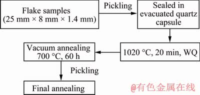
Fig. 1 Preparation procedure of Zr-0.85Sn-0.16Nb- 0.37Fe-0.18Cr specimens with coarse grains
Specimens of 25 mm × 8 mm in size were machined from a 1.4 mm-thick plate of Zr-0.85Sn- 0.16Nb-0.37Fe-0.18Cr alloy. The specimens were sealed in evacuated quartz capsule at about 5×10⁻³ Pa and were heat-treated at 1020 °C (β-phase) for 20 min followed by water quenching and breaking the capsule simultaneously (denoted as β-quenching). After quenching, the specimens were annealed at 700 °C for 60 h firstly, and then were annealed at 580 °C for 5 h. All heat treatments were conducted in a vacuum with 5×10⁻³ Pa, and all specimens were pickled in a mixed acid solution of 30 vol.% H2O + 30 vol.% HNO3 + 30 vol.% H2SO4 + 10 vol.% HF to clean the surface before every heat treatment. The texture and grain size of the samples were analyzed by an Apollo 300 thermal field emission scanning electron microscope equipped with HKL Channel 5 electron back scattering diffraction (EBSD) system, and the step of scanning was 10 μm. The average grain size was about 260 μm (Fig. 2).
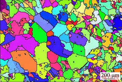
Fig. 2 Electron back scattering diffraction (EBSD) orientation map of Zr-0.85Sn-0.16Nb-0.37Fe-0.18Cr specimen
The specimens were pre-ground, mechanically polished, pickled in 30 vol.% H2O + 30 vol.% HNO3 + 30 vol.% H2SO4 + 10 vol.% HF and cleaned in deionized water. Then, some specimens were corroded in super-heated steam at 500 °C and 10.3 MPa by using a static autoclave. When the temperature reached 150 °C, the DO in water was removed by deaerating, and the DO content was less than 4.5×10⁻⁸ [17], denoted as deaeration condition. Some specimens were corroded in super-heated steam at 500 °C and 10.3 MPa by using a dynamic autoclave with 1×10⁻⁶ DO [12], denoted as DO condition. The DO content in micro-circulation hydrodynamic circuit was controlled by inputting Ar and Ar+O2 gas into water tank alternately. The corrosion tests were conducted in accordance with ASTM G2/G2M-06. The mass gain was the average value of six parallel samples. The corrosion behavior was characterized by measuring the mass gain per unit area. Measured mass gains were fitted to a curve in the form:
wt=10000(Wt-W0)/S (1)
where wt is mass gain at the exposure time of t (mg/dm2); W0 is the mass of sample before corrosion (mg); Wt is the mass of sample at the exposure time of t (mg); S is the superficial area of sample (mm2).
The size and distribution of second phase particles (SPPs) in the alloy before corrosion were examined by the JSM-7500F high resolution scanning electron microscope (HRSEM). The composition and structure of SPPs were analyzed by the JEM-2010F field emission high resolution transmission electron microscopy (HRTEM) equipped with energy dispersive spectrometer (EDS). The fractural, inner and outer surface morphologies of oxide films were observed by JSM-7500F HRSEM. The cross-sectional samples of oxide film for the HRTEM observation were prepared by Helios-600i focused ion beam (FIB). The microstructure of the oxide film was observed by JEM-2010F HRTEM. The crystal structure of SPPs and oxide film was determined by selected area electron diffraction (SAED). High-angle annular dark field (HAADF) images were taken to analyze the morphologies of oxide film in the scanning transmission electron microscopy (STEM) model.
3 Results and discussion
3.1 Microstructure of specimens
Figure 3 shows (0001) pole figure of the Zr-0.85Sn-0.16Nb-0.37Fe-0.18Cr specimens, as well as the inverse pole figures of transverse direction (TD), rolling direction (RD), and rolled plane (ND). The grain surface orientation of the specimens distributes randomly, i.e., there is no obvious texture orientation, which is different from the fine sample with texture. Because the matrix undergoes the phase transformation process of α→β→α after β-quenching, the microstructure with high dislocation density is obtained. Such structure is beneficial to the growth of grain during a long period of annealing, and the texture that exists in the fine crystal sample is completely disrupted.
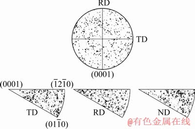
Fig. 3 (0001) pole figure of Zr-0.85Sn-0.16Nb-0.37Fe-0.18Cr specimens and inverse pole figures of transverse direction (TD), rolling direction (RD) and rolled plane (ND) of specimen
Figure 4 shows the microstructure of Zr- 0.85Sn-0.16Nb-0.37Fe-0.18Cr specimens before corrosion. Most SPPs are fine (<200 nm in size) and distribute uniformly, but there are also some coarse SPPs (300-600 nm) distributing along the grain boundaries. According to SAED analysis results, there are Zr(Nb,Fe,Cr)2 SPPs with face centered cube (fcc) and hexagonal close-packed (hcp) structures. These two kinds of SPPs may form at different stages [14]. The coarse SPPs are precipitated during fast-cooling from 1020 °C and then grow in subsequent annealing at 700 °C for 60 h, while the fine SPPs form from the precipitation of alloying elements super-saturated solid solution in α-Zr after annealing at 700 °C for 60 h.
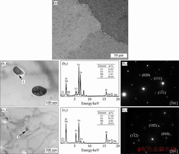
Fig. 4 SEM image of Zr-0.85Sn-0.16Nb-0.37Fe-0.18Cr specimens before corrosion (a); TEM image (b1), EDS (b2) and SAED pattern (b3) of fcc-Zr(Nb,Fe,Cr)2 particle shown by Arrow 1; TEM image (c1), EDS (c2) and SAED pattern (c3) of hcp-Zr(Nb,Fe,Cr)2 particle shown by Arrow 2
3.2 Mass gain
Figure 5 shows the mass gain vs exposure time of Zr-0.85Sn-0.16Nb-0.37Fe-0.18Cr specimens for 500 h exposure in 500 °C and 10.3 MPa super- heated steam under deaeration and DO conditions. The mass gain of the specimens under DO condition is larger than that under deaeration condition. This shows that the high DO content aggravates the corrosion of the alloy.
3.3 Oxide characterization
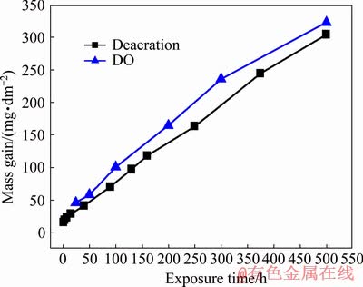
Fig. 5 Mass gain vs exposure time of Zr-0.85Sn- 0.16Nb-0.37Fe-0.18Cr specimens in 500 °C and 10.3 MPa super-heated steam under deaeration and DO conditions
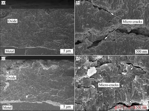
Fig. 6 Fracture morphologies of oxide film forming on Zr-0.85Sn-0.16Nb-0.37Fe-0.18Cr specimens for 500 h exposure in 500 °C and 10.3 MPa super-heated steam under deaeration condition (a, b) and DO condition (c, d)
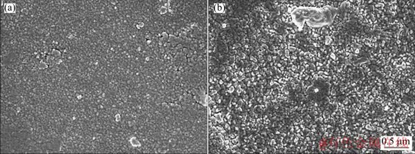
Fig. 7 Outer surface morphologies of oxide film forming on Zr-0.85Sn-0.16Nb-0.37Fe-0.18Cr specimens for 500 h exposure in 500 °C and 10.3 MPa super-heated steam under deaeration condition (a) and DO condition (b)
Figure 6 shows fracture morphologies of the oxide films forming on Zr-0.85Sn-0.16Nb- 0.37Fe-0.18Cr specimens for 500 h exposure in 500 °C and 10.3 MPa super-heated steam under deaeration and DO conditions. The micro-cracks in the oxide films are parallel to the oxide/metal substrate (O/M) interface, and the micro-cracks in the oxide films under DO condition are more than those under deaeration condition. Figure 7 shows the outer surface morphologies of the oxide film forming on Zr-0.85Sn-0.16Nb-0.37Fe-0.18Cr specimens after 500 h exposure in 500 °C and 10.3 MPa super-heated steam under deaeration and DO conditions. Here, outer surface refers to oxide/solution interface. Compared with deaeration condition, the oxide film is looser and the size of ZrO2 grains is a little larger under DO condition. Figure 8 shows inner surface morphologies of the oxide film forming on Zr-0.85Sn-0.16Nb- 0.37Fe-0.18Cr specimens for 500 h exposure in 500 °C and 10.3 MPa super-heated steam under deaeration and DO conditions. Here, inner surface refers O/M interface. Compared with deaeration condition, the inner surface of oxide film is more uneven under DO condition.
The Pilling-Bedworth (P. B.) ratio of Zr oxidized to ZrO2 is 1.56, so the volume expansion occurs during oxidation; Compressive stress parallel to the O/M interface generates in the oxide film, and the tensile stress generates in matrix. In order to reduce the stress at the O/M interface, wavy undulations appear at the O/M interface. Higher DO content accelerates the reaction between oxygen and zirconium, promotes the growth of oxide film, and then leads to the larger amplitude of wavy undulation at the O/M interface. The redistribution of stress due to wavy undulation is the main driving force for the generation of transverse cracks [21,22]. Therefore, the micro- cracks in the oxide films under DO condition are more than those under deaeration condition, and the inner surface of the oxide film is more uneven than that under deaeration condition.
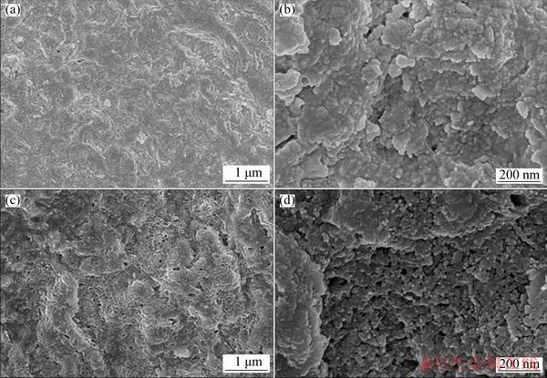
Fig. 8 Inner surface morphologies of oxide film forming on Zr-0.85Sn-0.16Nb-0.37Fe-0.18Cr specimens for 500 h exposure in 500 °C and 10.3 MPa super-heated steam under deaeration condition (a, b) and DO condition (c, d)
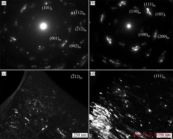
Fig. 9 SAED patterns (a, b) and dark field TEM images (c, d) of oxide layers forming on Zr-0.85Sn-0.16Nb-0.37Fe- 0.18Cr specimens for 24 h exposure in 500 °C and 10.3 MPa super-heated steam under deaeration condition (a, c) and DO condition (b, d)
Figure 9 shows the SAED patterns and micro-structure of the oxide film forming on Zr-0.85Sn-0.16Nb-0.37Fe-0.18Cr specimens for 24 h exposure in 500 °C and 10.3 MPa super-heated steam under deaeration and DO conditions. There are two kinds of ZrO2 with monoclinic (denoted as “m”) and tetragonal (denoted as “t”) structure. For the oxide film forming under deaeration condition, the SAED spots of (002)m, and (101)t planes are strong, while the SAED spots of (001)m and planes are weak. However, for the oxide film forming under DO condition, the SAED spots of (111)m, (200)m and (101)t planes are strong, while the SAED spots of (100)m and (110)m planes are weak. This may have an effect on the corrosion resistance of zirconium alloys.
Figure 10 shows the HAADF images of the cross-sectional oxide film forming on Zr-0.85Sn-0.16Nb-0.37Fe-0.18Cr specimens for 24 h exposure in 500 °C and 10.3 MPa super-heated steam under deaeration and DO conditions. The micro-cracks in the oxide film forming under DO condition are more than those under deaeration condition. This is consistent with the results observed by SEM.
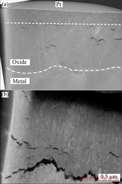
Fig. 10 HAADF images of cross-sectional oxide film forming on Zr-0.85Sn-0.16Nb-0.37Fe-0.18Cr specimens for 24 h exposure in 500 °C and 10.3 MPa super-heated steam under deaeration condition (a) and DO condition (b)
4 Discussion
The oxidation of zirconium-based alloys is viewed as an electrochemical process [23,24]. The oxidation of zirconium alloy occurs at the O/M interface, so the corrosive medium (such as O2- and OH-) needs to transport inward to the O/M interface to further react with Zr matrix. Because the P. B. ratio of zirconium is 1.56, the volume expands during the process of oxidation to generate compressive stress in the oxide film and tensile stress in the matrix. Wavy undulations appear at the O/M interface to reduce the stress of the interface. The redistribution of stress due to wavy undulation is the main driving force for the generation of transverse cracks. Higher DO content leads to accelerated growth of the oxide film and larger wavy undulation at the O/M interface [21,22,25,26]. Therefore, compared with the deaeration condition, the micro-cracks in the oxide films are more and the inner surface of the oxide film is more uneven under DO condition. Higher DO content in the super-heated steam represents higher oxygen potential, which promotes the inward diffusion of oxygen, and accelerates the reaction between oxygen and zirconium, as well as the reaction between oxygen and SPPs at O/M interface. During the oxidation of Zr(Nb,Fe,Cr)2 SPPs, the Zr in Zr(Nb,Fe,Cr)2 occurs to oxidize preferentially, the Fe, Cr and Nb are firstly expelled from Zr(Nb,Fe,Cr)2 SPPs and then are further oxidized to corresponding oxides [27]. The P. B. ratios of Fe oxidized to Fe3O4, Cr oxidized to Cr2O3 and Nb oxidized to Nb2O5 are 2.05, 2.00 and 2.67, respectively [28], so the extra stress is generated around the SPPs during oxidation. And the stress promotes the formation of more pores and cracks, which in turn makes oxygen easier to enter the O/M interface. Therefore, more pores and transverse cracks appear in the oxide film under DO condition, and thus accelerate the corrosion of Zr-0.85Sn- 0.16Nb-0.37Fe-0.18Cr specimen in 500 °C and 10.3 MPa super-heated steam. Obviously, the DO content has an effect on the microstructure and its evolution of the oxide film, thus affecting the corrosion resistance of zirconium alloys.
5 Conclusions
(1) There are Zr(Nb,Fe,Cr)2 SPPs with fcc and hcp structures.
(2) 1×10⁻⁶ DO aggravates the corrosion of the Zr-0.85Sn-0.16Nb-0.37Fe-0.18Cr alloy in 500 °C and 10.3 MPa super-heated steam.
(3) Compared with the deaeration condition, the size of ZrO2 grains and orientation difference between ZrO2 grains become larger, the oxide film is looser and has more micro-cracks, and the internal surface of the oxide film is more uneven under DO condition.
Acknowledgments
The authors would like to express their thanks to Mr. Yu-liang CHU, Mr. Jian-chao PENG, Ms. Xue LIANG, Dr. Peng-fei HU and Dr. Qin BAI of Instrumental Analysis and Research Center of Shanghai University for their assistance in the micro-structural analysis.
References
[1] LIU Jian-zhang. Research trends of dislocation alloys for nuclear power reactors in China [J]. Rare Metal Materials and Engineering, 1990, 6: 32-35. (in Chinese)
[2] MOTTA A T, YILMAZBAYHAN A, GOMES DA SILVA M J, COMSTOCK R J, WAS G S, BUSBY J T, GARTNER E, PENG Q J, JEONG Y H, PARK J Y. Zirconium alloys for supercritical water reactor applications: Challenges and possibilities [J]. Journal of Nuclear Materials, 2007, 371(1-3): 61-75.
[3] LIU Wen-qing, ZHOU Bang-xin, LI Qiang, YAO Mei-yi. Degradation of corrosion resistance of Zircaloy-4 in LiOH aqueous solution [J]. Rare Metals, 2004, 23(3): 286-288.
[4] ZHANG Jin-long, ZHANG Jun, LIANG Nan, ZENG Qi-feng, YUAN Gai-huan, WANG Lian, GAO Bao, YAO Mei-yi, ZHOU Bang-xin. Effect of annealing treatments on corrosion resistance of Zr-Sn-Nb-Fe-Si alloy [J]. The Chinese Journal of Nonferrous Metals, 2017, 27(1): 97-104. (in Chinese)
[5] ZHANG Jin-long, LIANG Nan, ZHAO Han-pei, GOU Shao-qiu, YAO Mei-yi, ZHOU Bang-xin. Effect of Pd addition on corrosion resistance of Zr-4 alloy in LiOH solution [J]. The Chinese Journal of Nonferrous Metals, 2015, 25(3): 675-681. (in Chinese)
[6] YAN Yu-hua, GAO Zu-ying. Development status and characteristics of next generation simplified boiling water reactor (SBWR) [J]. Nuclear Power Engineering, 1997, 18(1): 12-18. (in Chinese)
[7] LIU Xin-rong, CHEN Zhi-qi, HOU Zhong-song. The feature of ABWR and its availability [J]. Shangdong Electric Power Technology, 1996(5): 46-52. (in Chinese)
[8] LIN C C, SMITH F R, ICHIKAWA N, ITOW M. Electrochemical potential measurements under simulated BWR water chemistry conditions [J]. Corrosion, 1992, 48(1): 16-28.
[9] SAVA R L. Modeling of coolant radiolysis in the primary heat transport system of Candu reactors-Effect of coolant boiling [J]. Journal of Nuclear Materials, 1998, 158: 240-252.
[10] SINHA R K, KAKODKAR A. Design and development of the AHWR-The Indian thorium fuelled innovative nuclear reactor [J]. NuclearEngineering andDesign, 2006, 236(7-8): 683-700.
[11] ALLEN T R, KONINGS R J M, MOTTA A T. Corrosion of zirconium alloys [J]. Comprehensive Nuclear Materials, 2012, 5: 49-68.
[12] BRADHURST D H, SHIRVINGTON P J, HEUER P M. The effect of radiation and oxygen on the aqueous oxidation of zirconium and its alloys at 290 °C [J]. Journal of Nuclear Materials, 1973, 46: 53-76.
[13] COX B. Some thoughts on the mechanisms of in-reactor corrosion of zirconium alloys [J]. Journal of Nuclear Materials, 2005, 336(2-3): 331-368.
[14] ZHOU B X, YAO M Y, LI Z K, WANG X M, ZHOU J, LONG C S, LIU Q, LUAN B F. Optimization of N18 zirconium alloy for fuel cladding of water reactors [J]. Journal of Materials Science and Technology, 2012, 28(7): 606-613.
[15] BOJINOV M, KARASTOYANOV V, KINNUNEN P, SAATIO T. Influence of water chemistry on the corrosion mechanism of a zirconium-niobium alloy in simulated light water reactor coolant conditions [J]. Corrosion Science, 2010, 52(1): 54-67.
[16] KUMAR M K, AGGARWAL S, BENIWAL D, DEY A K, SINGH H, KAIN V. Localized oxidation of zirconium alloys in high temperature and pressure oxidizing environments of nuclear reactors [J]. Materials and Corrosion, 2014, 65(3): 244-249.
[17] KUMAR K M, AGGARWAL S, KAIN V, SAARIO T, BOJINOV M. Effect of dissolved oxygen on oxidation and hydrogen pick up behaviour-Zircaloy vs Zr-Nb alloys [J]. Nuclear Engineering and Design, 2010, 240(5): 985-994.
[18] WEI Tian-guo, LIN Jian-kang, LONG Chong-sheng, CHEN Hong-sheng. The Influence of dissolved oxygen in steam on the corrosion behavior of zirconium alloys [J]. Acta Metallurgica Sinica, 2016, 52(2): 209-216. (in Chinese)
[19] COX B. Effects of irradiation on the oxidation of zirconium alloys in high temperature aqueous environments [J]. Journal of Nuclear Materials, 1968, 28: 1-47.
[20] WANG Zhen. TEM study on the initial oxidation behavior of zirconium alloy and its second phase under different hydrochemical conditions [D]. Shanhai: Shanghai University, 2015. (in Chinese)
[21] ZHANG Li-na, CHEN Liang-yu. Review on influencing factors of lateral cracks formation in oxide of zirconium alloys [J]. The Chinese Journal of Nonferrous Metals, 2017, 27(10): 2091-2097. (in Chinese)
[22] LIKHANSKII V, KOLESNIK M. On the evolution of wave structure at the metal/oxide interface during oxidation of Zr alloys [J]. Corrosion Science, 2014, 87: 416-420.
[23] BOJINOV M, CAI W, KINNUNEN P, SAARIO T. Kinetic parameters of the oxidation of zirconium alloys in simulated WWER water-effect of KOH content [J]. Journal of Nuclear Materials, 2008, 378(1): 45-54.
[24] BOJINOV M, HANSSON-LYYRA L, KINNUNEN P, SAARIO T, SIRKIA P. In-situ studies of the oxide film properties on BWR fuel cladding materials [J]. JournalofASTM International, 2005, 2(4): 183-198.
[25] ZHOU Bang-xin, LI Qiang, YAO Mei-yi, LIU Wen-qing, CHU Yu-liang. Effect of water chemistry and composition on microstructural evolution of oxide on Zr alloys [C]//Zirconium in the Nuclear Industry: 15th International Symposium. West Conshohocken, PA: ASTM Special Technical Publication. 2009: 360-383.
[26] PARISE M, SICARDY O, CAILLETAUD G. Modeling of the mechanical behavior of the metal-oxide system during Zr alloy oxidation [J]. Journal of Nuclear Materials, 1998, 256(1): 35-46.
[27] CAO Xiao-xiao, YAO Mei-yi, PENG Jian-chao, ZHOU Bang-xin. Corrosion behavior of Zr(Fex,Cr1-x)2 alloys in 400 °C superheated steam [J]. Acta Metallurgica Sinica, 2011, 47(7): 882-886. (in Chinese)
[28] PROFF C, ABOLHASSANI S, LEMAIGNAN C. Oxidation behaviour of zirconium alloys and their precipitates―A mechanistic study [J]. Journal of Nuclear Materials, 2013, 432(1-3): 222-238.
孙蓉蓉1,徐诗彤1,姚美意1,张 骏1,戴 训2,黄 娇1,张金龙1,周邦新1
1. 上海大学 材料研究所,上海 200072;
2. 中国核动力研究设计院 反应堆燃料及材料重点实验室,成都 610213
摘 要:为了更好地了解溶解氧对锆合金耐腐蚀性能的影响,研究Zr-0.85Sn-0.16Nb-0.37Fe-0.18Cr(质量分数,%)合金在1×10⁻⁶溶解氧和除氧的500 °C和10.3 MPa过热蒸汽中的耐腐蚀性能。利用SEM、TEM、EDS、EBSD研究合金和氧化膜的显微组织。结果表明,高的溶解氧含量会加速合金的腐蚀。与除氧条件相比,在溶解氧条件下氧化膜更疏松且微裂纹更多,氧化膜内表面更加凹凸不平。对于除氧条件下形成的氧化膜,其(002)m、 和(101)t晶面的选区电子衍射斑点较强,而(001)m和
 晶面的选区电子衍射斑点较弱;而在溶解氧条件下形成的氧化膜,其(111)m、(200)m和(101)t晶面的选区电子衍射斑点较强,而 (100)m和(110)m晶面的选区电子衍射斑点较弱。在过热蒸汽条件下较高的溶解氧含量会加速氧化膜的生长,进而降低锆合金的耐腐蚀性能。
关键词:锆合金;溶解氧;腐蚀;显微组织;氧化膜;过热蒸汽
(Edited by Bing YANG)
Foundation item: Projects (51871141, 51471102) supported by the National Natural Science Foundation of China
Corresponding author: Mei-yi YAO; Tel: +86-21-56338586; E-mail: yaomeiyi@shu.edu.cn
DOI: 10.1016/S1003-6326(20)65247-5

