Unmanned wave glider heading model identification and control by artificial fish swarm algorithm
��Դ�ڿ������ϴ�ѧѧ��(Ӣ�İ�)2018���9��
�������ߣ������� ���ڷ� ���� ��ε�� ������
����ҳ�룺2131 - 2142
Key words��unmanned wave glider; artificial fish swarm algorithm; heading model; parameters identification; control parameters optimization
Abstract: We introduce the artificial fish swarm algorithm for heading motion model identification and control parameter optimization problems for the ��Ocean Rambler�� unmanned wave glider (UWG). First, under certain assumptions, the rigid-flexible multi-body system of the UWG was simplified as a rigid system composed of ��thruster + float body��, based on which a planar motion model of the UWG was established. Second, we obtained the model parameters using an empirical method combined with parameter identification, which means that some parameters were estimated by the empirical method. In view of the specificity and importance of the heading control, heading model parameters were identified through the artificial fish swarm algorithm based on tank test data, so that we could take full advantage of the limited trial data to factually describe the dynamic characteristics of the system. Based on the established heading motion model, parameters of the heading S-surface controller were optimized using the artificial fish swarm algorithm. Heading motion comparison and maritime control experiments of the ��Ocean Rambler�� UWG were completed. Tank test results show high precision of heading motion prediction including heading angle and yawing angular velocity. The UWG shows good control performance in tank tests and sea trials. The efficiency of the proposed method is verified.
Cite this article as: WANG Lei-feng, LIAO Yu-lei, LI Ye, ZHANG Wei-xin, PAN Kai-wen. Unmanned wave glider heading model identification and control by artificial fish swarm algorithm [J]. Journal of Central South University, 2018, 25(9): 2131�C2142. DOI: https://doi.org/10.1007/s11771-018-3902-9.

J. Cent. South Univ. (2018) 25: 2131-2142
DOI: https://doi.org/10.1007/s11771-018-3902-9

WANG Lei-feng(���ڷ�), LIAO Yu-lei(������), LI Ye(����), ZHANG Wei-xin(��ε��), PAN Kai-wen(������)
Science and Technology on Underwater Vehicle Laboratory, Harbin Engineering University, Harbin 150001, China
 Central South University Press and Springer-Verlag GmbH Germany, part of Springer Nature 2018
Abstract: We introduce the artificial fish swarm algorithm for heading motion model identification and control parameter optimization problems for the ��Ocean Rambler�� unmanned wave glider (UWG). First, under certain assumptions, the rigid-flexible multi-body system of the UWG was simplified as a rigid system composed of ��thruster + float body��, based on which a planar motion model of the UWG was established. Second, we obtained the model parameters using an empirical method combined with parameter identification, which means that some parameters were estimated by the empirical method. In view of the specificity and importance of the heading control, heading model parameters were identified through the artificial fish swarm algorithm based on tank test data, so that we could take full advantage of the limited trial data to factually describe the dynamic characteristics of the system. Based on the established heading motion model, parameters of the heading S-surface controller were optimized using the artificial fish swarm algorithm. Heading motion comparison and maritime control experiments of the ��Ocean Rambler�� UWG were completed. Tank test results show high precision of heading motion prediction including heading angle and yawing angular velocity. The UWG shows good control performance in tank tests and sea trials. The efficiency of the proposed method is verified.
Key words: unmanned wave glider; artificial fish swarm algorithm; heading model; parameters identification; control parameters optimization
Cite this article as: WANG Lei-feng, LIAO Yu-lei, LI Ye, ZHANG Wei-xin, PAN Kai-wen. Unmanned wave glider heading model identification and control by artificial fish swarm algorithm [J]. Journal of Central South University, 2018, 25(9): 2131�C2142. DOI: https://doi.org/10.1007/s11771-018-3902-9.
1 Introduction
Traditional motion monitoring platforms use fuel oil or batteries as power sources; therefore, their endurance is limited by the energy capacity of the power source. This strategy consumes excessive time and resources, and may also bring pollution to the environment. However, there are abundant green energy resources in the oceans. In recent years, an increasing number of researchers have focused on the use of ocean energy as the power source for ocean vehicles. There have been many studies on ocean energy powered unmanned vehicles [1], mainly solar-powered underwater vehicles [2], thermal-powered underwater vehicles [3], wind-powered or solar-powered unmanned surface vehicles [4, 5], and wave-powered vehicles. The unmanned wave glider (UWG) is a new kind of wave-powered unmanned ocean vehicle, which has many outstanding advantages like infinite endurance, autonomy, zero discharge, and low cost. In recent years, UWGs have been widely applied in multiple marine scientific research and survey activities [6�C12].
The motion control problem is one of the main challenges for unmanned vehicles. Many researchers have made great contributions [13, 14]. However, the unusual structure and unique under- actuated characteristics make UWG��s motion modeling and the motion control problem specially challenging.
The UWG consists of a surface float (Float), a submerged glider (Wave thruster, or Glider) and a flexible umbilical. The special structure is very different from structures of traditional marine vehicles. On the one hand, the UWG has a multi- body property. The UWG contains a rigid body and a flexible body, which is a special kind of rigid-flexible multi-body system; on the other hand, the UWG belongs to marine vehicles, which are subject to environmental forces mainly acting on the float when the UWG is sailing in seas, thus classifying the UWG as a special marine vehicle. Currently, correlational researches mainly concentrate on two aspects: speed predicting and maneuverability modeling and analysis.
SMITH et al [15] discussed online speed predicting of a UWG to provide a dynamic model of accurate speed estimation for offline route planning. The purpose is to further improve the system��s control performance. NGO et al [16, 17] established a nonlinear, random, and nonparametric speed predicting model and identified the model parameters based on a GAUSSIAN process regression method. By comparison with sea trial results, the method proved effective in predicting UWG��s speed. TIAN et al [18] established a UWG��s dynamic model in a longitudinal profile based on a D-H approach. Simulations under different sea states were completed. Simulation results show that the dynamic model in a longitudinal profile reflects the longitudinal motion process to a certain extent. However, it is not helpful in heading control problems.
LIAO et al [19] designed an embedded control system. An improved S-surface control method based on rudder angle compensation was proposed, which can compensate for the adverse effects from environmental forces and installation error. However, parameters of the control system need artificial setting.
The special system characteristics of the UWG bring huge difficulties to the dynamic analysis. There is not an accepted and mature maneuverability model and analysis method both at home and abroad. There are mainly two kinds of solutions: 1) Ship��s maneuverability theory. The degrees of each part of the UWG are treated differently. Major degrees, which influence the system deeply, are chosen and minor degrees, which have less influence, are ignored. After degree reduction, it is convenient to apply maneuvering theory of marine vehicles to analyze a UWG��s dynamic model [20�C22]. 2) Multi-body dynamics theory. To simplify the dynamic analysis, the umbilical is assumed to be rigid since the umbilical is almost always in tension. Under this assumption, the UWG was simplified as a rigidly connected multi-body system or a rigid double�Cbody structure, which lays the foundation of multi-body analysis [23�C25]. Heading control is the basis for the UWG to realize autonomous navigation. However, we cannot obtain the heading motion response equation using existing maneuverability modeling and predicting methods of the UWG or the model precision cannot satisfy control requirements. In this paper, UWG��s heading motion model identification and control parameters optimization methods based on trial data will be discussed.
This work focuses on the ��Ocean Rambler�� UWG, on which the heading motion model identification and control parameters optimization problems were studied. First, under certain assumptions, we established the planar motion model of the float body; subsequently, on the basis of trial data, the parameters of the heading motion model were identified using the artificial fish swarm algorithm, and control parameters were intelligently optimized. Finally, the UWG��s tank tests and sea trials of the heading control were carried out.
2 Motion mathematical modeling of UWG
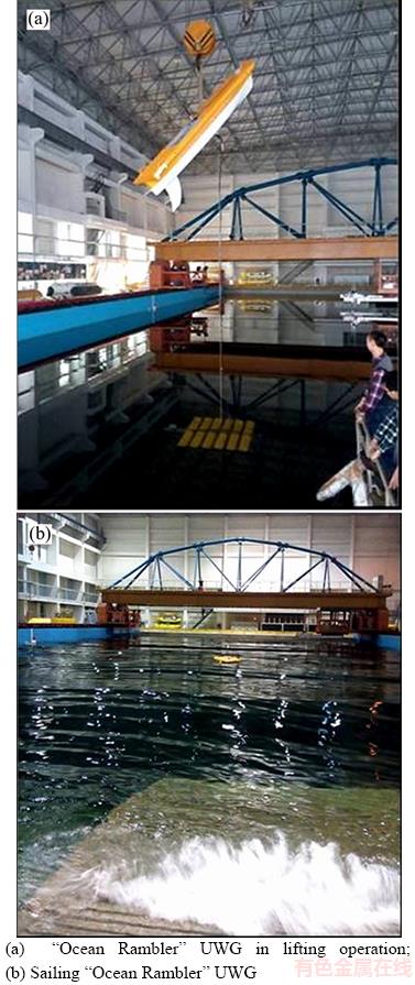
Since 2012, the Science and Technology on Underwater Vehicle Laboratory of Harbin Engineering University, China has carried out research on UWG, firstly in China. Two types of prototypes ��Ocean Rambler I�� and ��Ocean Rambler�� (Figure 1(a)) have been built. Several standard tank tests and sea trials have been completed.

Figure 1 ��Ocean Rambler�� UWG (a) and operating principle (b)
The UWG consists of a surface float (Float), a submerged glider (Wave thruster, or Glider) and a flexible umbilical. Several wings are hinged on the glider. The Glider provides thrust for the UWG. In a wave environment, when the float moves down a wave, the glider falls under its own weight, and the aft of wings rise. Conversely, when the float is pulled upward by a wave, the umbilical lifts the glider and the aft of wings fall. The wings fall and rise alternately like a fish that pushes the glider forward. In addition, the float is pulled forward by the umbilical. The operating principle is shown in Figure 1(b). The UWG mechanically converts the wave energy to thrust, and other motive powers are unnecessary.
2.1 Motion mathematical model
The float of UWG is a mini ship. Considering the needs of the study, we made the following assumptions:
1) The float is symmetrical about the longitudinal section in the center plane. Only the motions in planar ��=[x y ��]T, ��=[u �� r]T are considered, and the influences of roll, pitch, and heave motions are ignored.
2) The umbilical is rigid, which implies that the glider��s heading and the float��s heading are consistent; the glider is simplified as a usual thruster, which means that the glider only translates longitudinal thrust Fu and yawing moment Tr to the float. The weights of the umbilical and the glider are considered to be converged on the float. The other influences on the planar motion of the float of the umbilical and glider are ignored.
Under the above-mentioned assumptions, the motion of the UWG was simplified to the planar motion of the float as shown in Figure 2.

Figure 2 Planar motion model of UWG
Based on Ship��s maneuverability theory [26], we can obtain the motion mathematical model of the UWG in the horizontal plane:
 (1)
(1)
The speed of the UWG depends on the wave environment, which is random and uncontrollable. However, the average speed in a certain sea state is relatively stable. Therefore, we assume that the longitudinal velocity changes slightly in a certain sea state, which always holds 
 where U equals the average velocity in different sea states
  . Considering the low speed of the UWG, we choose the first order nonlinear K-T equation to describe the yawing motion [26]. The motion mathematical model of UWG in the horizontal plane can be expressed as:
 (2)
(2)
where ��=[x y ��]T are longitudinal displacement, transverse displacement, and heading angle, respectively; ��=[u �� r]T are longitudinal velocity, transverse velocity, and yawing angular velocity, respectively; �� is the actual rudder angle; m11, m22, Y�� are inertial masses and damping force calculated by the following:
 where m is the mass; T is the turning lag index, which is a time constant; K is the turning ability index; and �� is the coefficient of the model��s nonlinear term, namely NORBBIN coefficient.
2.2 Estimation of hydrodynamic parameters
The above-mentioned maneuvering parameters can be obtained by maneuvering trials in tank and sea, or by hydrodynamic calculation using empirical formulas. Restricted by experimental conditions and funds, only parts of maneuvering tests were carried out at the beginning of the study. Because of the lack of maneuvering test data of the prototype, parameters like and
and were estimated using empirical formulas. However, parameters about heading motion like K, T and �� were expected to be identified based on tank test data.
 was calculated using ZHOU��s regression formula [27], and
  andwere calculated using the regression formula of linear hydrodynamic parameters proposed by CLARKE et al [28]. These regression formulas are summarized through a large number of experiments; hence, they have good applicability.


 (3)
(3)
whereandcan be estimated using the regression formula (3); K, T and �� are expected to be identified using the artificial fish swarm algorithm based on tank test data. The identifying process is elaborated below. L, B, D and Cb are length, beam, draft, and block coefficients of the float, respectively; �� and U are the water density and the speed, respectively. The main parameters of the ��Ocean Rambler�� UWG are shown in Table 1.
Table 1 Main parameters of Ocean Rambler UWG

3 Artificial fish swarm algorithm
The heading motion of ships, warships, or UWGs is a kind of typical nonlinear system whose motion model identification is a typical optimal parameter identification problem of nonlinear systems. The intelligent optimization algorithms are widely applied in numerical calculation, autonomous control, robotics, image processing, machine learning, data mining, etc. [29]. Commonly used intelligent optimization algorithms include: ant colony optimization algorithm (ACO), particle swarm optimization algorithm (PSO), genetic algorithm (GA), and artificial fish swarm algorithm (AFSA).
The artificial fish swarm algorithm (AFSA) is a kind of bionic swarm intelligence algorithm proposed by LI [30] in 2002. It is based on the concept of animats. It realizes swarm intelligence by simulating cruising and foraging behaviors of fish shoals in nature (mainly including preying, swarm, following, and random phenomena), creating the individual underlying behavior, and simulating the cooperative behavior of fish. The algorithm is widely applied in control parameters tuning [30], model identification [31], data mining [32], and network communication optimization areas [33].
Here is a brief introduction of AFSA. For more details, see Ref. [30]. Related concepts and parameter definitions: Degree is the maximum dimension of search space, namely the number of optimal variables, or D for short; Bd is the solution domain of optimal variables, namely Bd=[Bdi/min Bdi/max], (i=1, 2, D); Vs is the vision, or so called apperceive scope of artificial fish. St is the maximum step length of artificial fish; �� is the congestion coefficient, which represents the aggregation degree of the fish shoal; Tn is tentative times; AF number is the total number of artificial fish shoals, or n for short; X represents the whole artificial fish shoal as X=[ X1, X2, ��, Xn]T; the state of the ith artificial fish individual is represented as Xi=(Xi1, Xi2, ��, XiD), (i=1, 2, ��, n); the distance between artificial fish individuals is represented as  food concentration of the current position of the artificial fish of sequence i is represented as Yi=f(Xi); Y is the objective function value; Time is the maximum iterative number, or Kmax for short; k means the kth iteration. Mutual transformation between a maximization problem and a minimization problem is easy, and the maximization problem will be taken as an example to be discussed in this paper.
3.1 Behavior description
1) AF_prey
Let the current state of the artificial fish be Xi. Select a state randomly in within the view of the artificial fish (namely di,j��Vs). If the corresponding food concentration Yi
 (4)
(4)
where Yi is the food concentration of state Xi; Xi/next is the next state of the artificial fish of sequence i; Random(St) is the random number within [0, St];  is the distance between artificial fish individuals. The symbol definitions in subsequent formulas are the same as what we have explained here.
2) AF_swarm
Let the current state of the artificial fish be Xi. Search the number of partners nf and the central location Xc in its neighborhood (di,j��Vs). If the corresponding food concentration Yc/nf >��Yi, which means the central location of the partners has higher food concentration and is not crowded, move to the direction Xc one step; otherwise, take the preying behavior which is defined as the default behavior.
 (5)
(5)
For the special case when there is not any partner in the searching neighborhood, take the preying behavior acquiescently.
3) AF_follow
Let the current state of the artificial fish be Xi. Search for the optimal neighbor Xmax in its neighborhood (di,j��Vs), which has the maximum food concentration Ymax. If Ymax>Yi and  in which nmax/f is the number of partners in the neighborhood of Xmax (it means that the location of partner Xmax has higher food concentration and is not crowded), move to the direction Xmax one step; otherwise, take the preying behavior, which is defined as default behavior.
 (6)
(6)
If there is not any partner in the searching neighborhood, take the preying behavior acquiescently.
4) AF_random
Random behavior means that the artificial fish selects a state randomly and moves to that direction. The purpose is to search for food or partners in a wider sense. The random behavior is the default mode of the preying behavior.
5) AF_strategy
For solving different problems, we need to evaluate the current environment of the artificial fish to choose the behavior strategy. Commonly used behavior strategies include: principle of optimal progress��choose the behavior that makes the next state of the artificial fish optimal; principle of progress��choose one behavior or a combination of multiple behaviors as long as there is any progress. If there is not any progress using the aforementioned strategies, take random behavior.
6) AF_bulletin
Set up a bulletin board to record the state of the optimal individual in the artificial fish shoal and the food concentration of the optimal individual��s location. Every artificial fish will compare the state of itself with the states on the bulletin board after an action. If the state of itself is more optimal, update the bulletin board state using one��s state. It is always the optimal state in the history of the bulletin board.
3.2 Algorithm procedure
Based on the above AFSA behaviors, we provide the basic procedure of the algorithm as follows:
The first step: setup proper parameters D, Bd, Vs, St, n, Kmax, Tn and �� of the artificial fish shoal according to the specific problem. Initialize the artificial fish shoal. Search for the optimal artificial fish and record the state onto the bulletin board. Set the iteration times k to zero.
The second step: take the iteration of k+1 times. Evaluate the optimization process and choose the behavior strategy.
The third step: according to the behavior strategy, each artificial fish implements behaviors like preying, swarming, and following. Evaluate the individuals, and if an artificial fish��s state is better than that on the bulletin board, update the bulletin board state using the artificial fish��s state.
The fourth step: judge whether it meets the exit condition. The exit conditions can be reached the maximum iteration times, satisfying optimization precision, or no progress after iterating for several times. In this study, the exit condition is the maximum iteration times. If k=Kmax, the algorithm exits; otherwise, go to the second step.
3.3 Analysis of artificial fish swarm algorithm
A large number of researches and applications show that the AFSA is a good solution for optimization of nonlinear functions [30�C33]. The main advantages of AFSA:
1) It has good ability to avoid local extrema and obtain the global extremum. In addition, it has a certain degree of adaptability;
2) Only the value of the target function needs to be compared and specific information, like gradients, is not necessary. Therefore, this algorithm has a low requirement of properties for the target function.
3) The algorithm has a low requirement of the initial value, which can be a random value or a fixed value. In addition, it is less sensitive to parameters;
4) The algorithm has the ability of parallel optimization and converges fast.
4 Identification of heading motion parameters and analysis
4.1 Identification of heading model parameters based on AFSA
In 2014, the ��Ocean Rambler�� completed tank tests including a straight test, a turning test, and a heading control test. The dimensions of the test tank are 50 m��30 m��10 m; automatic control system was deployed on the UWG in tank tests; the heading angle was measured by a TCM compass, and the actual rudder angle was the feedback value from the encoder of the micro steering gear. The UWG was also equipped with an integrated weather station, which supplied GPS information and velocity information. A regular wave measures 0.23 m in height and 10 m in length. There is no current in tank tests.
The average velocity measured by the integrated weather station was about 0.4 m/s in tank tests. The size of the tank is known, and the time elapsed for the UWG to sail from one side of the tank to the other can be recorded by timer. The velocity thus can be estimated as the length of the tank divided by the time elapsed. The estimated velocity was close to the measured velocity in the tank test, which verifies the accuracy of the measured velocity. According to GPS information from the integrated weather station, we can draw the trajectory of the UWG. The turning radius was estimated from the trajectory. The wave glider faced beam waves and longitudinal waves when turning for 360�� in the turning test. The hydrodynamic performance and turning performance are different in beam waves and longitudinal waves; therefore, the trajectory is not a standard circle. The UWG��s turning radius with a rudder angle of 30�� was about 20�C30 m. The turning radius is an estimated value, which is not really precise, but it does not influence the heading model identification and control parameters optimization. Figure 3 shows the tank tests.
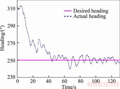
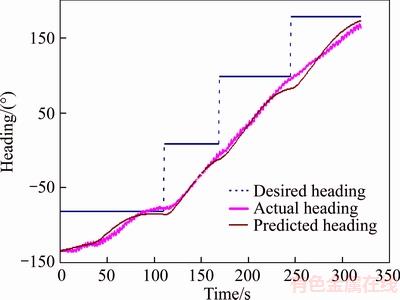
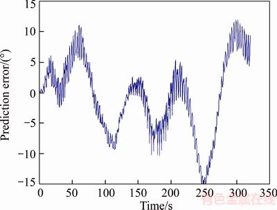
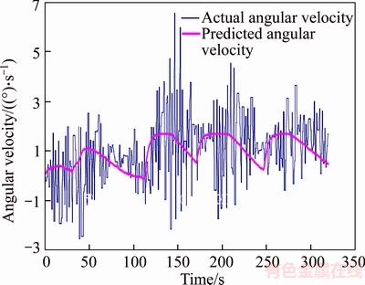
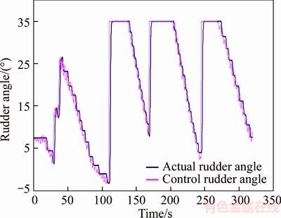
Next, we identified the parameters of the heading motion using AFSA based on heading control test data in tank. As a matter of experience, we set the range of model parameters 0 Finally, the model parameters of the heading motion of the ��Ocean Rambler�� UWG at the velocity of 0.4 m/s were identified as K=0.049, T=4, ��=17. To verify the efficiency of the algorithm, numerical prediction of the heading motion based on the identified parameters was completed. Comparison between numerical prediction and trial results is shown in Figures 4�C7. Figure 3 Ocean Rambler UWG in tank tests: Figure 4 Contrast curve of heading angle Figure 5 Prediction error of heading angle In Figure 4, the blue dotted line represents the desired heading. The pink line represents the actual heading. The brown line represents the predicted heading. The actual heading is trying to follow the desired heading. In general, the predicted heading is close to the actual heading. Figure 5 shows the error between actual heading and predicted heading. From Figures 4 and 5, the prediction of heading angle can be realized using the identified model parameters. The prediction error of the heading angle is �C0.6�� in average and is almost within ��10��; when the rudder angle changes suddenly, the prediction error is larger, but the predicting value approaches the actual heading angle rapidly.Figure 6 shows the actual angular velocity and the predicted angular velocity. From Figures 4 and 6, caused by environmental disturbance and measurement noise of magnetic compass, the actual heading angle and yawing angular velocity measurements showed great fluctuation and considerable oscillation, which is harmful to the heading control performance. However, the predicting heading angle and yawing angular velocity using identified model parameters appeared smooth and without fluctuation, which is beneficial for further increasing the heading control precision. In Figure 7, the blue line represents the actual rudder angle. The pink line represents the control rudder angle. Obviously, there must be a lag between the actual and control rudder angles. However, from Figure 7, the steering engine responded quickly and is with great control accuracy, satisfying for the requirement of the tank test. Figure 6 Contrast curve of yawing angle velocity Figure 7 Contrast curve of rudder angle 4.2 Maneuverability parameter estimation at typical speeds Parameters identified by test data are more precise than those calculated by the theory of similarity. However, test data is not enough in different conditions because of limited test time and limited funds. As to the UWG, the velocity is low and has a small difference in different sea states (0�C3 kn). Therefore, according to the theory of similarity, the maneuverability parameters K, T, �� at a velocity of 0.4 m/s can be used to calculate the maneuverability parameters at other velocities. In order to take full advantage of the limited trial data to factually describe dynamic characteristics of the system, maneuverability parameters under other conditions were calculated by the theory of similarity. First, we calculated the dimensionless maneuverability parameters of the ��Ocean Rambler�� UWG at a velocity of 0.4 m/s. Then, the maneuverability parameters at some typical velocities were estimated. The calculating results are shown in Table 2. where K��, T��, ���� are dimensionless maneuverability parameters. Table 2 Maneuverability parameters at some typical velocities 5 Control parameters optimization and experiments We applied the S-surface controller [34] in the heading control of the ��Ocean Rambler�� UWG. Below, we discuss the intelligent optimization of control parameters. 5.1 S-surface controller The function of the S-surface controller is: where e and Only heading control of UWG will be discussed because the speed is uncontrollable. The control parameters to be optimized are k��1 and k��2. Although the S-surface controller has few parameters to be optimized, there are still some problems in the application of time-consuming and difficult to obtain optimal performance. It is expected to save valuable test time if the existing mathematical model is applied to optimize the control parameters to promote engineering applications. In the optimization process of control parameters, it is often necessary to discontinuously search for a wide range. In view of the strong adaptability and global search capability of AFSA, the control parameters of wave glider are optimized based on AFSA. 5.2 Selection of objective function and fish shoal parameters The purpose of the controller design is to minimize the control system��s performance index function J. The commonly used evaluation index in system design is As a matter of experience, we set the range of control parameters 0 Finally, the parameters of the heading controller were identified as k��1=40, k��2=0.3. 5.3 Trial results and analysis In 2015-2016, the ��Ocean Rambler�� UWG completed a series of sea trials in Shandong waters, as shown in Figure 8. Figures 9 and 10 show the heading control results in tank tests and sea trials. Both in Figures 9 and 10, the pink lines represent the desired heading and the blue dashed line the actual heading. From Figures 9 and 10, the heading of UWG outputs smoothly with fast convergence and no overshoot. The steady-state heading error is ��3�� in tank tests and ��8�� in sea trials. In sea trials, the velocity of the ��Ocean Rambler�� UWG is about 1.5�C2.1 kn in good environmental conditions. Compared to traditional marine unmanned vehicles like AUV and USV (velocity ��3 kn), the velocity of UWG is lower, which causes bad steerage, so the heading control ability and the heading control accuracy of UWG are weaker than in traditional marine unmanned vehicles. The UWG is designed for large-scale marine environment monitoring. The precision requirement of the target area is in the kilometer class. A small heading error may cause some path following error or waypoint tracking error, but these kinds of errors are acceptable in large-scale marine environment monitoring. Therefore, the heading control accuracy of the ��Ocean Rambler�� UWG meets its application requirements. Figure 8 Ocean Rambler UWG in sea trials Figure 9 Heading control results in tank tests Figure 10 Heading control results in sea trials Compared to the experimental environment in tank, the marine environment interferes with the UWG more significantly, which causes the worse control performance in sea trials than in tank tests, especially as output oscillation. From the results in tank tests and sea trials, it can be seen that the control parameters obtained by the AFSA optimization method can ensure that the UWG converges to the desired value rapidly and has good control performance, which effectively achieves the heading control task. 6 Conclusions 1) Under some assumptions, the rigid-flexible multi-body system of the UWG was simplified as a rigid system composed of ��thruster + float body,�� based on the planar motion model on which the UWG was established. Some model parameters were estimated using the empirical method. 2) Aiming at the parameter identification of the heading model of the UWG, the AFSA method was introduced, and the UWG��s heading motion model parameters were identified using the tank test data. Based on the established heading motion model, the parameters of the heading controller were optimized by AFSA. 3) Contrast of heading motion of the ��Ocean Rambler�� UWG and control experiments were completed in tank and sea trials. Trial results verify the effectiveness of used method. It lays the foundation for further improvement of the simulation platform and the autonomous control research of UWG. References [1] WANG Xiao-ming, SHANG Jian-zhong, LUO Zi-rong, TANG Li, ZHANG Xiang-po, LI Juan. Reviews of power systems and environmental energy conversion for unmanned underwater vehicles [J]. Renewable and Sustainable Energy Reviews, 2012, 16(4): 1958�C1970. DOI: 10.1016/j.rser. 2011.12.016. [2] HU Yu-li, WANG Jia-jun. Study on power generation and energy storage system of a solar powered autonomous underwater vehicle (SAUV) [J]. Energy Rocedia, 2012, 16: 2049�C2053. DOI: 10.1016/j.egypro.2012.01.311. [3] MA Zhe-song, LIU Yu-hong, WANG Yan-hui, WANG Shu-xin. Improvement of working pattern for thermal underwater glider [C]// Oceans2016. Shanghai, China: IEEE, 2016: 1�C6. DOI: 10.1109/OCEANSAP.2016.7485404. [4] HOOK D, DALTRY R, COELHO R. C-enduro USV developed for offshore long-endurance applications [J]. Sea Technology, 2014, 55(3): 15. [5] PLUMET F, PETRES C, ROMERO-RAMIREZ M A, GAS B, LENG S H. Toward an autonomous sailing boat [J]. IEEE Journal of Oceanic Engineering, 2015, 40(2): 397�C407. DOI: 10.1109/JOE.2014.2321714. [6] LIAO Yu-lei, LI Ye, LIU Tao, LI Yi-ming, WANG Lei-feng, JIANG Quan-quan. Unmanned wave glider technology: State of the art and perspective [J]. Journal of Harbin Engineering University, 2016, 37(9): 1227�C1236. DOI: 10.11990/jheu. 201603099. (in Chinese) [7] BENSON M A, LECOQ T, MERCADO G, NAKAYAMA S, MOLDOVEANU N, CAPRIOLI P, NYEIN G, PAI S, YANDON E. Acquisition using autonomous marine vehicles: Wave glider field test, offshore Abu Dhabi [C]// SPE Middle East Oil & Gas Show and Conference. Manama, Bahrain: Society of Petroleum Engineering, 2017: 6�C9. DOI: https://doi.org/ 10.2118/183869-MS. [8] LIAO Yu-lei, WANG Lei-feng, LI Ye, LI Yi-ming, JIANG Quan-quan. The intelligent control system for an unmanned wave glider [J]. PlosOne, 2016, 11(12): e0168792. DOI: 10.1371/journal.pone.0168792. [9] HERMSDORFER K, WANG Q, LIND RJ, YAMAGUCHI R T, KALOGIROS J. Autonomous wave gliders for air-sea interaction research [C]// The 19th Conference on Air-Sea Interaction. Phoenix, USA, 2015: 25�C31. http://ams. confex.com/ ams/95Annual/webprogram/Paper268202.html. [10] XU Chun-ying, CHEN Jia-wang, ZHENG Bing-huan. Research status and applications of wave glider [J]. Journal of Ocean Technology, 2014, 33(2): 111�C117. (in Chinese) [11] GOEBEL N L, FROLOV S, EDWARDS C A. Complementary use of wave glider and satellite measurements: Description of spatial decorrelation scales in Chl-a fluorescence across the pacific basin [J]. Methods in Oceanography, 2014, 10: 90�C103. DOI: http://dx.doi.org/ 10.1016/j.mio.2014.07.001. [12] van LANKER V, BAEYE M. Wave glider monitoring of sediment transport and dredge plumes in a shallow marine sandbank environment [J]. PlosOne, 2015, 10(6): e0128948. 1�C19. DOI: 10.1371/ journal.pone.0128948. [13] JIANG Chun-meng, WAN Lei, SUN Yu-shan. Design of motion control system of pipeline detection AUV [J]. Journal of Central South University, 2017, 24(3): 637�C646. DOI: 10.1007/s11771-017-3464-2. [14] TAN Pan-long, SUN Qing-lin, JIANG Yu-xin, ZHU Er-lin, CHEN Zeng-qiang, HE Ying-ping. Trajectory tracking of powered parafoil based on characteristic model based all-coefficient adaptive control [J]. Journal of Central South University, 2017, 24(5): 1073-1081. DOI: 10.1007/s11771- 017-3510-0. [15] SMITH R N, DAS J, HINE G, ANDERSON W, SUKHATME G S. Predicting wave glider speed from environmental measurements [C]// Oceans2011. Kona, USA: IEEE/MTS, 2011: 1�C8. DOI: 10.23919/OCEANS.2011. 6106989. [16] NGO P, AL-SABBANA W, THOMAS J, ANDERSON W, DAS J, SMITH R N. An analysis of regression models for predicting the speed of a wave glider autonomous surface vehicle [C]// Australasian Conference on Robotics and Automation. Sydney, Australia: University of New South Wales, 2013: 1�C9. www.araa.asn.au/acra/acra2013/papers/ pap151s1-file1.pdf. [17] NGO P, DAS J, OGLE J, THOMAS J, ANDERSON W, SMITH R N. Predicting the speed of a wave glider autonomous surface vehicle from wave model data [C]// IEEE/RSJ International Conference on Intelligent Robots and Systems(IROS2014). Chicago, USA: IEEE/RSJ, 2014: 2250�C2256. DOI: 10.1109/IROS.2014.6942866. [18] TIAN Bao-qiang, YU Jian-cheng, ZHANG Ai-qun. Dynamic modeling of wave driven unmanned surface vehicle in longitudinal profile based on D-H approach [J]. Journal of Central South University, 2015, 22(12): 4578�C4584. DOI: 10.1007/s11771-015- 3008-6. [19] LIAO Yu-lei, LI Yi-ming, WANG Lei-feng, LI Ye, JIANG Quan-quan. Heading control method and experiments for an unmanned wave glider [J]. Journal of Central South University, 2017, 24(11): 2504�C2512. DOI: https://doi.org/ 10.1007/s11771-017-3663-x. [20] KRAUS N D, BINGHAM B. Estimation of wave glider dynamics for precise positioning [C]// Oceans2011. Kona, USA: IEEE/MTS, 2011: 1�C9. DOI: 10.23919/ OCEANS.2011.6107207. [21] KRAUS N D. Wave glider dynamic modeling, parameter identification and simulation [D]. Hawaii, USA: University of Hawaii, 2012. [22] LU Xu. Research on the general technology of wave glider [D]. Harbin, China: Harbin Engineering University, 2015. (in Chinese) [23] LI Xiao-tao. Dynamic model and simulation study based on the wave glider [D]. Beijing, China: China Ship Research and Development Academy, 2014. (in Chinese) [24] QI Zhan-feng, LIU Wen-xia, JIA Li-yuan, QIN Yu-feng, SUN Xiu-jun. Dynamic modeling and motion simulation for wave glider [J]. Applied Mechanics and Materials, 2013, 397�C400: 285�C290. DOI: 10.4028/www.scientific.net/AMM. 397-400. 285. [25] JIA Li-yuan. Study of operation principle of two-part architecture and dynamic behavior of wave glider [D]. Tianjin, China: National Ocean Technology Center, 2014. (in Chinese) [26] FOSSEN T I. Handbook of marine craft hydrodynamics and motion control First Edition [M]. Chichester: John Wiley & Sons Ltd, 2011. [27] ZHOU Zhao-ming, SHENG Zi-yin, FENG Wu-shi. Maneuverability prediction and calculation of multi-purpose cargo vessels [J]. Ship Engineering, 1983(6): 21�C29, 36. (in Chinese) [28] CLARKE D, GEDLING P, HINE G. The application of manoeuvring criteria in hull design using linear theory [J]. Naval Architect, 1983, 125: 45�C68. [29] SHEN Wei, GUO Xiao-pen, WU Chao, WU De-sheng. Forecasting stock indices using radial basis function neural networks optimized by artificial fish swarm algorithm [J]. Knowledge-Based Systems, 2011, 24(3): 378�C385. DOI: 10.1016/ j.knosys.2010.11.001. [30] LI Xiao-lei. A new intelligent optimization method-artificial fish swarm algorithm [D]. Hangzhou, China: Zhejiang University, 2003. (in Chinese) [31] HU Gui-bing, QIU Xue-song, MENG Luo-ming. Radio frequency identification network planning for indoor localization based on enhanced artificial fish swarm algorithm [J]. Journal of Computational & Theoretical Nanoscience, 2016, 13(11): 8963�C8969. DOI: 10.1166/jctn. 2016.6071. [32] BHARATHI T, KRISHNAKUMARI P. Application of modified artificial fish swarm algorithm for optimizing association rule mining [J]. Technology & Indian Journal of Science, 2014, 7(12): 1906�C1915. http://www.indjst.org/ index.php/indjst/article/view/46852. [33] WU Hua-feng, CHEN Xin-qiang, SHI Chao-jian, XU Ming. An ACOA-AFSA fusion routing algorithm for underwater wireless sensor network [J]. International Journal of Distributed Sensor Networks, 2012, 8(5): 1-9. DOI: 10.1155/ 2012/920505. [34] LIAO Yu-lei, WAN Lei, ZHUANG Jia-yuan. The embedded motion control system for the water-jet-propelled unmanned surface vehicle [J]. Chinese High Technology Letters, 2012, 22(4): 416-422. DOI: 10.3772/j.issn.1002-0470.2012.04.013. (in Chinese) (Edited by FANG Jing-hua) ���ĵ��� �����˹���Ⱥ�㷨�IJ��˻���������ģ�ͱ�ʶ����� ժҪ����ԡ����������ߡ��Ų��˻������������˶�ģ�ͱ�ʶ�����Ʋ����Ż����⣬�����˹���Ⱥ�㷨������Ӧ���ڲ��˻���������ģ�Ͳ�����ʶ�Ϳ����С����ȣ��ڼ��������£������˻������Ӹ������ϵͳ��Ϊһ�����ƽ���+���塱����ϵͳ�����������˲��˻�����ˮƽ���˶���ѧģ�ͣ�Ȼ��ȡ���鷽����ϲ�����ʶ�IJ��Ի�ȡ��ģ�Ͳ�����������ģ�Ͳ����ɾ��鷽������õ������Ǽ���������Ƶ������Ժ���Ҫ�ԣ�����ģ�Ͳ�������ˮ���������ݲ������˹���Ⱥ�㷨���б�ʶ��ã��Ӷ���ֵ���������������������ʵ�̻�ϵͳ�Ķ���ѧ���ԡ���Ը������˶�ģ�ͣ������˹���Ⱥ�㷨��������S��������IJ����Ż�����ɡ����������ߡ��Ų��˻�����������Ԥ���Աȼ����Ͽ������顣ˮ��������֤�������˶�ģ�Ͳ��˻����������˶���Ԥ����нϸߵľ��ȣ���������Ǻ�ת�����ٶȡ���ˮ������ͺ��������в��˻�������չ���˽Ϻõ�����������ܣ���������֤���������������Ч�ԡ� �ؼ��ʣ����˻��������˹���Ⱥ�㷨������ģ�ͣ�������ʶ�����Ʋ����Ż� Foundation item: Project(51779052) supported by the National Natural Science Foundation of China; Project(QC2016062) supported by the Natural Science Foundation of Heilongjiang Province, China; Project(614221503091701) supported by the Research Fund from Science and Technology on Underwater Vehicle Laboratory, China; Project(LBH-Q17046) supported by the Heilongjiang Postdoctoral Funds for Scientific Research Initiation, China; Project(HEUCFP201741) supported by the Fundamental Research Funds for the Central Universities, China Received date: 2017-04-14; Accepted date: 2018-01-15 Corresponding author: LIAO Yu-lei, PhD, Associate Professor; Tel: +86�C18045623860; E-mail: liaoyulei_work@163.com, liaoyulei@hrbeu.edu.cn; ORCID: 0000-0003-3530-9529
 (7)
(7)
 (8)
(8) are control inputs (normalized error and error rate respectively); u is the normalized control force output; k1 and k2 are the control parameters corresponding to error and error rate respectively, and that can influence the rate of change of the corresponding control inputs. Obviously, compared to PID, sliding mode control and backstepping methods, the S-surface controller has a more concise structure and less parameters.
 , where �� is error (for example,
  in heading control, in which ��d, �� are the desired and actual headings, respectively). ITAE emphasizes the overshoot and adjustment time while not the initial error. It comprehensively reflects the speed and accuracy of the control system and is widely used in the control field. Taking the objective function as the countdown of J(ITAE), that is Y=1/J(ITAE). The control parameters optimization is transformed into searching the maximum value of the objective function Y.