J. Cent. South Univ. (2012) 19: 1399-1410
DOI: 10.1007/s11771-012-1156-5
Dynamic analysis of dam-reservoir-foundation interaction using
finite difference technique
M. Abdollahi, R. Attarnejad
School of Civil Engineering, University of Tehran, Tehran, Iran
? Central South University Press and Springer-Verlag Berlin Heidelberg 2012
Abstract: Time domain dynamic analysis of inclined dam-reservoir-foundation interaction was conducted using finite difference method (FDM). The Timoshenko beam theory and the Euler-Bernoulli beam theory were implemented to draw out governing equation of beam. The interactions between the dam and the soil were modeled by using a translational spring and a rotational spring. A Sommerfeld��s radiation condition at the infinity boundary of the fluid domain was adopted. The effects of the reservoir bottom absorption and surface waves on the dam-reservoir-foundation interaction due to the earthquake were studied. To avoid the instability of solution, a semi-implicit scheme was used for the discretization of the governing equation of dam and an explicit scheme was used for the discretization of the governing equation of fluid. The results show that as the slope of upstream dam increases, the hydrodynamic pressure on the dam is reduced. Moreover, when the Timoshenko beam theory is used, the system response increases.
Key words: dam-reservoir-foundation interaction; inclined dam; explicit method; semi-implicit method; reservoir bottom absorption; free surface waves
1 Introduction
Hydrodynamic pressure acting on the gravity dams due to ground motions has been widely investigated by many researchers because of its vital and direct application in engineering practice. During the last decade, several researchers developed advanced analytical and numerical frequency-domain and time domain approaches to model dynamic dam�Creservoir- foundation interaction. WESTERGAARD [1] was the first one who solved the problem of finding the hydrodynamic pressure on a dam with a vertical upstream face due to seismic excitation. CHOPRA [2] presented an analytical solution for the hydrodynamic pressure on a rigid vertical dam using a harmonic analysis of a pressure wave equation. LEE and TSAI [3] used separation of variable technique and Laplace transformation to present a semi-analytical solution for the transient response of flexible structure infinite reservoir system. In this analysis, the effects of free surface waves and reservoir bottom absorption are ignored and the dam is assumed uniform. ATTARNEJAD and FARSAD [4] extended TSAI��s method and presented interaction of dam-reservoir for the variable section dam.
SAINI et al [5], CHOPRA and CHAKRABARTI [6], HALL and CHOPRA [7], FENVES and CHOPRA [8] and LOTFI et al [9], used the FEM for dynamic analysis of dam-reservoir interaction in frequency domain. The FEM in time domain was employed by TSAI et al [10], MAITY and BATTACHARYYA [11] and GOGOI and MAITY [12] for modeling this problem. BOUAANANI and LU [13] applied a potential-based fluid finite element formulation to investigate earthquake excited dam�Creservoir systems.
Boundary element method formulations were implemented by HUMAR and JABLOSNOKI [14] and MEDINA and DOMINGUEZARE [15] in the frequency domain. Later, BELYTSCHKO and LU [16], CZYGAN et al [17] and Von ESTORFF and ANTES [18] used coupling finite element method (FEM) and boundary element method (BEM) to solve problem of fluid-structure interaction in time domain.
NATH [19] analyzed the problem using the method of finite differences by neglecting the radiation damping and considering a rigid dam. HUNG and WANG [20] reported a finite difference method (FDM) solution for tow-dimensional nonlinear hydrodynamic pressure and surface variation on inclined rigid dams. HUNG and his co-workers [21-23] and CHEN [24] used a hybrid finite difference and finite element scheme, and presented extensive nonlinear hydrodynamic analyses for rigid and flexible dams.
In this work, a numerical solution for the analysis of dam-reservoir-foundation interaction is presented for a flexible dam based on explicit and semi-implicit scheme of FDM. In this analysis, the gravity dam is modeled as a non-prismatic cantilever beam. For governing equation of beam, the Timoshenko beam theory and the Euler-Bernoulli beam theory are implemented. The interactions between the dam and the soil are modeled by using a translational spring and a rotational spring. The water is considered linearly compressible and inviscid. The effects of reservoir bottom absorption and free surface waves are included in the formulation. Considering wave equation for fluid domain and Sammerfeld��s equation for the far end of the infinite fluid domain, the hydrodynamic pressure and displacement of dam are calculated. Based on numerical examples, the competency of the method is verified and the effects of the reservoir bottom and free surface waves are investigated.
2 Theoretical formulation
A two-dimensional model is considered to evaluate the variation of the hydrodynamic pressure on the dam, as shown in Fig. 1.
The governing equations and the corresponding boundary conditions are described briefly as follows.
1) Governing equation of structure
If the Euler-Bernoulli beam theory is used, the governing differential equation of motion for the dam is given as

 (1)
(1)
where E is the modulus of elasticity of the beam and I(z) is the moment of inertia. Mass of the beam is denoted by ��A(z), the displacement of the structure relative to the ground in the x-direction by u , ground acceleration in the upstream-downstream direction by ��g and pressure by p.
For a cantilever beam, boundary conditions are given as
Clamped end: u(z=0)=0, u��(z=0)=0 (2a)
Free end: u���(z=0)=0, u����(z=0)=0 (2b)
If the foundation of dam is assumed flexible, boundary conditions are given as
 (3a)
(3a)
 (3b)
(3b)
where  and
and  .
.
If the Timoshenko beam theory is used, the governing differential equations of motion for the dam are

(4a)

 (4b)
(4b)
where G ?is the shear modulus and k is the shear shape factor. The rotation angle of the cross-section due to the bending moment is denoted by ��(z, t).
For a cantilever beam, boundary conditions are given as
 (5)
(5)
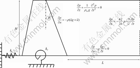
Fig. 1 Gravity dam and reservoir and foundation system
If the foundation of dam is assumed flexible, boundary conditions are given as
 (6)
(6)
 (7)
(7)
2) Governing equation of fluid
Hydrodynamic pressure in two-dimensional reference system is obtained from acoustic wave equation using the equation of continuity, Euler��s equation and state equation:
 (8)
(8)
where c is the velocity of the acoustic wave in water. Water is assumed a homogeneous, inviscid and linearly compressible and the flow is taken irrotational.
The hydrodynamic pressure distribution can be obtained by solving Eq. (9), subjected to the following boundary conditions:
At fluid-solid interface:
 (9)
(9)
At far end:
 (10)
(10)
To determine the hydrodynamic pressure on the dam due to horizontal ground motion under the assumption of infinite reservoir, the reservoir must be truncated at a reasonable distance. Sommerfeld��s boundary condition at the far-end truncated boundary is used and it can be written as
 (11)
(11)
At the bottom of fluid domain:
 (12)
(12)
where q is damping coefficient which is the fundamental parameter that characterizes the effects of the reservoir bottom materials and is given by Fenves and Chopra [8] as
 (13)
(13)
where �� is the ratio of the amplitude of the reflected hydrodynamic pressure wave to the amplitude of a vertically propagating pressure wave incident on the reservoir bottom.
At the bottom of reservoir, if the damping coefficient could be neglected, the boundary condition is
 (14)
(14)
At the free surface:
Considering the effects of surface waves of the fluid, the boundary condition of the free surface is taken as
 (15)
(15)
Assuming that the reservoir is initially at rest, the initial conditions are
 ,
,  (16)
(16)
3 Discretization of equations
The discretization of the model by FDM is shown in Fig. 2. Nx and Nz represent the numbers of nodal point in vertical and horizontal directions, respectively.
3.1 Discretization of governing equation of dam
Cross section and moment of inertia of the structure vary along the dam axis as
 ;
;  (17)
(17)
where
 ;
;  (18)
(18)
And the subscript ��0�� and ��1�� denote values at z=0 and z=h, respectively. A second-order semi-implicit scheme is used to obtain the displacement of dam at the end of the time step increment n+1, while the displacement of dam at time step n is known.
If the Euler-Bernoulli beam theory is used for extracting the governing equation of dam, equations for inner nodes can be written as


 (19)
(19)
where k denotes a particular spatial location and the superscript n denotes a particular time step and


 (20)
(20)
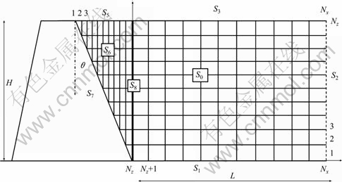
Fig. 2 Illustration of gird points and fluid-structure model
where k runs from 2 to Nz-1 and
 (21)
(21)
For the second node:

 (22a)
(22a)
where

 (22b)
(22b)
For Nz-th and (Nz-1)-th nodes:

 (23a)
(23a)
where


 (23b)
(23b)
 (24a)
(24a)
where

 (24a)
(24a)
If the foundation of dam is assumed flexible from boundary condition (3a), we have
(uk+1-2uk+uk-1)=R(uk+1-uk-1) u0=G1u1+G2u2 (25a)
where
 (25b)
(25b)
From boundary condition (3b), we have
 (26a)
(26a)
where
 (26b)
(26b)
From above equations, we have
 (27a)
(27a)
where
 (28a)
(28a)
For first node, we have

 (29a)
(29a)
where


 (29b)
(29b)
And for second node, we have

 (30a)
(30a)
where


 (30b)
(30b)
If the Timoshenko beam theory is used for extracting the governing equation of dam, for inner nodes, it can be written as

 (31a)
(31a)
where


 (31b)
(31b)
and
 (32a)
(32a)
 (32b)
(32b)
For the other equations:

 (33a)
(33a)
where

 (33b)
(33b)
k runs from 2 to Nz-1:
 (34a)
(34a)
 (34b)
(34b)
If the foundation of dam is assumed rigid from the boundary condition (5), we have
 (35a)
(35a)
where

 (35b)
(35b)
And
 (36a)
(36a)
where

 (36b)
(36b)
If the foundation of dam is assumed flexible from the boundary condition (6), we have
 (37a)
(37a)
 (37b)
(37b)
Substituting the above equation into Eqs. (32) and (34) yields
 (38a)
(38a)
where


 (38b)
(38b)
 (39a)
(39a)

 (39b)
(39b)
3.2 Discretization of governing equation of reservoir
A second-order explicit scheme is used to obtain the hydrodynamic pressure at the end of the time increment n+1, while the hydrodynamic pressure is known at time step n. If points k and i are chosen as the base points, the governing equations at time step n+1 can be written as

 (40a)
(40a)
where

 (40b)
(40b)
And i and k run from Nz+1 to Nx-1 and 1 to Nz-1 respectively.
At bottom of fluid domain (S1):

 (41)
(41)
with i running from Nz+1 to Nx-1 and 
At the Truncation Surface (S2):
 (42a)
(42a)
 (42b)
(42b)
and k running from 2 to Nz-1.
At the free surface, considering the effects of surface waves of the fluid, the free surface is divided into three sections, namely S3, S4 and S5.
For S3 boundary:

 (43a)
(43a)
 (43b)
(43b)
for i=Nz,��Nx-1.
For S4 boundary (k=Nz, i=Nz):

 (44a)
(44a)

 (44b)
(44b)
where

 and
and  .
.
For S5 boundary:

(45a)
 (45b)
(45b)

 (45c)
(45c)
for i=2,��Nz-1.
For S6 boundary:

 (46)
(46)
for i=2,��, Nz-1 and k=3, ��, Nz-1.
At fluid/solid interface (S7):

 (47)
(47)
For S8 boundary:

 (48a)
(48a)

 (48b)
(48b)
with k=2, ��,Nz-1.
For special point with k=1 and i=Nx:

 (49a)
(49a)
 (49b)
(49b)
For special point with k=Nz and i=Nx:

 (50a)
(50a)

 (50b)
(50b)
For special node with k=1 and i=Nz:

 (51a)
(51a)
 (51b)
(51b)
4 Numerical results
A computer code based on the algorithm described above is developed to determine the hydrodynamic pressure distribution on a two-dimensional structure exposed to infinite fluid media and the displacement of dam. As for examining the accuracy of the proposed algorithm, two benchmark problems are solved and the results are compared with the available solutions. In the first example, flexible dam with vertical upstream is analysed and the results are compared with semi-analytical solution. In the second example, rigid dam with inclined upstream face is analysed and the results are compared with FEM and dual-reciprocity boundary element methods (DBREM) and semi-analytical solution. Then, the effects of the free surface waves and the reservoir bottom absorption and flexible foundation of dam are included for the analysis of the third example and the Timoshenko beam theory is used in this example. In all analyses, the fluid is characterized by a mass density ��w=1 000 kg/m3 and a wave velocity c=1 439 m/s, and the reservoir is assumed horizontal. Ramp acceleration (Fig. 3.) and El Centro earthquake 1940 (Fig. 4.), applied along the upstream�Cdownstream direction, are used.
In all conditions, the dimensionless hydrodynamic pressure is taken as P/��wgH, where g is the acceleration due to gravity.
4.1 Example I: Flexible dam with vertical upstream face (��=0)
In the first example, analysis of a variable section
dam of 180 m in height is presented. The dam has an elasticity modulus of E=3.5 GPa and mass density of ��=2.4��103 kg. Variations of cross section and moment of inertia are

 (52)
(52)
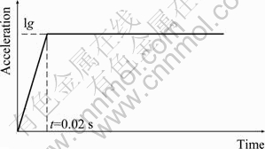
Fig. 3 Ramp type seismic acceleration
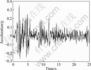
Fig. 4 North-south component of El Centro (1940) ground motion
In this example, for the governing equation of the dam, the Euler-Bernoulli beam theory is used. The displacement at the top of structure and the hydrodynamic pressure at the bottom of the dam without the effects of bottom materials and free surface waves are obtained and the results are compared with Attarnejad and Farsad��s semi-analytical solution [4], as depicted in Figs. 5-8.
The appropriate values of ��t, ��x, ��z and L are detected as 0.001 s, 9 m, 10 m and 5H, respectively, and for far end of the reservoir, Sommerfeld��s boundary condition is implemented. It is observed that the calculated values of the hydrodynamic pressures at the bottom of dam and the displacement of dam crest reasonably agree with those obtained by the semi-analytical solution.
4.2 Example II: Rigid dam with inclined upstream face
The purpose of the following example is to investigate the accuracy of algorithm for the inclined dam dynamic analysis. In the present analysis, the dam is assumed to be rigid and the system is subjected to ramp acceleration in the horizontal direction. The effects of reservoir bottom absorption and the free surface waves are ignored in the analysis. The same material properties of the dam and the reservoir of the previous example are used. The appropriate values of ��t, ��x, ��z and L are detected as 0.001 s, 9 m, 10 m and 5H, respectively. When the hydrodynamic pressure reaches the peak value at the bottom, the distribution of hydrodynamic pressure in the face of rigid dam with respect to depth and the hydrodynamic pressure at bottom of dam versus time for ��=30�� are obtained and the results are compared with FEM, dual-reciprocity boundary element methods (DBREM) [25] and semi-analytical solution [10] (Figs. 9 and 10). From both figures, it can be seen that the results obtained are in good agreement with semi-analytical solution and FEM and DBREM. Therefore, the applied FDM is efficient and correct for the analysis of the inclined dam.
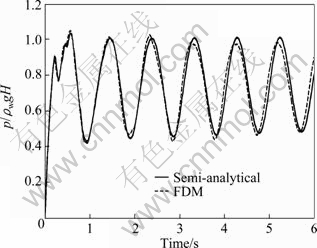
Fig. 5 Hydrodynamic pressure at toe subjected to ramp acceleration
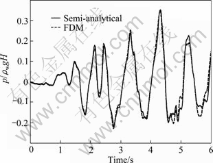
Fig. 6 Hydrodynamic pressure at toe of dam subjected to El Centro ground motion
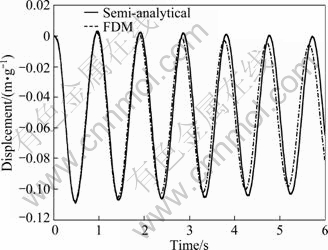
Fig. 7 Displacement of top of dam subjected to ramp acceleration
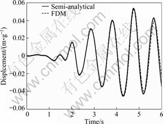
Fig. 8 Displacement of top of dam subjected to El Centro ground
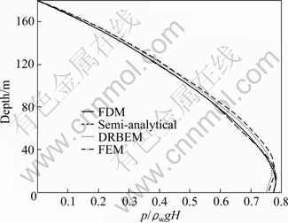
Fig. 9 Comparison of hydrodynamic pressure on face of inclined dam (��=30��)
4.3 Example III: Flexible dam with inclined upstream face
In the third example, the analysis of a variable section dam of 120 m in height is presented. The dam has an elasticity modulus of E=350 GPa, mass density of ��=2.4��103 kg/m3, Poisson ratio of v=1/3, shear shape factor of k=5/6 and the share modulus (G) is obtained from following equation:
 (53)
(53)
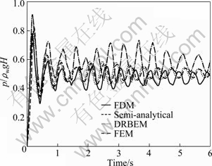
Fig. 10 Comparison of hydrodynamic pressure at toe of dam for inclined dam (��=30��)
Variations of cross section and moment of inertia are

 (54)
(54)
Variable �� changes from 0�� to 30�� while the values of the areas in down and up of dam are constant. In this analysis, the dam is assumed flexible. The Timoshenko beam theory is used for extracting the governing equation of dam. The appropriate values of ��t, ��x, ��z and L are 0.000 5 s, 3 m, 4 m and 5H, respectively. In the following figures, ��FSW=0�� indicates that the effect of free surface waves is ignored and ��FSW=1�� indicates that the effect of free surface waves is included. For wave reflection ratio (��), since values from 0 to 1 covering the wide range of material are encountered at the bottom of reservoirs, results are obtained for three different values, i.e. ��=1, ��=5 and ��=0.
At first, the foundation of dam is assumed rigid. And the wave reflection and FSW are considered as 0.5 and 1, respectively. The displacement of dam crest and the hydrodynamic pressure in the toe of dam are calculated and compared with those achieved based on the Euler-Bernoulli beam theory (Figs. 11-13). It is shown when the shear deformation and the rotational inertia of dam are taken into account, the displacement of dam crest and the hydrodynamic pressure in the toe of dam increase.
The hydrodynamic pressure in the toe versus time and the displacement of dam crest for the dam that are subject to ramp acceleration for different values of �� and FSW, as depicted in Figs. 14 and 15, respectively. It is clearly observed that considering the effect of surface waves, the hydrodynamic pressure in the toe and displacement of dam crest increase. Considering the effects of free surface waves, the maximum values of the hydrodynamic pressure and the displacement of dam crest increase. The effect of reservoir bottom absorption on results in this analysis is inconsiderable.
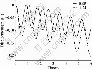
Fig. 11 Displacement of top of dam subjected to ramp acceleration for different beam theory
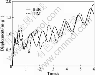
Fig. 12 Hydrodynamic pressure at toe of dam subjected to ramp acceleration for different beam theory
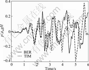
Fig. 13 Hydrodynamic pressure at toe of dam subjected to El Centro ground motion for different beam theory
The hydrodynamic pressure in the toe versus time and the displacement of dam crest for the dam subjected to El Centro earthquake are depicted in Figs. 16 and 17, respectively. The effect of free surface waves on results in this analysis is inconsiderable. As �� decreases, i.e. wave absorption at the reservoir bottom increases, the hydrodynamic pressure at the toe decreases.
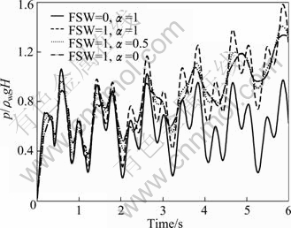
Fig. 14 Hydrodynamic pressure at toe subjected to ramp acceleration for simultaneous effects of reservoir bottom absorption and free surface waves (��=15��)
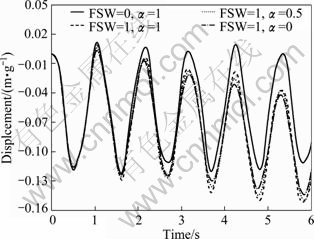
Fig. 15 Displacement of dam crest subjected to ramp acceleration for simultaneous effects of reservoir bottom absorption and free surface waves (��=15��)
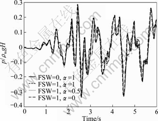
Fig. 16 Hydrodynamic pressure at toe subjected to El Centro ground motion for simultaneous effects of reservoir bottom absorption and free surface waves (��=15��)
In the next analysis, the effects of free surface waves and the reservoir bottom absorption are ignored. When the hydrodynamic pressure reaches the peak value at the bottom for different inclinations of the upstream face under the ramp acceleration and El Centro earthquake, the hydrodynamic pressure distribution along the reservoir/structure interface with respect to depth is plotted in Figs. 18 and 19, respectively. It can be seen that, for any fixed height z, the hydrodynamic pressure on upstream face of flexible dam decreases as the inclination angle �� increases. Also for �ȡ�0��, the maximum amount of the hydrodynamic pressure on the flexible dam face is not produced in the toe. As �� decreases, the maximum amount of hydrodynamic pressure is produced in distance away from the toe. As shown in Figs. 18 and 19, when the dam is assumed rigid, the hydrodynamic pressure on the dam is less than the hydrodynamic pressure on the flexible dam.
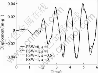
Fig. 17 Displacement of crest subjected to El Centro ground motion for simultaneous effects of reservoir bottom absorption and free surface waves (��=15��)
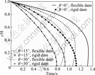
Fig. 18 Hydrodynamic pressure distribution on upstream face of dam for different sloping dams under ramp acceleration
The displacement of dam crest for different inclinations of the upstream face under the ramp acceleration and El Centro earthquake is plotted in Figs. 20 and 21, respectively. It is shown that, by increasing ��, the displacement of dam crest decreases. Such a decreasing is due to decrease of the hydrodynamic pressure on the upstream face dam. In next step, the dam foundation is assumed flexible and it is modeled by two separate elastic springs i.e. the translational and rotational springs, as shown in Fig. 1. The displacement of dam crest and the hydrodynamic pressure in the toe of dam for different values of springs are calculated and depicted in Figs. 22 and 23.
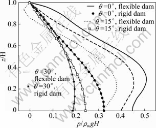
Fig. 19 Hydrodynamic pressure distribution on upstream face of dam for different sloping dams under El Centro earthquake
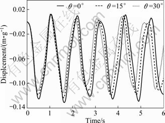
Fig. 20 Displacement of dam crest for different sloping dams under ramp acceleration
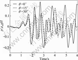
Fig. 21 Hydrodynamic pressure at toe for different sloping dams under El Centro earthquake
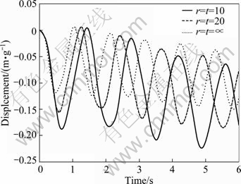
Fig. 22 Displacement of dam crest for different spring stiffness coefficients under ramp acceleration
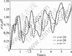
Fig. 23 Hydrodynamic pressure at toe for different spring stiffness coefficients under El Centro earthquake
With considering the effect of dam foundation, the displacement of dam crest and the hydrodynamic pressure in the toe of dam increase.
5 Conclusions
1) The effect of surface waves on the hydrodynamic pressure for the dam-reservoir under ramp acceleration is considerable, while it is negligible for the El Centro earthquake.
2) Considering that the flexibility of the dam results in significant effects on hydrodynamic pressure, the value of hydrodynamic pressure on dam increases.
3) While slope of upstream face of dam due to the decrease of the hydrodynamic pressure on the upstream face dam increases, the displacement of dam crest decreases.
4) When the Timoshenko beam theory is taken into account, the displacement of dam crest and the hydrodynamic pressure in the toe of dam increase with respect to situation in which that the Euler-Bernoulli beam theory is used.
5) When the foundation of dam is assumed flexible, the response of system increases.
References
[1] WESTERGAARD H M. Water pressure on dams during earthquakes [J]. Trans ASCE 1933, 98: 418-433.
[2] CHOPRA A T. Hydrodynamic pressures on dams during earthquakes [J]. J Engng Mech Div ASCE, 1967, 93(6): 205-223.
[3] LEE G C, TSAI C S. Time-domain analyses of dam-reservoir system. I: exact solution [J]. J Eng Mech, 1990, 117(9): 1990-2006.
[4] ATTARNEJAD R, FARSAD A R. Closed-form analysis of dam-reservoir interaction in time-domain including variable dam thickness [J]. J Faculty of Engng University of Tehran, 2005, 39: 329-340.
[5] SAINI S, BETTESS P, ZIENKIEWICZ O C. Coupled hydrodynamic response of concrete dams using finite and infinite elements [J]. Earthquake Engng Struct Dyn, 1978, 6: 363-374.
[6] CHOPRA A K, CHAKRABARTI P. Earthquake analysis of concrete gravity dams including dam-fluid-foundation rock interaction [J]. Earthquake Engng Struct Dyn, 1981, 9: 363-383.
[7] HALL J F, CHOPRA A K. Two dimensional dynamic analysis of concrete gravity and embankment dams including hydrodynamic effects [J]. Earthquake Engng Struct Dyn, 1982, 10: 305-332.
[8] FENVES G, CHOPRA A K. Earthquake analysis of concrete gravity dams including bottom absorption dam�Cwater�Cfoundation rock interaction [J]. Earthquake Engng Struct Dyn, 1984, 12: 663-683.
[9] LOTFI V, ROESSET J M, TASSOULAS J L. A technique for the analysis of the response of dams to earthquakes [J]. Earthquake Engng Struct Dyn, 1987, 15: 463-490.
[10] TSAI C S, LEE G C, KETTER R L. A semi-analytical method for time domain analyses for dam�Creservoir interactions [J]. Int J Num Meth Engng, 1990, 29: 913-933.
[11] MAITY D, BHATTACHARYYA S K. Time domain analysis of infinite reservoir by finite element method using a novel far-boundary condition [J]. Finite Elem Anal Des, 1999, 32: 85-96.
[12] GOGOI I, MAITY D. A non-reflecting boundary condition for the finite element modeling of infinite reservoir with layered sediment [J]. Adv Water Resour, 2006, 29: 1515-1527.
[13] BOUAANANI N, LU F Y. Assessment of potential-based fluid finite elements for seismic analysis of dam�Creservoir systems [J]. Comput Struct, 2009, 87: 206-224.
[14] HUMAR J L, JABLONSKI A M. Boundary element reservoir model for seismic analysis of gravity dams [J]. Earthquake Engng Struct Dyn, 1988, 16: 1129-1156.
[15] MEDINA F, DOMINGUEZ J. Boundary elements for the analysis of the seismic response of dams including dam�Cwater�Cfoundation interaction effects [J]. Eng Anal Bound Elem, 1989, 6: 152-157.
[16] BELYTSCHKO T, LU Y Y. A variational coupled FE-BE method for transient problem [J]. Int J Num Meth Engng, 1994, 37: 91-105.
[17] CZYGAN O, VAN ESTORFF O. Fluid-structure interaction by coupling BEM and nonlinear FEM [J]. Eng Anal Bund Elem, 2002, 26: 773-779.
[18] von ESTORFF O, ANTES H. An FEM-BEM coupling for fluid-structure interaction in the time domain [J]. Int J Num Meth Engng, 1991, 31: 1151-1168.
[19] NATH B. Coupled hydrodynamic response of a gravity dam [J]. Proc Inst Civ Engng, 1971, 48: 245-257.
[20] HUNG T K, WANG M H. Nonlinear hydrodynamic pressure on rigid dam motion [J]. J Eng Mech ASCE, 1987, 113: 482-499.
[21] HUNG, T K, CHEN B F. Nonlinear hydrodynamic pressure on dams [J]. J Engng Mech, 1990, 116 (6): 1372-1391.
[22] WANG M H, HUNG T K. Three-dimensional analysis of pressures on dams [J]. J Engng Mech, 1990, 116(6): 1290-1304.
[23] CHEN B F, HUNG T K. Dynamic pressure of water and sediment on rigid dam [J]. J Engng Mech, 1993, 119(7): 1411-1433.
[24] CHEN B F. Nonlinear hydrodynamics effects on concrete dam [J]. Eng Struct, 1996, 18: 201-212.
[25] TASKIN B, KUCUKARSLAN S. Ts.: A computationally efficient solution of the wave equation for the transient response of infinite [J]. Arch Appl Mech, 2005, 75: 68-77.
(Edited by YANG Bing)
Received date: 2011-12-14; Accepted date: 2012-01-17
Corresponding author: R. Attarnejad; Tel: +98-21-61112225; E-mail: Attarnjd@ut.ac.ir

