Trans. Nonferrous Met. Soc. China 22(2012) s275-s279
Characterization of plastic behaviour of sheet metals by hydraulic bulge test
Lucian  , Dan-Sorin
  , Ioan NICODIM, Ioan CIOBANU, Dorel BANABIC
CERTETA Research Centre, Technical University of Cluj-Napoca, Cluj-Napoca, Romania
Received 28 August 2012; accepted 25 October 2012
Abstract: In the hydraulic bulge tests, dies with both circular and elliptical apertures were used. A recently proposed methodology was used to determine the equivalent stress―strain curves by bulging through elliptical dies. This methodology combines an analytical approach with the experimental data measured by an ARAMIS system. In the hydraulic bulge test using elliptical dies, as the die ellipticity ratio decreases, the equivalent stress―strain curves tend to move away from the curve obtained from bulging through circular die. The forming limit diagram in the range of positive minor strain of a DC04 sheet steel is also determined by using bulge test.
Key words: hydraulic bulge test; stress―strain curves; forming limit diagram
1 Introduction
The most important advantage of the hydraulic bulge test is the absence of the contact (the frictional interactions) between tools and specimens in the area of interest, which simplifies the analytical solutions for the calculation of stress and strain, but also ensures the repeatability of the test.
The hydraulic bulge test is mostly used for the determination of stress―strain curves in biaxial stress state. The hydraulic bulge test is the subject of many scientific papers. HILL [1] developed analytical models for the calculation of polar thickness and curvature radius. He neglected the influence of the fillet radii of the die. The accuracy of the formulas proposed by HILL [1] has been improved by CHAKRABARTY and ALEXANDER [2] by studying the effect of hardening. Furthermore, SHANG and SHIM [3] extended the formulas proposed by HILL in order to take into account the fillet radius of the die insert. ATKINSON [4] also improved the accuracy of the analytical predictions referring to the polar thickness and dome radius. KRUGLOV et al [5] developed a formula for the calculation of the polar strains. BANABIC et al [6,7] developed analytical models for the computation of the pressure-time relationship for the bulging of superplastic materials through elliptical dies. et al [8-11] developed the analytical models for the determination of stress―strain curves using dies with circular and elliptical apertures. Experimental studies were performed for the assessment of the accuracy of some analytical models for the calculation of polar thickness and dome radius [12].
The hydraulic bulge test is also an important tool in the determination of the forming limit curves (FLC). By varying the aperture ratio of the dies with elliptical aperture, different strain paths can be obtained, making thus possible to determine points on the FLC in the positive range of the minor strain.
The aim of the work is to characterize the plastic behavior and formability of sheet metal using the results obtained from the hydraulic bulge test. The equivalent stress―strain curves, the forming limit diagram (FLD) in the range of positive minor strain are used to characterize the plastic behaviour and formability of a DC04 sheet steel.
2 Analytical model
2.1 Principle of hydraulic bulge test
In the hydraulic bulge test, the flat specimen is firmly clamped on its contour between a blank holder and a die, as seen in Fig. 1.
When the fluid, under uniform increasing pressure, gets into the hydraulic chamber, the blank is deformed through the die heaving a circular or an elliptical aperture (Fig. 1). The blank holder force (Q) should be high enough to avoid the radial slipping of the specimen during the test. The fracture occurs in the polar region of the specimen when the material strain exceeds its forming limit.
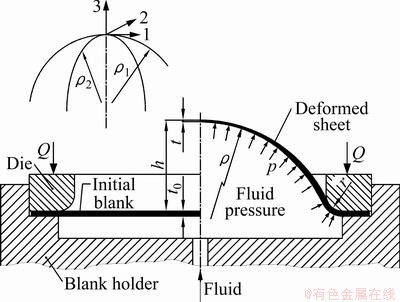
Fig. 1 Scheme of hydraulic bulge test
2.2 Circular bulging
The relationship used for the calculation of the polar stress is based on Laplace’s equation from the membrane theory. For an axially symmetric element, under the action of uniform pressure the equilibrium equation can be written as
 (1)
(1)
where σ1 and σ2 are the principal surface stresses; ρ1 and ρ2 are the curvature radii of the bulge in the two meridian sections (Fig. 1); p is the hydraulic pressure; t is the actual polar thickness of the specimen.
On the basis of the assumption that the material is isotropic and the shape of the deformed specimen is spherical, the bulge radius is the same in any meridian section ρ1 ρ2=ρ and the polar stresses are also balanced σ1σ2=σ[13].
For a spherical membrane with a very small ratio between the radius of curvature and polar thickness, it has been concluded that the meridian stress is much higher than the bending stress, and therefore the effect of bending can be neglected [14].
In the membrane theory, the normal component of the stress is also neglected. Therefore, the equivalent stress, also called biaxial stress (σb), can be calculated using the following equation:
 (2)
(2)
By assuming that the material is incompressible, and the shape of deformed specimen is spherical, the biaxial strain (εb) is equal to the true thickness strain in the polar region. Therefore, the equation used for the calculation of biaxial strain is
 (3)
(3)
where t0 is the original sheet thickness. Based on the material incompressible, the strain ε3 in the thickness direction is -(ε1+ε2) and the actual thickness becomes
 (4)
(4)
where ε1 and ε2 are the principal surface strains.
Assuming that the material is isotropic and the shape of the deformed specimen is spherical, the surface strains are equal to each other (ε1=ε2), and therefore the Eq. (4) transforms to
 (5)
(5)
The biaxial stress in Eq. (2) can be calculated on the basis of three variables: the internal pressure recorded during the experiment using a pressure gauge; the bulge radius and the average thickness determined using the ARAMIS system.
2.3 Elliptical bulging
The main feature of the hydraulic bulge test through elliptical dies is the elliptical shape of the die aperture (see Fig. 2). By varying the ratio between the minor and major axes a and b, respectively, of the elliptical aperture, different strain paths may be obtained during the bulge test.
The analytical approach used for the determination of stress―strain curve is shortly described below but more details can be found in Ref. [10]. The deformed surface of the specimen is approximated by a rotational ellipsoid (the rotational axis is x1 in Fig. 2).
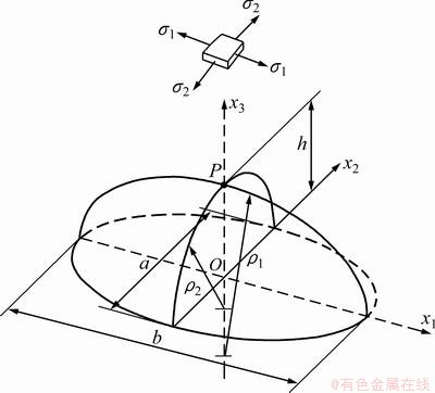
Fig. 2 Geometry of specimen subjected to bulging through die with elliptical aperture
The polar values of the principal stress can be evaluated using Timoshenko’s formulas [15]:
 (6)
(6)
The equivalent stress can be defined as follows:
 (7)
(7)
where
 (8)
(8)
is considered a constant ratio for a given geometry of the die hole.
The equivalent strain can be defined as follows:
 (9)
(9)
The current value of the polar thickness can thus be obtained from the following relationship:
 (10)
(10)
One may notice that Eq. (7) reduces to Eq. (2)  , Eq. (9) reduces to Eq. (3)
  and Eq. (10) reduces to Eq. (5) for b =1, thus consistent with the formulas used in the case of the hydraulic bulging through circular dies.
The hardening curve relating the equivalent stress and the equivalent strain can be constructed using Eqs. (7) and (9). These relationships are valid for the hydraulic bulging with dies having both elliptical and circular holes. Equations (7) and (9) need the experimental determination of the following process parameters: current value of the pressure acting on the bottom face of the specimen p, the two radii ρ1 and ρ2 and the meridian strain ε2.
3 Material
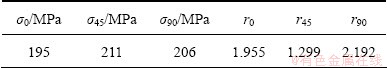
DC04 low carbon steel with a nominal thickness of 0.85 mm, mostly used for automotive components and body panels was chosen for the experiments in this work. The mechanical parameters of the tested sheet were determined by uniaxial tensile tests performed on a Zwick Roell Z150 testing machine. The stress―strain curves, the yield stress and the anisotropy coefficients were determined for specimen cut from the sheet at 0°, 45° and 90° angles measured from the rolling direction (RD). Table 1 lists the mechanical parameters of the DC04 steel obtained from the uniaxial tensile tests.
Table 1 Mechanical parameters of DC04 steel sheet
4 Experiments
Figure 3 shows a general view on the equipment used to perform the hydraulic bulge tests. This consists of a hydraulic device for the pressure development, a bulging device containing the die and a 3D optical measurement system ARAMIS. The design of the bulging device allows the testing of sheet metals by hydraulic bulging, as well as by punch stretching. The current values of the pressure and polar height were continuously recorded using an ARAMIS system.
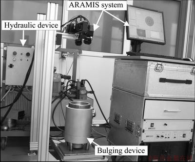
Fig. 3 Experimental setup
Four ellipticity ratios (a/b) were used: 0.4 (32/80), 0.6 (48/80), 0.8 (64/80), and 1 (circular hole with 80 mm diameter). The fillet radius of the die was r=4 mm in all cases. The specimens were cut from the tested sheet having the diameter of 158 mm.
5 Results
5.1 Pressure versus bulge height curves
Figure 4 shows the effect of the die aspect ratio on the hydraulic pressure versus bulge height curves. It can be seen that when the die aspect ratio decreases from 1 to 0.4, the maximum internal hydraulic pressure increases from 12.73 MPa to 20.7 MPa and the bulge height decreases from 31.8 mm to 11.8 mm, respectively.
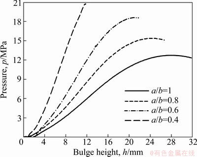
Fig. 4 Relationship between pressure and bulge height
5.2 Equivalent stress―equivalent strain curves
Figure 5 shows the equivalent stress―strain curves obtained from the hydraulic bulge tests using dies with different aspect ratios.
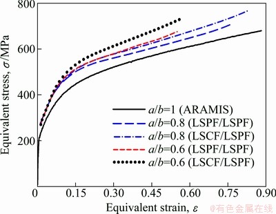
Fig. 5 Equivalent stress―strain curves
5.2.1 Bulging using circular dies
In the case of the hydraulic bulging through circular dies (a/b=1), the biaxial stress was calculated on the basis of Eq. (2) and the biaxial strain on the basis of the Eq. (3), using the ARAMIS software. The biaxial stress―strain curves obtained from the bulge test using a circular die are shown in Fig. 5 with continuously line.
5.2.2 Bulging using elliptical dies
In order to determine the equivalent stress―equivalent strain curves from the bulging through elliptical dies, Eqs. (7)-(10) were used.
The bulge geometries obtained using the ARAMIS software, at different stages of bulging, were cut with the Ox2x3 and Ox1x3 planes and the profile along the minor (a) and major (b) axis were obtained (Fig. 2). The data describing these profiles were used to determine the radii of curvature (ρ1 and ρ2) of the specimen, by the least square approximation. The data from the Ox1x3 profile were fitted using only the least square parabola fitting (LSPF) method. The data from the Ox2x3 profile were fitted using the LSPF method as well as the least square circle fitting (LSCF) method.
Two cases were used for the calculation of β-coefficient (Eq. (8)).
Case 1 (LSPF/ LSPF): ρ2 was determined by LSPF and ρ1 by LSPF.
Case 2 (LSCF/ LSPF): ρ2 was determined by LSCF and ρ1 by LSPF.
The circumferential strain (ε2) measured by the ARAMIS system along the minor axis of the die hole was also replaced in Eqs. (9) and (10) for obtaining the equivalent strain and the current polar thickness, respectively.
The equivalent stress―strain curves obtained from the bulging through elliptical dies are shown in Fig. 5.
From Fig. 5 we can notice that as the die ellipticity ratio decreases, the equivalent stress―strain curves tend to move away from the curve obtained from bulging through circular die (a/b=1). From Fig. 5, it is also found that curves obtained in the case 1 (LSPF/ LSPF) are always lower than the curves obtained in the case 2 (LSCF/ LSPF), for a/b=0.8 as well as for a/b=0.6. This can be explained by the fact that the radius of curvature (ρ2) along the minor axis is higher when it is obtained by LSCF compared with ρ2 obtained by LSPF. The biaxial stress―biaxial strain curves, obtained using a circular die, were used in order to determine the biaxial yield stress (Yb). This the principle of the equivalent plastic work was used [16]. The biaxial yield stress was found to be Yb= 249.72 MPa. The strain ratio (εTD/εRD) obtained from the bulge tests through circular dies was also used for the determination of the biaxial anisotropy coefficient (rb). The biaxial anisotropy coefficient was determined as an average value of the εTD/εRD ratios obtained from a domain in which this ratio is as uniform as possible [16]. The value of rb was found to be 0.957.
5.3 Forming limit diagram
Figure 6 shows the forming limit diagram for the positive minor strains of the DC04 sheet steel. On this diagram the points from 1 to 4 were obtained from the hydraulic bulge tests and the points 5 and 6 from punch stretching testing. From Fig. 6, it is found that the strain ratio (εTD/εRD) increases when the ellipticity ratio (a/b) decreases from 1 to 0.4.
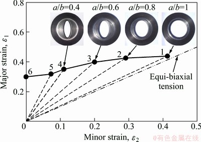
Fig. 6 FLD for DC04 sheet steel
6 Conclusions
1) The hydraulic bulge test was used to characterize the plastic behaviour and the formability of a DC04 sheet steel. The equivalent stress―strain curves and the forming limit diagram in the range of positive minor strain and the yield locus were used to characterize the plastic behaviour and formability of the tested material.
2) In the hydraulic bulge test using elliptical dies, as the die ellipticity ratio decreases, the equivalent stress―strain curves tend to move away from the curve obtained from bulging through circular die. The strain ratio (major strain/minor strain) increases when the ellipticity ratio (a/b) decreases from 1 to 0.4.
Acknowledgments
This paper was supported by the projects of POSDRU/89/1.5/S/52603, POSDRU/107/1.5/S/78534 and PCCE 100/2010.
References
[1] HILL R. A theory of the plastic bulging of a metal diaphragm by lateral pressure [J]. Philosophical Magazine, 1950, 41(7): 1133-1142.
[2] CHAKRABARTY J, ALEXANDER J M. Hydrostatic bulging of circular diaphragms [J]. The Journal of Strain Analysis for Engineering Design, 1970, 5(3): 155-161.
[3] SHANG H M, SHIM V P W. A model study of the effect of the size of the die shoulder in hydroforming [J]. Journal of Mechanical Working Technology, 1984, 10(3): 307-323.
[4] ATKINSON M. Accurate determination of biaxial stress―strain relationships from hydraulic bulging tests of sheet metals [J]. International Journal of Mechanical Sciences, 1997, 39(7): 761-769.
[5] KRUGLOV A A, ENIKEEV F U, LUTFULLIN R Y A. Superplastic forming of a spherical shell out a welded envelope [J]. Materials Science and Engineering A, 2002, 323(1-2): 416-426.
[6] BANABIC D,  D S. Closed-form solution for bulging through elliptical dies [J]. Journal of Materials Processing Technology, 2001, 115(1): 83-86.
[7] BANABIC D, VULCAN M. Bulge testing under constant and variable strain rates of superplastic aluminium alloys [J]. Annals of CIRP, 2005, 54(1): 205-209.
[8] L, D S, BANABIC D. Analytical and experimental evaluation of the stress―strain curves of sheet metals by hydraulic bulge tests [J]. Key Engineering Materials, 2011, 473: 352-359.
[9] L, D S, BANABIC D. Determination of stress-strain curves of sheet metals by hydraulic bulge test [C]//ESAFORM International Conference 2011. Belfast, 2011: 1429-1434.
[10] L, D S, BANABIC D. A procedure for the evaluation of flow stress of sheet metal by hydraulic bulge test using elliptical dies [J]. Key Engineering Materials, 2012, 504-506: 107-112.
[11] L, D S, NICODIM I, CIOBANU I, BANABIC D. Investigation of bulge radius variation and its effect on the flow stress in the hydraulic bulge test [J]. Steel Research International, 2012: 395-399.
[12] KOC M, BILLUR E, CORA  N. An experimental study on the comparative assessment of hydraulic bulge test analysis methods [J]. Materials & Design, 2011, 32(1): 272-281.
[13] KULAR G S, HILLER M J. Re-interpretation of some simple tension and bulge test data for anisotropic metals [J]. International Journal of Mechanical Sciences, 1972, 14(1): 631-634.
[14] RANTA-ESKOLA A J. Use of the hydraulic bulge test in biaxial tensile testing [J]. International Journal of Mechanical Sciences, 1979, 21(8): 457-465.
[15] TIMOSHENKO S P, KRIEGER S W. Theory of plates and shells [M]. New York: McGraw-Hill, 1959.
[16] L, D S, NICODIM I, CIOBANU I, BANABIC D. Determination of material parameters of sheet metals using the hydraulic bulge test [J]. Acta Metallurgica Slovaca, 2012.
液压胀形金属板材的塑性行为表征
Lucian , Dan-Sorin , Ioan NICODIM, Ioan CIOBANU, Dorel BANABIC
CERTETA Research Centre, Technical University of Cluj-Napoca, Cluj-Napoca, Romania
摘要:采用圆形和椭圆形的模具进行液压胀形试验。利用最近提出的椭圆形模具胀形方法来确定等效应力―应变曲线。该方法将ARAMIS系统测得的实验数据与分析相结合。在使用椭圆形模具的液压胀形实验中,随着模具椭圆度的减小,等效应力―应变曲线逐渐远离圆形模具胀形的曲线。通过胀形测试来确定DC04钢板在正次应变范围内的成形极限图。
关键词:液压胀形试验;应力―应变曲线;成形极限图
(Edited by LI Xiang-qun)
Corresponding author: Dorel BANABIC; E-mail: banabic@tcm.utcluj.ro
DOI: 10.1016/S1003-6326(12)61719-1

