J. Cent. South Univ. (2016) 23: 2876-2882
DOI: 10.1007/s11771-016-3351-2

Adaptive trajectory linearization control for hypersonic reentry vehicle
HU Yu(胡钰)1, 2, WANG Hua(王华)1, 3, REN Zhang(任章)4
1. College of Mechatronic Engineering, North University of China, Taiyuan 030051, China;
2. Beijing Institute of Astronautic System Engineering, Beijing 100076, China;
3. School of Astronautics, Beijing University of Aeronautics and Astronautics, Beijing 100191, China;
4. School of Automation Science and Electrical Engineering, Beijing University of Aeronautics and Astronautics, Beijing 100191, China
 Central South University Press and Springer-Verlag Berlin Heidelberg 2016
Abstract: This paper presents an improved design for the hypersonic reentry vehicle (HRV) by the trajectory linearization control (TLC) technology for the design of HRV. The physics-based model fails to take into account the external disturbance in the flight envelope in which the stability and control derivatives prove to be nonlinear and time-varying, which is likely in turn to increase the difficulty in keeping the stability of the attitude control system. Therefore, it is of great significance to modulate the unsteady and nonlinear characteristic features of the system parameters so as to overcome the disadvantages of the conventional TLC technology that can only be valid and efficient in the cases when there may exist any minor uncertainties. It is just for this kind of necessity that we have developed a fuzzy-neural disturbance observer (FNDO) based on the B-spline to estimate such uncertainties and disturbances concerned by establishing a new dynamic system. The simulation results gained by using the aforementioned technology and the observer show that it is just due to the innovation of the adaptive trajectory linearization control (ATLC) system. Significant improvement has been realized in the performance and the robustness of the system in addition to its fault tolerance.
Key words: hypersonic reentry vehicle (HRV); trajectory linearization control (TLC); fuzzy-neural disturbance observer (FNDO); B-spline
1 Introduction
For the time being, HRV system has been highly appreciated for its high speed, long range and flexible trajectory form [1]. In addition, it enjoys a high speed range from subsonic to hypersonic up to Mach number 25, and, therefore, it can deal with a great variety of effects which had not been encountered before the development of the single monolithic vehicle. One of the most crucial aspects involving is the drastic change of the atmospheric environment. Besides, the model of the vehicle is by nature nonlinear and uncertain. The most sensitive problem in this respect is the attitude of the vehicle, the control of which should be taken as vital to stabilize the typical long bodies and big wings of the aerospace vehicles in the speed regime. The above features may account for the necessity why to design the attitude control system to be robust and highly stable.
As is known, traditional control systems are designed in the linear form, which is similar to approximate system dynamics only in the small domain of interest around the equal linearization. Nevertheless, the said method can only make the system poor in robustness, which leads to the needs to adopt a few other nonlinear control methods to overcome the said weak-points. To achieve the purpose, sliding mode control (SMC) becomes one of the most popular and powerful methodologies in this way to guarantee the stability of the closed-loop system and gain the satisfactory performance though there may exist likely modeling errors and uncertainties [2-4]. The structure of the system is switched each time when the state crosses the discontinuous surface, called sliding surface. However, the switched input may cause the chattering problem, leading to a difficult situation of engineering application.
Another method involving is the nonlinear dynamic inversion (NDI) [5-7], which has been used to eliminate the nonlinearity disturbances in the model by relieving them by the position of the feedback offset. What is more, the nonlinear control method can also be adopted as TLC to be used for the time-varying situations based on the NDI and the theory of differential algebraic spectrum [8]. The system may achieve partially exponential stability along the nominal trajectory because of the nonlinear decoupling and tracking caused by the TLC [9]. Thus, it can be seen that the method developed can be successfully applied to the controlling system of missiles and/or other reusable launching vehicles [10-12]. Since NDI is based on the accurate knowledge of the nonlinear system dynamics, the model of the system can be regarded as well matched with the onboard system of the vehicle, with all the system nonlinearities clarified thoroughly. However, for HRV, it is difficult to obtain the precise mathematical model, which may reduce the robustness in its performance due to the increase of the uncertainty in the case that it works in the adversary environments. Therefore, traditional TLC can no longer be properly used.
Seeing the above mentioned situations, a wide range of researches have been done recently to reduce the aforementioned inadequacies. For this reason, an approach was proposed to join the NDI with the artificial neural networks to make up for the inadequacies of the model in Ref. [13], and an approach was proposed to combine the NDI with H∞ synthesis for the reentry flight clearance [14]. The above simulation results could help us to find noticeable benefits from the conventional NDI, though the NDI could be still influenced by the lumped uncertainty introduced by the conservation.
Therefore, we brought about an adaptive TLC trajectory linearization controller so as to make the predictive model more compact and accurate, which can be further improved in comparison with the traditional TLC and the adaptive FNDO algorithm based on the B-spline to optimize the model parameters. Furthermore, we also established a new dynamic system to estimate the various disturbances and uncertainties with the help of the given dynamic information. At the same time, the compensation control regularity has also been worked out to empower the effects of the system. Therefore, the simulation results demonstrate that the proposed method has been entitled with the sufficient needed values.
2 Problem setup
Since the HRV system is working in the adversary environment and difficult to formulate a precise mathematical model, its dynamical model seems to be a temporally continuous scalar nonlinear system with the disturbance and uncertainty:
 (1)
(1)
where  is the state;
  is the input;
  is the output.

 and
and
 are assumed to be smooth and bounded; The uncertainties △f(x), △g(x) and d1(t) are supposed to be unknown though they are bounded, representing dynamic uncertainty, structured uncertainty, and outside disturbance respectively.
Now, let’s define the entire system disturbance by the following formula:

When compared with the common nonlinear system, the d of HRV is much larger, that is to say, the controller designed should be much stronger in robustness than usual.
Hypothesis 1: There are matrices g0(x) which can satisfy the following matching conditions:
 (2)
(2)
This work presents an improved controller to stabilize the nominal trajectory with the TLC law and B-spline fuzzy-neutral observer to make up for the system disturbance.
In the system, it is possible to gain the adaptive trajectory linearization controller with a binary freedom controller consisting of: 1) TLC law: an NDI to work out the nominal control  for any given nominal output trajectory, and to stabilize the nominal trajectory by using the linear state feedback control law △u; 2) a compensation control law ur that can be used to work out the modeling uncertainty, disturbance with an FNDO based on the B-spline. The overall controller configuration can be described in Fig. 1.
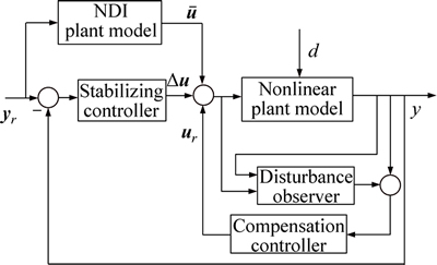
Fig. 1 Adaptive trajectory linearization control system configuration
3 Layout of trajectory linearization controller
As regard to the TLC theme [15], let d=0 and 

 be the nominal state. It would be possible for the equation to satisfy the output trajectory and the nominal control:
 (3)
(3)
The state error is supposed to be  whereas the tracking error control input is assumed to be
  then the nonlinear tracking error dynamic can be written as
 (4)
(4)
where

Hypothesis 2: e(t)=0 is an isolated equilibrium point of the nonlinear system, and  can be continuously differentiable, among which
  The Jacobian matrix
  is a bounded continuous function of t, which can meet the Lipschitz condition when D is satisfied.
By linearizing Eq. (4) along the nominal state and control  , the equation can be deduced as
 (5)
(5)
where


Hypothesis 3: The pair (A(t), B(t)) is supposed to be uniformly and totally controllable for all the allowable parameters in Eq. (5).
The tracking error state variables can be defined by equation 
The PI feedback control law can be given by equation  in which the gain matrices KI and KP can then be represented symbolically as the equations below:
 (6)
(6)
And, alternatively, the closed-loop tracking error dynamic can be rewritten as

 (7)
(7)
In the above gain matrices KI(t) and KP(t), the parameters can be gained from the close loop quadratic PD-eigenvalues:

with the constant damping  and the time-varying bandwidth ωni as follows:

The close loop tracking error dynamic can be rewritten as
 (8)
(8)
Thus, the exponential stability can be achieved in accordance with the TLC control law  followed by system Eq. (8). And, next, a result can be inferred as a result of the feedback exponential stabilization of the nonlinear system Eq. (4) according to the same control law, as shown in Ref. [16].
4 FNDO design
If  an FNDO and a compensation controller of the HRV can be used for creating a model to match with the unsteadiness and nonlinearity in the flight envelope wherein the stability and control derivatives are nonlinear and time-varying. It would be possible to rephrase the adaptive nonlinear tracking control law in the next equation:
 (9)
(9)
where ur should stand for the compensation control law.
4.1 Fuzzy neural network based on B-spline
The compensating electric current can be made approximated via a fuzzy neural network, as shown in Fig. 2.
The entire network is composed of four layers.
Layer I is the input layer where nodes at this layer are weighted, representing input linguistic variables.

where i=1, …, N; N and kui are used to denote the number of the input variable and the weight factor, respectively.
Nodes at Layer II are term nodes which are used to act as the membership functions to represent the terms of the respective linguistic variables. An appropriate choice of the basic functions is B-spline function on the basis of the smoothing techniques due to its excellent estimate ability with less complex equations [17], whereas a B-spline function serves as a piecewise polynomial [18].
Let equation x={x1, x2, …, xN+m} serve as the knot, where xi is the knot with  and the ith B-spline basis function of the order m, denoted by Bi,m, can be defined as follows [19]:
 (10)
(10)
 (11)
(11)
Herein, B-spline function can be rewritten as

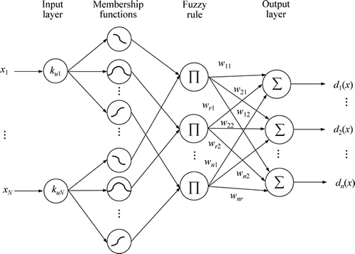
Fig. 2 Fuzzy neural network configuration
The three orders of the basis function are high enough to represent approximately the complex nonlinear functions, as shown in Fig. 3.
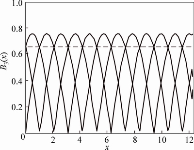
Fig. 3 Three lower orders of basis function
Each node at layer III represents a fuzzy rule written as

where j=1, …, r with r being the number of the nodes at layer III and  is the membership function value of the fuzzy variable xi with the jth fuzzy rule.
Layer IV is the output layer where the output of the network can be expressed as
 (12)
(12)
where m=1, …, n,  with n being the numbers of the outputs. And, in contrast,
  is an adjustable weighing factor.
Lemma 1: Let d(x)=[d1(x), d2(x), …, dn(x)]T be a nonlinear vector and ξ(x) denote the output of the layer II, and, then, the unknown d(x) can be simply described by the optimal weighting factor W=[w1, …, wn] plus a reconstruction error ε=[ε1, ε2, …, εm] by the universal approximation capability of the fuzzy logic system, as shown below:
 (13)
(13)
In the above equation, ε and W are supposed to be bounded by  and
and  for all εN>0.
Thus, symbol  is used to denote the vector 2-norm or matrix F-norm.
4.2 FNDO design
In this section, a new disturbance observer has been designed to estimate the total disturbance d.
To construct the fuzzy neural network system  which mimics the unknown disturbance d, the following FNDO system is designed:
 (14)
(14)
 (15)
(15)
 (16)
(16)
where μ is FNDO state vector; c>0 is FNDO parameter;  estimates the optimal weighting factor W.
Define ed=x-μ and  According to Eqs. (1) and (14), the dynamic of the disturbance observation error is expressed as
 (17)
(17)
 (18)
(18)
Theorem 1: Assume that the FNDO Eqs. (14)-(16) are used to estimate the disturbance. If the adjustable parameter vector of the FNDO is tuned by
 (19)
(19)
then the disturbance estimate error ed and the adjustable parameter error  are uniformly and ultimately bounded. Here, adaptive parameter ΓW is a positive-definite matrix and constant κ is positive.
Proof: Let the Lyapunov function candidate be given by
 (20)
(20)
where  denotes the trace of a matrix.
Differentiating Eq. (20) and substituting Eq. (19) into Eq. (20) yields:

 (21)
(21)
Define  If we have
  or
or  we would get
  , which means that disturbance estimate error ed and adjustable parameter error are uniformly and ultimately bounded within a residual ball
  and
and  respectively, based on Lyapunov stability theorem.
4.3 Compensation controller
Since the total disturbance d can be estimated by the FNDO, according to the matching conditions in Hypothesis 1, the compensation controller can be designed as
 (22)
(22)
Thus, the closed loop tracking error dynamic can be expressed as follows:
 (23)
(23)
Owing to Theorem 1, the adaptive trajectory linearization controller proposed in this work can make the nonlinear system achieve stability.
5 Algorithm test
In this section, we have done some numerical simulations to illustrate the effectiveness of the proposed controller by using a HRV model initiated by Winged-cone Configuration Langley Research Center in 1990 [20], in which the dynamic model adopted was referred to as Ref. [21]. It is also necessary to point out that the model here used was highly nonlinear and uncertain by nature, with additional disturbance. Therefore, we investigated their impact on the robust performance to be achieved.
When designing the attitude controller by ATLC, we applied the configuration shown in Fig. 4 both to the attitude error feedback loop and the angular rate error.
The close-loop PD-eigenvalues were assigned at  where
where for all channels in the inner and outer loop. For the nominal design, ωn=2.5 and 5.0 were true respectively for all the channels in the outer loop and inner loop. Whereas, for FNDO design, the set parameter c=0.5, the adaptive parameter ΓW=diag[5, 1, 5], and the constant κ=5.
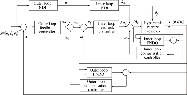
Fig. 4 Attitude tracking system configuration
The initial conditions for the vehicle were chosen as [α(0), β(0), σ(0)]=[10, 0, 0]. Simulations were formulated in MATLAB with the nominal control [αr, βr, σr]=[20, 0, 0].
To make the test more demanding, minor uncertainties were added, including the aerodynamic uncertainties and the unstructured environment disturbance, which could be taken as 20% and 0.5sint, respectively. Thus, it can be seen that both TLC and ATLC can produce stable tracking results, as shown in Fig. 5 (Case 1), though the basic TLC shows a larger tacking error.
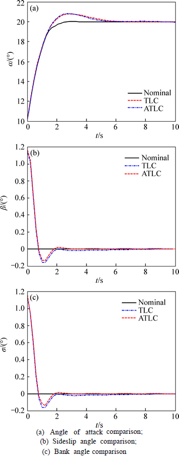
Fig. 5 Comparison curve Case 1:
Thus, increasing the aerodynamic maximum uncertainty in the parameters to 30% and the unstructured environment disturbances to 2+5sint, the comparison results can be shown in Fig. 6 (Case 2). The blue dots and dash lines are used to represent the TLC result while the red dashed one represents the ATLC result. The overcast result of TLC tends to be higher than that in the ATLC. Moreover, the angle of the attack in TLC result may still be oscillating around 20° in the range between 19.8° and 20.5° whereas the actual attitude would uniformly converge to the actual degrees determined by the actual status-in-situ, which tends to show that the basic TLC may completely lose the controllability and the ability to reject disturbance is weak. Compared with TLC, the ATLC can behave better in this case and promote the response faster. Moreover, it can behave more accurately than TLC in the case that the error becomes more serious, when the compensation observer can capture the uncertainty of the system.
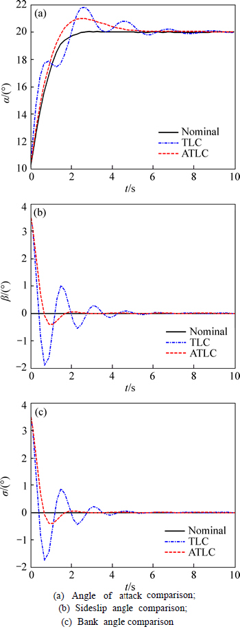
Fig. 6 Comparison curve Case 2:
From what is said above, it can be found clearly that ATLC can perform better in tracking error, raising time and overshoot so as to improve the regulation properties and enhance the robustness.
6 Conclusions
1) A novel ATLC scheme was proposed for HRV in the presence of modeling errors and uncertainties to identify and determine a tracking error regulation control law for stabilizing the nominal trajectory and a compensation control law for approximating the compound disturbance online.
2) The stability of the attitude tracking system has been proved by Lyapunov theory. The proposed control scheme can help to make more effective elimination of the tracking errors to achieve excellent approximation capability.
3) The simulation results demonstrate that both the TLC and the ATLC can produce stable tracking results under the condition when the uncertainties are minor. But with the increase of the uncertainty, the basic TLC would totally lose its controllability even when the ATLC remains to work well, which indicates that the performance, robustness and the fault tolerance of the redesigned controller have been significantly improved.
References
[1] TIAN X K, ZHU Q J. Flight dynamics modeling and analysis of flexible hypersonic flight vehicles [J]. Applied Mechanics and Materials, 2013, 275(3): 513-517.
[2] HALL C E, SHTESSEL Y B. Sliding mode disturbance observer- based control for a reusable launch vehicle [J]. Journal of Guidance, Control, and Dynamic, 2006, 29(6): 1315-1328.
[3] WANG Hong-xin, JIANG Ju, DU Jie, LEI A X. Sliding mode controller for hypersonic vehicle with parameters uncertainties [C]// 2014 IEEE Chinese Guidance, Navigation and Control Conference. Yantai: GNCC, 2014: 686-691.
[4] BENJOVENGO F P. Sliding mode control approaches for an autonomous unmanned robotic airship [C]// 18th AIAA Lighter- Than-Air System Technology Conference. Washington: AIAA, 2009: 1-11.
[5] SONNEVELDT L, CHU Q P, MULDER J A. Nonlinear flight control design using constrained adaptive back-stepping [J]. Journal of Guidance, Control, and Dynamics, 2007, 30(2): 332-336.
[6] QIN Chang-mao, QI Nai-ming, ZHU Kai. Active disturbance rejection attitude control design for hypersonic vehicle [J]. Journal of Systems Engineering and Electronics, 2011, 33(7): 1607-1610.
[7] SONG Jiang-shuang, REN Zhang, SHEN Zhen. Self-regulation control scheme for reusable launch vehicle reentry attitude control [C]// 2012 IEEE Fifth International Conference on Advanced Computational Intelligence. Nanjing: ICACI, 2012: 447-451.
[8] ZHU J J, BANKER B D, HALL C E. X-33 ascent flight controller design by trajectory linearization-a singular perturbational approach [C]// AIAA Guidance, Navigation, and Control Conference. Denver: AIAA, 2000: 1-5.
[9] ADAMI T A, ZHU J J. Flight control of hypersonic scramjet vehicles using a differential algebraic approach [C]// AIAA Guidance, Navigation, and Control Conference. Keystone: AIAA, 2006: 1-9.
[10] LI Hai-jun, HUANG Xian-lin, GE Dong-ming. Adaptive trajectory linearized control for maneuvering reentry vehicle [J]. Journal of Astronautics, 2011, 32(5): 1039-1046. (in Chinese)
[11] ZHU Bing, HUO Wei. Trajectory linearization control for a miniature unmanned helicopter [J]. International Journal of Control, Automation and Systems, 2013, 11(3): 286-295.
[12] PU Zhi-qiang, TAN Xiang-min, FAN Guo-liang, YI Jian-qiang. Robust trajectory linearization control of a flexible hypersonic vehicle in the presence of uncertainties [C]// 2013 IEEE International Conference on Mechatronics and Automation. Takamatsu: ICMA, 2013: 365-370.
[13] BURKEN J, NGUYEN N T, GRIFFIN B J. Adaptive flight control design with optimal control modification on an F-18 aircraft model [J]. National Aeronautics and Space Administration, 2010, 20(4): 1-17.
[14] RYSDYK R, CALISE A J. Robust nonlinear adaptive flight control for consistent handling qualities [J]. IEEE Transactions on Control System Technology, 2005, 13(6): 896-910.
[15] BEVACQUA T, BEST E, HUIZENGA A. Improved trajectory linearization flight controller for reusable launch vehicles [C]// 42nd AIAA Aerospace Science Meeting and Exhibit. Reno: AIAA, 2004: 1-13.
[16] KHALIL H K. Nonlinear systems[M]. New Jersey, USA: Prentice- Hall, 2002.
[17] CSURCSIA P Z, SCHOUKENS J, KOLLAR I. Identification of time-varing systems using a two-dimensional B-spline algorithm [C]// IEEE Instrumentation and Measurement Technology Conference. Graz: IMTC, 2012: 1056-1061.
[18] NAKAGAWA Y. A new method for discrete optimization problem [J]. Electronics and Communications in Japan, 1990, 73(11): 99-106.
[19] CONG Shuang, SONG Rui-xiang, QIAN Zhen. Improved B-spline fuzzy neural networks [J]. Control Theory and Applications, 2001, 18(2): 277-280. (in Chinese)
[20] OHN D, SHAUGHNESSY, PINCHNEY S Z. Hypersonic vehicle simulation model: Winged-cone configuration [R]. Washington D C: NASA Technical Memorandum, 1990.
[21] ZHAO Han-yuan. Flight vehicle reentry dynamics and guidance [M]. Changsha: National University of Defense Technology Press, 1997. (in Chinese)
(Edited by YANG Hua)
Received date: 2016-03-30; Accepted date: 2016-08-16
Corresponding author: HU Yu, PhD candidate; Tel: +86-13466783986; E-mail: hu-yu-1987@163.com

