�����ϲ۳��ж��������㼣
��Դ�ڿ����й���ɫ����ѧ��(Ӣ�İ�)2020���7��
�������ߣ������� л��׳ ��ΰ �Ժ���
����ҳ�룺1956 - 1963
�ؼ��ʣ�����⣻�ϲ۳ģ�������軯��㼣
Key words��aluminum reduction; spent pot lining; fluorides; cyanide; footprint
ժ Ҫ�������ϲ۳�(SPL)���京�д��������Է�����������綾�軯�������ΪΣ�չ���������������2396���350 kA�������з�������軯��ķֲ�״�����м��������о��ϲ۳��ж������ʵ��㼣��ʴ�������о������������������Ҫ����������̿��������·��ĸ�ʽ�����ϲ��У�����������ڴ��������״̬������ء��軯��Ũ���ڵ����в�λ�ýϵͣ�����ڸ�Ũ�ȵ��軯�����������ڸ�����Ŀ�����������ء�
Abstract: Spent pot lining (SPL) from aluminum reduction cells is considered to be hazardous materials due to containing a large amount of soluble fluoride salts and trace toxic cyanides. The distribution of fluorides and cyanide in a 350 kA cell operated for 2396 days was analyzed and the footprint and corrosion mechanism of the harmful substances in SPL were also studied. It is found that the fluorides are mainly concentrated in the cathode carbon block and the layer of dry barrier under the cathodes, which is closely related to permeability of the cathodes and dry barrier the fluorides penetrate in. Cyanide has a low concentration in the cell center and a high concentration in the sidewall, which is positively related to the air amount entering into the areas in the cells.
Trans. Nonferrous Met. Soc. China 30(2020) 1956-1963
Feng-qin LIU1,2, Ming-zhuang XIE1,2, Wei LIU1,2, Hong-liang ZHAO1,2,3
1. State Key Laboratory of Advanced Metallurgy, University of Science and Technology Beijing, Beijing 100083, China;
2. School of Metallurgical and Ecological Engineering, University of Science and Technology Beijing, Beijing 100083, China;
3. Department of Materials Science and Engineering, The University of Utah, Salt Lake City, Utah 84112, USA
Received 23 August 2019; accepted 6 May 2020
Abstract: Spent pot lining (SPL) from aluminum reduction cells is considered to be hazardous materials due to containing a large amount of soluble fluoride salts and trace toxic cyanides. The distribution of fluorides and cyanide in a 350 kA cell operated for 2396 days was analyzed and the footprint and corrosion mechanism of the harmful substances in SPL were also studied. It is found that the fluorides are mainly concentrated in the cathode carbon block and the layer of dry barrier under the cathodes, which is closely related to permeability of the cathodes and dry barrier the fluorides penetrate in. Cyanide has a low concentration in the cell center and a high concentration in the sidewall, which is positively related to the air amount entering into the areas in the cells.
Key words: aluminum reduction; spent pot lining; fluorides; cyanide; footprint
1 Introduction
In the aluminum reduction process alumina is dissolved in cryolite in electrolytic cells called pots that consist of steel shells lined with carbon and refractory materials. The inner portion of the lining serves as the cathode which contains the molten electrolyte. The high temperature molten salt system is immersed in the reduction cells and directly contacts with the lining materials for a long time. The electrolyte will penetrate into outsides bringing about a large amount of fluorides existing in the cathodes and lining. At the same time, air will infiltrate into the electrolytic cell during operation and react with the carbonaceous materials and bath to form highly toxic cyanide [1-3].
The toxic soluble fluoride and cyanide in the spent pot lining (SPL) may be leached and discharged into environment such as soil, rivers and groundwater in humid air or during rainy weather. Harmful gases emission will also take place during this process. Study results have shown that the lethal dose of cyanide is only 0.001-0.002 g/L. The SPL seriously threatens the living environment of the surrounding humans, livestock and vegetation [4-6].
About 30-40 kg of SPL is discharged for production of per ton of aluminum [7]. It is shown that the raw aluminum output in 2018 was 36.48 million tons in China bringing about discharge of 1.1 million tons of SPL. As the result, SPL has been classified now as the dangerous solid wastes by many countries and regions [8].
A lot of work has been done on the harmless treatment and resource utilization of SPL [9-16]. SHI et al [17] separated the cryolite from the SPL by two-step acid-caustic leaching. SATERLAY et al [18] processed SPL by using ultrasound, which has a faster leaching speed and leaching rate than conventional leaching. Cyanide is destroyed by oxidation of hydrogen peroxide under the ultrasonic surroundings. Caesar Company of the United States invented a method for treating SPL at high temperature [19]. Adequate water is introduced to hydrolyze fluoride and cyanide at 1100-1350 ��C to form HF gas and gaseous NaF. The residue contains sodium oxide and aluminum oxide. BROOKS [20] developed a detoxification process where a blend of SPL, limestone and an anti-agglomeration agent are calcined in a rotary kiln using natural gas as the heat source. The concept is that CaO will convert NaF-AlF3 to CaF2 which is much less soluble. The cyanides are also destroyed by the high temperature process. Chalco SPL [21] treatment is a pyro-process at the temperatures of 900-1050 ��C, which also destroys all cyanides rapidly. The detoxified solid residue is recycled to cement production and the fluorides to the alumina scrubbers.
Not so much study results on the formation mechanism and distribution of harmful substances in SPL is presented. In 1985, PETERSON et al [22] conducted a study on the distribution of total fluorides and cyanides within cell linings for multiple cell technologies (65-225 kA), followed by laboratory experiments to confirm the suspected mechanism of cyanide formation. However, the low current intensity cell is gradually replaced by high current intensity cell. The 350 kA cell is used by most companies now. The distribution of fluoride and cyanide in the lining material has also changed due to different operating parameters and cell lining designs. SILVEIRA et al [23] characterized the leaching extent of cyanides and fluorides from SPL as a function of the number of years when the lining materials were presented in an operating cell. However, it seems that there is no clear correlation between the hazardous materials and the cell life. It is found during our processing SPL that the compositions of SPL are highly variable (e.g. cyanide, fluorides and metals), but the components of the greatest concern environmentally are also cyanide and soluble fluoride salts. The SPL has different components in different cells and smelters, which need to be treated in different ways. And the products obtained after treatment are also different.
Studying the behavior of toxic substances in different types of SPL is of great significance for the further targeted treatment. The study of the diffusion mechanism of hazardous materials in the lining material can also optimize the lining design of the aluminum reduction cell. The purpose of this work is to analyze the content distribution of harmful substances in SPL at the typical locations of cells and to study their footprint and corrosion mechanism. It is our purpose to provide basis for the green processing and resource utilization of different parts of SPL.
2 Experimental
2.1 Sampling and sample preparation
The samples used in this experiment were taken from a 350 kA cell with a life of 2396 days in an aluminum smelter in the western China including the waste cathode carbon blocks, dry barrier, refractory and insulation bricks etc (Fig. 1).
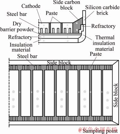
Fig. 1 Distribution of sampling points in lining material of electrolytic cell
Firstly, the samples were taken at the different sampling points in the cell by a pneumatic pick drilling. Then, the bath agglomerates stuck on the sample surface were cleaned up. After preparation the samples were put in the sample bags and placed in a constant-temperature (80 ��C) desiccator for 24 h. Finally, the dried sample was placed in a sample grounding machine for particle size <74 ��m for subsequent chemical and mineral analysis and research tests.
2.2 Cyanide analysis method
The cyanide content was measured by using the silver nitrate titration method [24] (the minimum detection concentration of cyanide is 0.25 mg/L). This method is to use a 0.01 mol/L silver nitrate standard solution to titrate the SPL leachate to which the indicator is added. The cyanide ion reacts with silver nitrate to form [Ag(CN)2]-, and an excess of silver ions reacts with the indicator to change the color from yellow to orange-red. The concentration of cyanide can be calculated based on the amount of silver nitrate at the titration end.
2.3 Leachable fluorides analysis method
The leachable fluorine content in the samples is analyzed by the ion selective electrode method in GB/T 15555.11 (the minimum detection concentration is 0.05 mg/L) [25]. And the instrument of the ion activity meter (PXSJ-216, Shanghai INESA Scientific Instrument Co., Ltd., China) is used for leachable fluorides analysis.
3 Results and discussion
It is found out from this study that the distribution of hazardous materials in the SPL is mainly influenced by the design of the lining, the cell life and the process parameters.
3.1 Fluoride footprint
Unlike the cell with low current intensity in the past, the life of the high-current cell with improved structure can reach more than 2000 days. More fluoride was accumulated into the lining material as the life of the cell increases. There is more or less fluoride diffusion in each part of the lining material in the cell after 2396 days. The average concentration of soluble fluoride in the cathode carbon block is 3422 mg/L, 3207 mg/L for the paste between the cathode carbon blocks, 3705 mg/L for the side carbon block, 1702 mg/L for the silicon carbide side block, 3077 mg/L for the side refractory material, 8315 mg/L for the dry barrier power, 2696 mg/L for the bottom refractory material, 1296 mg/L for the bottom insulation material and only 691 mg/L for the thermal insulating material (Fig. 2). The average concentration of fluoride in the cell is increased by 2000 mg/L compared to the low current intensity cell, which is related to the age of the cell and the amount of fluoride used.
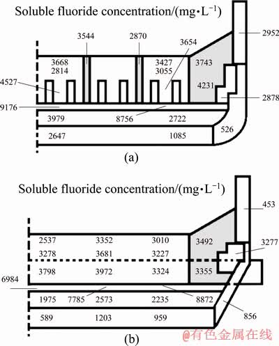
Fig. 2 Distributions of fluoride in longitudinal (a) and lateral (b) components of 350 kA cell
The results show that there is a large amount of fluorides in the spent cathode carbon block which are mainly in the form of sodium fluoride, calcium fluoride and cryolite (Fig. 3(a)). In the new cathode carbon block there exsits only carbonaceous material (Fig. 3(b)).
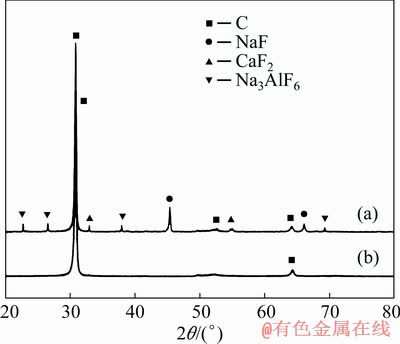
Fig. 3 XRD patterns of spent (a) and new (b) cathode carbon block
Most of the fluoride is concentrated in the carbon block and the dry barrier layer and the highest concentration of soluble fluoride in the lining appears below the cathode carbon block (Fig. 2).
From the top to the bottom of the cathode carbon block the fluoride distributes evenly, and there is no obvious concentration gradient. The fluoride concentration is slightly increased at the bottom of the cathode. But the concentration of soluble fluoride rises sharply in the dry barrier layer and reaches the peak in the entire cell. This means that a large amount of fluoride is enriched in this area. However, after passing through the dry barrier layer the concentration of soluble fluoride in the refractory material drops dramatically, which is even much lower than that in the cathode carbon block. Most of the fluoride is isolated in the dry barrier layer and it is difficult to penetrate further into the bottom lining materials. Only small amount of the fluoride can be detected in the bottom insulation material, which is much lower than that of other locations (Fig. 4).
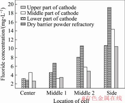
Fig. 4 Fluoride concentration gradient in vertical direction of cell lining
The cathode carbon block is the most important structural part of the aluminum reduction cell, which plays an important role in conducting current and undertaking high temperature molten salt. The cathode carbon blocks have been in direct contact with the metal and bath for several years and the fluoride in the electrolyte can gradually diffuse into this region. As the electrochemical reaction proceeds, the cathode carbon block is worn and cracked under the actions of erosion and stress in the molten aluminum metal. Moreover, fluoride can further penetrate into the lining material due to the presence of these cracks on the cathode surface. As time goes by, the fluoride content in the cathode carbon block has accumulated to a higher level.
Under the bottom of the cathode carbon block is a dry barrier layer in which the main components are Al2O3 and SiO2. When the fluorides diffuse to the dry barrier layer, these fluorides can react with the dry barrier materials in this area (Eqs. (1) and (2)), and the main reaction products are nepheline and albite [26]. Nepheline will exist in the form of a crystalline, and albite will form a sticky glass layer at the reaction site which will prevent further penetration of fluoride into the next layer. Moreover, the temperature at this location is also suitable for solid phase deposition and columnar crystal formation. Consequently, the fluoride gradually accumulates under the cathode carbon block, and the fluoride concentration reaches the peak in the entire electrolytic cell here.
6NaF(l)+3SiO2��2Al2O3(s)=3NaAlSiO4(s)+Na3AlF6(s) (1)
6NaF(l)+9SiO2��2Al2O3(s)=3NaAlSi3O8(s)+Na3AlF6(s) (2)
The results show that there is a large amount of fluorides and other substances in the spent dry barrier powder which are mainly in the form of sodium fluoride, calcium fluoride and nepheline (Fig. 5(a)). In the new dry barrier powder there exsit only Al2O3, SiO2 and SiO2��Al2O3 (Fig. 5(b)).
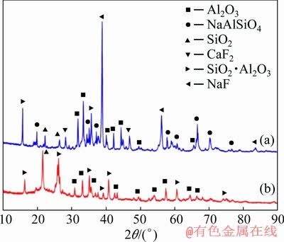
Fig. 5 XRD patterns of spent (a) and new (b) dry barrier powder
Further penetration of the fluoride can be hindered by the presence of the dry barrier layer due to the reactions so that the concentration of fluoride in the refractory brick and insulation material below the barrier layer is much lower (Fig. 6(a)).
However, in the actual tests and analysis, it is noticed that not so much fluorides can penetrate passing the dry barrier layer into the refractory. If too many fluorides infiltrate into the refractory material the severe corrosion will happen in this area. Corroded refractory materials cannot prevent the further penetration of the fluorides, which is one of the reasons for the reduction cell leakage. It can also be found that a very high fluoride concentration is detected in this area.
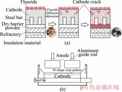
Fig. 6 Schematic diagram of fluoride diffusion into lining material (a) and W-shape wear pattern (b)
In the horizontal direction of the cell, the soluble fluoride concentration of the carbon block at the sidewall is slightly higher than that of the central carbon block. It is shown by TABEREAUX et al [27] that the highest cathode block erosion was often located under the anodes towards the sidewall of the cell and that the wear under some anodes was deeper than that under others. It is also found that there is almost no erosion in the center of the cell. This uneven cathode erosion leads to the most common erosion pattern observed in modern high-amperage prebaked anode cells called the W-shape or WW-shape wear pattern (Fig. 6(b)). The formation of the W-shape wear pattern is related to the current distribution and flow field in the cell. This corrosion pattern is more pronounced in high current intensity cells. In the areas where the corrosion pits are deep the higher concentrations of fluorides will be detected than that in other positions. Potholes can be easily found in the areas with a high degree of corrosion. This is helpful for the deposition and further diffusion of fluorides in this area. It can be supposed that the distribution of fluorides in the lining materials of the aluminum reduction cells is probably related to the current intensity and the flow status of the molten metal.
For the sidewall, the concentration of soluble fluoride in the side carbon block is higher than that in the side block of silicon carbide, the reason of which is possibly related to the side carbon block formation and baking process of the cells. The side wall includes the silicon carbide blocks and side carbon blocks. The carbon blocks are mainly from the ramming paste and baked during the baking process of the cells when lots of fluorides are absorbed into the ramming paste so that the side carbon blocks contain much more fluorides than in the silicon carbide blocks.
3.2 Cyanide footprint
NaCN can be formed and enriched in the lining material when N2 in the air reacts with the sodium-containing carbonaceous material in the cell:
1.5N2(g)+3Na(s)+3C(s)= 3NaCN(l)
 =-164.7 kJ (3)
It is found from the results of cyanide concentration analysis that cyanide does not distribute evenly in the lining of the cell (Fig. 7). The average cyanide concentration in the cathode carbon block is 5.2 mg/L and that in the paste between the cathode carbon blocks is 4.5 mg/L, while it is 61.1 mg/L in the side carbon block, 73.8 mg/L in the silicon carbide side block and 59.9 mg/L in the side refractory material, which means that side wall contains much higher cyanide concentration than in the cathode blocks at the cell bottom. The cyanide concentrations in dry barrier layer, bottom refractory material and bottom insulation material are 7.8, 5.2 and 3.7 mg/L, respectively. The cyanide concentration is as high as 73.3 mg/L in the side thermal insulating material like that in the side wall materials. The cyanide concentration in the cathode carbon block is reduced by 10 mg/L compared to the low current intensity cell, but the cyanide concentration in the side liner is significantly increased by 50 mg/L.
A very low level of cyanide is detected in the central region of the cell. However, the closer to the side wall the sample cell is, the higher the cyanideconcentration is in this sample cell. The concentration of cyanide in the side lining material can be several times higher than that in the cell center. It is found as well that cyanide also appears in non-carbonaceous materials. This means that cyanide is not fixed in the place where it is formed, but can be diffused and transferred into the lining material at other locations in the cell. It is found that the cyanide concentration in the silicon carbide side block and carbon block near the aluminum suction positions is also much higher than that in the other areas (Fig. 8).
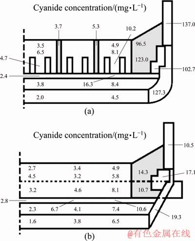
Fig. 7 Distribution of cyanide in longitudinal (a) and lateral (b) components of 350 kA Cell
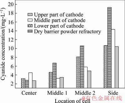
Fig. 8 Cyanide concentration gradient in horizontal direction of lining
The cyanide is produced by the reaction of the carbonaceous material with nitrogen in the air. This means that a high concentration of cyanide can be easily detected in a region where it is in contact with air and carbonaceous materials exist. Air can penetrate into the cell by the portholes in the side walls during aluminum reduction. Most air is infiltrated around the side walls of the cells and difficultly enters into the cell center. Therefore, high levels of cyanide appear in the side lining material of the reduction cells. In the same way, the cyanide concentration in the cell center is much lower due to lack of air.
The aluminum suction position is a special place for cyanide formation. The operation is carried out every day at this position, such as salvaging the carbon residue, measuring the levels of bath and aluminum metal, observing the operation state of the cells and extinguishing the anode effects. Frequent breaking of the crust and agitation of the bath and metal will cause a large amount of air to flow into this area, which creates good conditions for the formation of cyanide. That is why there is a high concentration of cyanide in the silicon carbide side block and the cathode carbon block near the suction position. The cyanide content in the lower side wall area is very low because it is immersed in the bath and metal and there is less chance to contact with air. So, the cyanide content in the lining is closely related to the place if air can enter into this part easily (Fig. 9).
According to the literature, when heated to 773 K, about 99.5% of cyanide in SPL was decomposed, when heated to 873 K, about 99.8% of cyanide was decomposed, and when heated to above 973 K, cyanide completely disappears. We find that cyanide is prone to the decomposition in an aerobic atmosphere. This means that although the infiltration of air in the cell causes the formation of cyanide, cyanide can also be decomposed in the presence of oxygen in the high temperature region. Therefore, a higher concentration of cyanide can be found in the side regions where the temperature is slightly lower and the air is more easily penetrated. However, cyanide is hardly found in the central portion of the cell where the temperature is high enough.
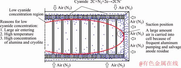
Fig. 9 Schematic diagram of cyanide distribution in lining of electrolytic cell
In addition, NaCN is unstable when Na3AlF6, Al2O3 and Na are simultaneously present in the reduction cell (1223 K) based on Eqs. (4) and (5):
1.5Na3AlF6(l)+1.5NaCN(l)+3Na(s)=1.5AlN(s)+9NaF(l)+1.5C(s) (4)
=-255.0 kJ/mol3Al2O3(s)+1.5NaCN(l)+3Na(s)=4.5NaAlO2(s)+1.5AlN(s)+1.5C(s) (5)
=-214.8 kJ/mol
The alumina feeders are located on the central axis of the electrolytic cell, so that the central portion of the cell is more enriched in alumina, which is prone to carrying out this decomposition reaction. Therefore, there is a lower cyanide concentration in this region while a higher cyanide distribution on the cell side where there is less Al2O3 concentration.
4 Conclusions
(1) Fluoride and cyanide in the SPL are the main factors affecting the environment, and the leachate from the long-term stacking SPL will contaminate the soil and groundwater nearby. The average concentration of fluoride in the electrolytic cell is increased by 2000 mg/L compared to the low current strength electrolytic cell, which is related to the age of the tank and the amount of fluoride salt used. Fluorides are usually concentrated in the cathode carbon block and dry barrier layer. The highest concentration of fluoride appears below the cathode carbon block, where the reaction between fluorides and dry barrier happens. The vitreous material forming in this reaction isolates most fluorides into this area and prevents them to further diffuse.
(2) The cyanide concentration in the cathode carbon block is reduced by 10 mg/L compared to the low current intensity cell, but the cyanide concentration in the side liner is significantly increased by 50 mg/L. This is related to the better tightness of the cell and the higher bath and metal levels. A large amount of cyanide is found in the side lining because of frequent air infiltration at the operating positions. The cyanide content in the various parts of the cell lining is closely related to the amount of air that can enter into this part. Cyanide mostly distributes near the side wall of the cell and it is not fixed in place where it forms, but can be diffused and transferred into other locations in the cell.
References
[1] Courbariaux Y, Chaouki J, Guy C. Update on spent potliners treatments: Kinetics of cyanides destruction at high temperature [J]. Industrial and Engineering Chemistry Reseacrch, 2004, 43: 5828-5837.
[2] ZHU Jun, XUE Ji-lai, ZHANG Ya-nan, LI Xiang, CHEN Tong. Ambient electrical conductivity of carbon cathode materials for aluminum reduction cells [J]. Transactions of Nonferrous Metals Society of China, 2015, 25: 3753-3759.
[3] Sleap S B, Turner B D, Sloan S W. Kinetics of fluoride removal from spent pot liner eachate (SPLL) contaminated groundwater [J]. Journal of Environmental Chemical Engineering, 2015, 3: 2580-2587.
[4] Palmieri M J, Andrade L F, Trento M V C, de Faria E. Cytogenotoxic effects of spent pot liner (SPL) and its main components on human leukocytes and meristematic cells of Allium cepa [J]. Water Air and Soil Pollution, 2016, 227: 1-10.
[5] Andrade L F, Davide L C, Gedraite L S, Campos J M S, Azevedo H. Genotoxicity of SPL (spent pot lining) as measured by tradescantia bioassays [J]. Ecotoxicology and Environmental Safety, 2011, 74: 2065-2069.
[6] Andrade L F, Davide L C, Gedraite L S. The effect of cyanide compounds, fluorides, aluminum, and inorganic oxides present in spent pot liner on germination and root tip cells of Lactuca sativa [J]. Ecotoxicology and Environmental Safety, 2009, 73: 626-631.
[7] Hollywell G, Breault R. An overview of useful methods to treat, recover, or recycle spent pot lining [J]. JOM, 2013, 65: 1441-1451.
[8] Li Nan, Xie Gang, Wang Zu-xu, Hou Yan-qing, Li Rong-xing. Recycle of spent pot-lining with low carbon grade by floatation [J]. Advanced Materials Research, 2014, 881: 1660-1664.
[9] YU Da-wei, Paktunc D. Carbothermic reduction of chromite fluxed with aluminum spent potlining [J]. Transactions of Nonferrous Metals Society of China, 2019, 29: 200-212.
[10] Mazumder B, Devi S R. Conversion of byproduct carbon obtained from spent pot liner treatment plant of aluminum industries to blast furnace tap hole mass [J]. Journal of Applied Chemistry, 2013, 3: 24-35.
[11] Yu D, Chattopadhyay K. Numerical simulation of copper recovery from converter slags by the utilisation of spent potlining (SPL) from aluminium electrolytic cells [J]. Canadian Metallurgy Quarterly, 2016, 55: 251-261.
[12] Lisbona D F, Steel K M. Recovery of fluoride values from spent pot-lining: Precipitation of an aluminium hydroxyfluoride hydrate product [J]. Separation and Purification Technology, 2018, 61: 182-192.
[13] Birry L, Leclerc S, Poirier S. The LCL & L process: A sustainable solution for the treatment and recycling of spent potlining [J]. Light Metal, 2016: 467-469.
[14] Lisbona D F, Somerfield C, Steel K M. Leaching of spent pot-lining with aluminium nitrate and nitric acid: Effect of reaction conditions and thermodynamic modelling of solution speciation [J]. Hydrometallurgy, 2013, 134-135: 132-143.
[15] ZHANG Hong-liang, YANG Shuai, LI Jie. Relationship between alumina mixing characteristics and feeder configurations in aluminum reduction cells [J]. Transactions of Nonferrous Metals Society of China, 2017, 27: 2512-2520.
[16] FANG Zhao, WU Xiao-lei, YU Juan, LI Lin-bo, ZHU Jun. Penetrative and migratory behavior of alkali metal in different binder based TiB2�CC composite cathodes [J]. Transactions of Nonferrous Metals Society of China, 2014, 24: 1220-1230.
[17] Shi Zhong-ning, Li Wei, Hu Xian-wei, Ren Bi-jun, Gao Bing-liang, Wang Zhao-wen. Recovery of carbon and cryolite from spent pot lining of aluminium reduction cells by chemical leaching [J]. Transactions of Nonferrous Metals Society of China, 2012, 22: 222-227.
[18] Saterlay A J, Hong Q, Compton R G, Clarkson J. Ultrasonically enhanced leaching: Removal and destruction of cyanide and other ions from used carbon cathodes [J]. Ultrasonics Sonochemistry, 2000, 7: 1-6.
[19] Pong T K, Adrien R J, Besida J, O��Donnell T A, Wood D G. Spent potlining-A hazardous waste made safe [J]. Process Safety and Environmental Protection, 2000, 78: 204-208.
[20] Brooks D G, Cutshall E R, Banker D B, Strahan D F. Thermal treatment of spent pot lining in a kiln [J]. Light Metal, 1992: 1044-1048.
[21] Li Wang-xing, Chen Xi-ping. Development status of processing technology for spent pot lining in China [J]. Light Metal, 2010: 1064-1066.
[22] Peterson R W, Blayden L C, Martin E S. Formation and distribution of cyanide in the lining of aluminum reduction cells [M]. Springer International Publishing, 2016.
[23] Silveira B I, Dantas A E, Blasquez J E, Santos R K P. Characterization of inorganic fraction of spent potliners: Evaluation of the cyanides and fluorides content [J]. Journal of Hazardous Materials, 2002, 89: 177-183.
[24] GB/T15555.11��1995. Solid waste-Determination of fluoride-Ion selective electrode method [S].
[25] GB7486��1987. Water quality-Determination of cyanide. Part 1: Determination of total cyanide [S].
[26] Siljan O J, Schoning C, Grande T. State-of-the-art alumino-silicate refractories for Al electrolysis cells [J]. JOM, 2002, 54: 46-55.
[27] Tabereaux A T, Brown J H, Eldridge I J, Alcorn T R. Erosion of cathode blocks in 180 kA prebake cells [J]. Light Metal, 1999: 999-1004.
������1,2��л��׳1,2���� ΰ1,2���Ժ���1,2,3
1. �����Ƽ���ѧ ����ұ���¼��������ص�ʵ���ң����� 100083��
2. �����Ƽ���ѧ ұ������̬����ѧԺ������ 100083��
3. Department of Materials Science and Engineering, The University of Utah, Salt Lake City, Utah 84112, USA
ժ Ҫ�������ϲ۳�(SPL)���京�д��������Է�����������綾�軯�������ΪΣ�չ���������������2396���350 kA�������з�������軯��ķֲ�״�����м��������о��ϲ۳��ж������ʵ��㼣��ʴ�������о������������������Ҫ����������̿��������·��ĸ�ʽ�����ϲ��У�����������ڴ��������״̬������ء��軯��Ũ���ڵ����в�λ�ýϵͣ�����ڸ�Ũ�ȵ��軯�����������ڸ�����Ŀ�����������ء�
�ؼ��ʣ�����⣻�ϲ۳ģ�������軯��㼣
(Edited by Bing YANG)
Foundation item: Project (2019YFC1908400) supported by the National Key Research and Development Program of China; Project (2018BDE02050) supported by the Key Research and Development Program of Ningxia Hui Autonomous Region, China; Project (2302018FRF-TP-18-095A1) supported by the Fundamental Research Funds for the Central Universities, China; Project (2018-XY-14) supported by the Special Funds for Scientific and Technological Consultation of Academicians, China
Corresponding author: Hong-liang ZHAO; Tel: +86-18618336024; E-mail: zhaohl@ustb.edu.cn
DOI: 10.1016/S1003-6326(20)65353-5

