Microstructure transformation of carbon nanofibers during graphitization
¿¥‘¥∆⁄øØ£∫÷–π˙”–…´Ω Ù—ß±®(”¢Œƒ∞Ê)2008ƒÍµ⁄5∆⁄
¬€Œƒ◊˜’þ£∫’≈”¬ Ã∆‘™∫È ¡÷¡ºŒ‰ ’≈∂˜¿⁄
Œƒ’¬“≥¬Î£∫1094 - 1099
Key words£∫carbon nanofibers; microstructure; graphitization; mechanism
Abstract: The microstructures of vapor-grown carbon nanofibers(CNFs) before and after graphitization process were analyzed by high resolution transmission electron microscopy(HRTEM), Raman spectroscopy, X-ray diffractometry(XRD), near-edge-X-ray absorption fine structure spectroscopy(NEXAFS) and thermogravimetric analysis(TGA). The results indicate that although non-graphitized CNFs have the characteristics of higher disorder, a transformation is found in the inner layer of tube wall where graphite sheets become stiff, which demonstrates the characteristics of higher graphitization of graphitized CNFs. The defects in outer tube wall disappear because the amorphous carbon changes to perfect crystalline carbon after annealing treatment at about 2 800 °Ê. TGA analysis in air indicates that graphitized CNFs have excellent oxidation resistance up to 857 °Ê. And the graphitization mechanism including four stages was also proposed.

ZHANG Yong(’≈ ”¬)1, TANG Yuan-hong(Ã∆‘™∫È)1, 2, LIN Liang-wu(¡÷¡ºŒ‰)1, ZHANG En-lei(’≈∂˜¿⁄)1
1. College of Materials Science and Engineering, Hunan University, Changsha 410082, China;
2. State Key Laboratory of Power Metallurgy, Central South University, Changsha 410083, China
Received 18 May 2007; accepted 1 April 2008
Abstract: The microstructures of vapor-grown carbon nanofibers(CNFs) before and after graphitization process were analyzed by high resolution transmission electron microscopy(HRTEM), Raman spectroscopy, X-ray diffractometry(XRD), near-edge-X-ray absorption fine structure spectroscopy(NEXAFS) and thermogravimetric analysis(TGA). The results indicate that although non-graphitized CNFs have the characteristics of higher disorder, a transformation is found in the inner layer of tube wall where graphite sheets become stiff, which demonstrates the characteristics of higher graphitization of graphitized CNFs. The defects in outer tube wall disappear because the amorphous carbon changes to perfect crystalline carbon after annealing treatment at about 2 800 °Ê. TGA analysis in air indicates that graphitized CNFs have excellent oxidation resistance up to 857 °Ê. And the graphitization mechanism including four stages was also proposed.
Key words: carbon nanofibers; microstructure; graphitization; mechanism
1 Introduction
Since the discovery of carbon nanotubes (CNTs) by IIJIMA[1], carbon fibers in nanometer scale which are called carbon nanofibers (CNFs) have arouse worldwide research interest. It°Øs well known that carbon fibers possess various excellent properties: low density, high strength and modulus, high corrosion resistance, high thermal and electrical conductivity and so on. Therefore, they have been used as materials of sport equipments and aircraft instruments, etc[2]. Recently, CNFs have shown great potential applications in the fields of composites[3], electronic devices[4-5], hydrogen storage[6] and fuel cells[7] due to their excellent physical and chemical properties. In general, CNFs have two kinds of structures with the hollow and solid core[7-8]. The outer diameter of CNFs ranges from 10 to 500 nm[9], which is different from that of CNTs (~10 nm). On the other hand, the crystallization degree of CNFs is lower than that of CNTs. Numerous methods including floating catalyst chemical vapor deposition (CVD)[10], laser evaporation [11], heat evaporation[8], plasma-enhanced CCVD[12] and electrospinning[13] for synthesis of CNFs have been developed. Among the variety of methods, the floating catalyst chemical vapor deposition which uses catalyst floating in a reactor is simple and efficient for large scale synthesis of CNFs at low cost and will be the potential
candidate for a commercial-scale process.
Non-graphitized CNFs must be purified to remove the impurities such as metal particles and other carbon material. Its application has been limited because of poor graphitization and more defects in the fibers. It is near temperature of 3 000 °Ê that the complete graphitization of carbon products can be achieved by heat treatment. However, the properties (especially the electrical and mechanical properties) of CNFs after graphitization are better than those of non-graphitized CNFs in evidence. For example, the tensile strength of Pyrograf¢ÒCNFs[3] after graphitization (Applied Science Inc, USA), increases from 2.7 GPa to 7.0 GPa and elastic modulus from 400 GPa to 600 GPa, which will greatly improve the strength of carbon/carbon composite. The volume resistivity reduces from 1 000 ¶ÃW?cm to 55 ¶ÃW?cm. Moreover, amorphous carbon will decrease greatly through heat treatment so that the number of active carbon atoms on CNFs surface will reduce to improve the oxidation resistance[14]. Graphitized CNFs have been successfully used in a Li-ion battery and double layer capacitor systems[15].
It is very important to analyze the changes of microstructure of CNFs before and after graphitization in order to apply them in various kinds of nanofibers reinforced composites and other novel materials as func- tional fillers. In this work, structural characteristics of the CNFs before and after graphitization are investigated by HRTEM, Raman spectroscopy, XRD, and near-edge X-ray absorption fine structure spectroscopy (NEXAFS), and TGA. Especially, NEXAFS used to study CNFs in detail is not reported in previous work. The technique uses a local atomic probe, not dependent on large-range order, which makes it suitable to study the amorphous and micro-crystalline material. The most interesting research is that NEXAFS can distinguish the sp2 or sp3 hybridized carbon materials[16]. In the end, the graphitization mechanism including four stages was also proposed.
2 Experimental
The CNFs used in this study were purchased from the Gina New Materials Corporation in Shenyang, China, and fabricated at the temperature of 1 373®C1 473 K in the presence of sulfur by the floating catalyst CVD method with a horizontal reactor using benzene as carbon source, ferrocene as catalyst precursor and hydrogen as carrier gas. The as-grown CNFs were purified to remove the Fe catalyst particles and other organic compounds. The purified CNFs were then heat-treated at 2 800 °Ê under inert gas protection for 30 min.
Raman spectroscopy analysis was conducted on Labram-010 spectrometer (Jobin Yvon) with the excitation source wavelength of 632.832 nm by a helium-neon laser, a spot size of 3 ¶Ãm in diameter and a power of 2.4 mW. The XRD patterns were recorded in an X-ray diffractometer (Simens D5000) at room temperature, using Cu K¶¡ radiation with wavelength of 1.54 ?. A JEM-3010 (JEOL, Japan) HRTEM operating at 300 kV was used for the sample observation.
The C K-edge NEXAFS of CNFs before and after graphitization were measured in the Soft X-ray Magnetic Circular Dichroism (SXMCD) beamline with an electron beam (e-beam) energy range of 100-1 000 eV and average beam current of 100-300 mA at the National Synchrotron Radiation Laboratory (NSRL), University of Science and Technology of China. At the C K-edge, the energy resolution of the MCD was about 1 000 (75°¡20 micron slit setting). The beam spot size at normal incidence was 3 mm°¡1 mm. The samples of CNFs were riveted by conductive adhesion onto a metallic holder and load in a chamber maintained in a background pressure of about 10-9 Pa. The sample can rotate on the plane of incidence of the beam. The NEXAFS were recorded at room temperature in surface-sensitive total electron yield (TEY) mode with wavelength scanning of 0.2 eV. Thermogravimetric analysis (TGA) was carried out in air atmosphere with a heating rate of 2 °Ê/min by thermogravimetric analyzer (STA449C, Netzsch, German).
3 Results and discussion
3.1 TEM analysis
Fig.1 shows a typical TEM micrograph of carbon nanofibers fabricated by CVD. Most of the carbon nano- fibers are straight with hollow cores which are typically tubular-like, and a few of slid nanofibers can also been found. The metal catalyst particles are not observed in the two samples. The nanofibers have quite thick wall sand wide diameter distribution, approximately 5-36 nm in internal diameter and 30-120 nm in external diameter. Compared with Fig.1(a), the tube walls of graphitized CNFs shown in Fig.1(b) are smooth without amorphous carbonaceous and visible defects. But it can be seen from the image that the length of graphitized CNFs becomes shorter than that of non-graphitized CNFs. Some single nanofibers break into several fractions and the cross section can be seen clearly, which may be attributed to the high temperature treatment.
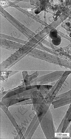
Fig.1 TEM images of non-graphitized (a) and graphitized (b) CNFs
The HRTEM images (Fig.2) show that the tube wall of the CNF is composed of two layers: the inner layer(the sharp dark line), grown by continuous curled raphite sheets, and the outer layer, grown by pyrolyzed carbon deposited on the fiber surface. The HRTEM images (Fig.2) also show the (002) lattice fringes of CNFs. Graphite sheets are parallel to the fibers-axis, which is a typical structure of tubular-like CNFs. The lattice fringes of non-graphitized CNFs are discontinuous, little distorted and defective, and the spacing between graphite sheets is 0.352 nm (Fig.2(a)). Fig.2(b) shows the lattice fringes of the wall of graphitized CNFs.
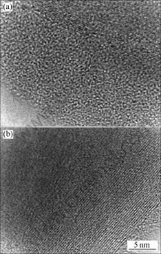
Fig.2 HRTEM images of lattice fringes: (a) Non-graphitized CNFs; (b) Graphitized CNFs
Compared with the structure of non-graphitized CNFs, great changes have taken place in the inner layer where graphite sheets become stiff and quite perfect, and amorphous carbon layer in outer-layer becomes thinner from 15 nm to 2 nm. These structural transformations are attributed to the high mobility of carbon atoms at high temperature to eliminate the defects in graphite sheets and modify the tube wall. The spacing between graphite sheets is 0.342 nm, which is smaller than that of non-graphitized CNFs. The increase of activation energy due to the high temperature heat-treatment not only makes the graphite sheets in inner layer arranging in order and more continuous, but also promotes the amorphous crystalline carbon in outer layer growing up and the orientation of disorganized hexagonal surface of crystallite becomes ordered. At the same time, hexagonal surface of crystalline becomes more adjacent to each other. The higher activation energy orders a little amorphous carbon into large aromatic sheets, so the outer layer becomes thin and the structure of CNFs tends to ideal graphite crystal. According to Arrhenius relation, it yields
![]()
where R is the ideal gas constant, Q is the activation energy of the phase transformation, x0 is the pre- exponential factor and T is the temperature. It can be seen that the mole fraction of graphite (xG) increases while the T rises up. So these results just can explain the feature of the amorphous carbon layer to become thin.
3.2 Raman spectra analysis
Fig.3 shows the Raman spectra of non-graphitized and graphitized CNFs respectively, in a range of Raman shift from 0 to 3 000 cm-1. It is well known that the first order Raman spectrum of CNFs is constituted of D and G bands. The D band corresponds to the defect-induced Raman band involving phonons near the K Brillouin zone boundary which has a high sensitivity to disorder in carbon materials, while the G band in cause of disorder of micro-crystal graphite is usually assigned to Brillouin zone center phonons of E2g symmetry.

Fig.3 Raman spectra of non-graphitized (a) and graphitized (b) CNFs
The first order Raman spectrum typically between 1 000 cm-1 and 1 800 cm-1 is composed of two main peaks, at around 1 340 cm-1 and 1 590 cm-1 for the non- graphitized CNFs, and at 1 340 cm-1 and 1 582 cm-1 for the graphitized CNFs, respectively. The peaks at around 2 640 cm-1 (Fig.3(a)) and 2 658 cm-1 (Fig.3(b)) are called as the second-order (2D) peaks. Furthermore, the weak band of 2 930 cm-1 in the second-order Raman band for non-graphitized CNFs is observed. It is suggested that the peak is the combination band of 1 340 cm-1 and 1 590 cm-1.
The root of Raman peak for non-graphitized CNFs is very wide and even conjoint. The shape of peak for graphitized CNFs is quite sharp. Therefore, it is possible that a small amount of amorphous carbon deposited on the surface of non-graphitized nanofibers induces a large intensity of the D-band, and these deposits are annealed out through the graphitization process. Generally, the ratio of the integrated intensity of D peak to G peak is 0.88 for non-graphitized CNFs and 0.37 for graphitized CNFs, respectively, denoted by R = ID/IG, which depends on the in-plane graphitic crystallite size (La). ID and IG are proportional to the number of the scattering disordered and ordered sp2 bonding carbon atoms in illuminated area. According to the equation given by KNIGHT[17], La= 4.4°¡(ID/IG)-1, La is calculated to be about 5 nm for non-graphitized CNFs and 11 nm for graphitized CNFs. Therefore, we consider that the degree of disorder for non-graphitized CNFs caused by the defects and amorphous carbon becomes higher, and graphite micro-crystallite grows up through heat treatment, which agrees with WANG°Øs results[18].
3.3 XRD analysis
The XRD result (Fig.4(a)) also shows the structural feature of non-graphitized CNFs. The sharp splitting peak of (002) reflection at the small scattering angle (2¶» = 25.3?) indicates that part of the graphitization degree of CNF is rather complete. However, the wider root of the (002) diffraction trace shows the characteristics of the amorphous carbon and the disordered graphite sheets. Fig.4(b) gives the structure features of graphitized CNFs. Its higher sharp peak of (002) reflection moving to higher angles (26.01?) shows that the graphitization degree of the sample increases, and the peaks of (100) and (101) reflections near the scattering angle of 43?, and (004) and (110) reflections respectively near 54? and 78? also give evidence of high graphitization characteristics. In term of Scherrer equation, it yields
![]()
where Lc is the average crystalline size along the crystallographic c-axis, ¶» is the angle of diffraction, ¶À is the incident ray wavelength, k = 0.89 is Scherrer constant, and ¶¬ is the value of the half height width of the diffraction peak. The average crystalline sizes (Lc) of CNFs before and after graphitization are calculated to be 2.9 nm and 6.0 nm, respectively. It is demonstrated that graphite micro-crystallite grows up and the number of graphite sheets also increases. Moreover, from the XRD data the interlayer spacings d(002) before and after graphitization are 0.352 nm and 0.342 nm, which are consistent with the HRTEM results.
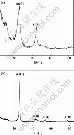
Fig.4 XRD patterns of non-graphitized (a) and graphitized (b) CNFs
3.4 NEXAFS spectrum analysis
Fig.5(a) shows the C K-edge NEXAFS spectra of CNFs before and after graphitization. Resonances at 285.2 eV in the total electron yield(TEY) of two CNFs are attributed to C 1s to ¶–* transition, which indicates the presence of unsaturated carbon-carbon interactions (sp2 bonding)[19]. It is noticed that the intensity of the ¶–* peaks increases slightly after graphitization, which may be related to the increase of the number of C sp2 bonds. A small peak occurs in the 287-290 eV region for non- graphitized CNFs that can be assigned to C°™O or C°™H bond[16], but the peak is very weak and even disappears in the graphitized CNFs. Fig.5(b) shows the O K-edge NEXAFS spectra of CNFs before and after graphitization. The NEXAFS signal from the non-graphitized CNFs is characterized by one pre-edge feature in the photon energy range of 529-535 eV and other feature in the photon energy range of 535-545 eV[20], which demonstrates that oxygen absorption is presented in the non-graphitized CNFs due to the roughness surface and defects in outer-layer. A similar feature is hardly detected in graphitized CNFs. It can be seen from Fig.5(a) that the C°™C ¶“* resonance peak is at 291.4 eV in both non-graphitized CNFs and graphitized CNFs. But the peak of the non-graphitized CNFs is almost a smooth curve unlike that of the graphitized CNFs, which may be attributed to the nanometer-scale. A broad (¶“+¶–) transition from 300-320 eV is also observed. The peak of graphitized CNFs is very similar to that of the highly oriented pyrolytic graphite (HOPG)[21]. From these results, it is found that the graphitization process has a great effect on the variation of microstructure for the CNFs.
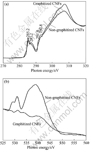
Fig.5 C K-edge absorption spectra (a) and O K-edge absorption spectra (b) of CNFs before and after graphitization
3.5 Oxidation resistance of CNFs
Fig.6 shows the TGA curves of CNFs before and after graphitization. The non-graphitized CNFs show a lower onset temperature and faster rate for the oxidation in comparison with graphitized CNFs. The temperature of the maximum rate of oxidation (peak in the DSC curve) is 617 °Ê for the non-graphitized CNFs, and 857 °Ê for the graphitized CNFs. These indicate that the quality of the non-graphitized CNFs is poor as compared with the graphitized CNFs. It is well known that the greater the number of active carbon atoms on CNFs surface, the easier the carbon material will be oxidized [14]. In addition, we believe that the oxidation-resistance is consistent with the proposed structures of CNFs, in which aromatic bonding dominates and dangling bonds are minimal[1]. The amorphous carbon on the outer-layer of CNFs is mostly removed to reduce active sites through heat treatment. On the other hand, the high thermal stability of CNFs is partially due to the defect-healing effect induced by high graphitization temperature.
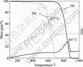
Fig.6 TGA curves of CNFs before and after graphitization (Dotted lines (a) for non-graphitized CNFs, solid lines (b) for graphitized CNFs)
4 Graphitization mechanism of CNFs
Here, we propose the graphitization mechanism including four stages. Fig.7 shows the schematic diagram of transformations in tube wall of CNFs during the graphitization process. The graphite structure in inner- layer of the non-graphitized CNFs is rather perfect, just a little defects exist. The amorphous carbon layered over the inner-layer of tube wall is composed of a mixture of graphite micro-crystallite with an oriented turbostratic structure and diamond-type bound carbon that is difficult to be graphitized. In the first stage (Fig.7(a)), the random oriented graphite micro-crystallite is associated edge to edge and face to face in parallel. However, the graphite micro-crystallite is separated by tilt and twist boundaries where defects are gathered. At stage 2 (Fig.7(b)), the graphite micro-crystallite coalesces face to face into distorted columns and the lateral coalescence is inhibited by misoriented single graphite micro-crystallite. This stage ends when the graphite micro-crystallite orients with respect to the fiber-axis. The CNFs don°Øt grow in diameter but the thickness of the graphite stacks moderately increases. At stage 3 (Fig.7(c)), the disappearance of the misoriented single graphite micro- crystallite permits the adjacent columns to coalesce so as to produce longer distorted fringes (in the lattice fringe images (Fig.2(b)) corresponding to larger distorted aromatic layers. At the same time, the spacing between graphite sheets reduces slightly. ROUZAUD et al[22] considered that the process corresponds to the association of little graphite crystal face to face and to the release of interlayer defects between the little graphite crystals. Fig.7(d) shows that at the end of graphi- tization, the thickness of the amorphous carbon decreases, while the graphite sheet increases in inner-layer tube wall. All distortions are annealed and in-plane defects are successively removed, (002) lattice fringes are stiff and perfect (Fig.2(b)). The crystal growth may thus begin and the graphite crystallite size (La or Lc) increases. The spacing between graphite sheets reduces from 0.352 to 0.342 nm finally.

Fig.7 Schematic diagram of graphitization mechanism of CNFs (small stripes represent turbostratic graphite micro-crystallite and dots represent diamond-type bond carbon)
5 Conclusions
The defects, amorphous carbon and metal-catalyst particles in the as-grown CNFs will have great effects in the practical application of CNFs greatly. The content of non-crystalline carbon in the non-graphitized CNFs decreases greatly and the degree of graphitization improves obviously after heat treatment at 2 800 °Ê according to the HRTEM, Raman, XRD and NEXAFS analyses. The temperature of oxidation-resistance increases greatly up to 857 °Ê due to the changes of graphitization on the microstructure of CNFs. The four stages graphitization mechanism of CNFs is proposed. The oriented turbostratic graphite micro-crystalline in the amorphous carbon forms large aromatic sheets along fiber-axis during the heat treatment, which makes (002) lattice fringe ordered and tend to ideal graphite, and the small amount of amorphous carbon is almost completely removed in the outer tube wall. At the same time, the defects in the inner tube wall are healed up owing to the shift of carbon atoms.
References[1] IIJIMA S. Helical microtubules of graphite carbon [J]. Nature, 1991, 354: 56-58.
[2] EDIE D D. The effect of processing on the structure and properties of carbon fibers [J]. Carbon, 1998, 36(4): 345-362.
[3] HAMMEL E, TANG M, TRAMPERT T, SCHMITT K, MAUTHNER A, EDER, PSCHKE P. Carbon nanofibers for composite applications [J]. Carbon, 2004, 42: 1153-1158.
[4] CHEN C F, LIN C L, WANG C M. Field emission from aligned carbon nanofibers grown in situ by hot filament chemical vapor desposition [J]. Appl Phys Lett, 2003, 82(15): 2515-2517.
[5] SMITH R C, CAREY J D, POA C H P, COX D C, SILVA S R P. Electron field emission from room temperature grown carbon nanofibers[J]. J Appl Phys, 2004, 95(6): 3153-3157.
[6] LUEKING A D, YANG R T, RODRIGUEZ N M, BAKER R T K. Hydrogen storage in graphite nanofibers: Effect of synthesis catalyst and pretreatment conditions [J]. Langmuir, 2004, 20: 714-721.
[7] ZOU G F, ZHANG D W, DONG C, LI H, XING K, FEI L F, QIAN Y T. Carbon nanofibers: Synthesis, characterization, and electro- chemical properties [J]. Carbon, 2006, 44: 828-832.
[8] TANG Y H, ZHANG Y. Synthesis and growth mechanism of diamond-like carbon nanowires [J]. The Chinese Journal of Nonferrous Metals, 2004, 14(9): 1461-1464. (in Chinese)
[9] ENDO M, TAKEUCHI K, HIRAOKA T, FURUTA T, KASAI T, SUN X, KIANG C H, DRESSELHAUS M S. Stacking nature of graphene layers in carbon nanotubes and nanofibers [J]. J Phys Chem Solids, 1997, 58(11): 1702-1712.
[10] CI L J, LI Y, WEI B Q, LIANG J, XU C, WU D. Preparation of carbon nanofibers by the floating catalyst method [J]. Carbon, 2000, 38(14): 1933-1937.
[11] VANDER W R L, BERGER G M, TICICH T M. Carbon nanotubes synthesis in a flame with independently prepared laser-ablated catalyst particles [J]. J Nanosci Nanotech, 2003, 3(3): 241-245.
[12] MERKULOV V I, MELECHKO A V, GUILLORN M A, SIMPSON M L, LOWNDES D H, WHEALTON J H, RARIDON R J. Controlled alignment of carbon nanofibers in a large-scale synthesis process [J]. Appl Phys Lett, 2002, 80(25): 4816-4818.
[13] WANG Y, SANTIAGO-AVILES J J. Large negative magnetoresistance and two-dimensional weak localization in carbon nanofibers fabricated using electrospinning [J]. J Appl Phys, 2003, 94(3): 1721-1727.
[14] PARK C, BAKER R T K. Catalytic behavior of graphite nanofiber supported nickel particles(3): The effect of chemical blocking on the performance of the system [J]. J Phys Chem B, 1999, 103: 2453-2459.
[15] ENDO M, KIM Y A, HAYASHI T, MATUSHITA T, MIYASHITA K, DRESSEL-HAUS M S. Vapor grown carbon fibers (VGCFs): Basic properties and their battery applications [J]. Carbon, 2001, 39: 1287-1297.
[16] COFFMAN F L, CAO R, PIANETTA P A, KAPOOR S, KELLY M, TERMINELLO L J. Near-edge X-ray absorption of carbon materials for detemining bond hybridization in mixed sp2/sp3 bonded material [J]. Appl Phys Lett, 1996, 69: 568-571.
[17] MATTHEWS M J, PIMENTA M A, DRESSELHAUS G. Origin of dipersive effects of the Raman D band in carbon materials [J]. Phys Rew B, 1999, 59(10): R6585-6588
[18] WANG Y, SERRANO S, SANTIAGO-AVILES J J. Raman characterization of carbon nanofibers prepared using electrospinning [J]. Synthetic Metals, 2003, 138: 423-427.
[19] TANG Y H, ZHANG P, KIM P S, SHAM T K, HU Y F, SUN X H. Amorphous carbon nanowires investigated by near-edge-X-ray absorption fine structures [J]. Appl Phys Lett, 2001, 79(23): 3773-3775.
[20] MA Y, CHEN C T, MEIGS G, RANDALL K, SETTE F. High-resolution K-shell photoabsorption measurements of simple molecules [J]. Phys Rev A, 1991, 44(3): 1848-1858.
[21] BANERJEE S, HEMRAJ-BENNY T, BALASUBRAMANIAN M. Surface chemistry and structure of purified, ozonized, multiwalled carbon nanotubes probed by NEXAFS and vibrational spectroscopies [J]. Chem Phys Chem, 2004, 5: 14165-1422.
[22] ROUZAUD J N, OBERLIN A. Structure, microtexture and optical properties of anthracene and saccharose-base carbons [J]. Carbon, 1989, 27(4): 517-529.
Corresponding author: TANG Yuan-hong; Tel: +86-731-8821778; E-mail: yhtang@hnu.cn

