
Numerical simulation of facet dendrite growth
CHEN Zhi(陈 志)1, CHEN Chang-le(陈长乐)1, HAO Li-mei(郝丽梅)2
1. Department of Applied Physics, Shannxi Key Laboratory of Condensed Matter Structures and Properties,
Northwestern Polytechnical University, Xi’an 710072, China;
2. Department of Basic Courses, Xi’an University of Science and Technology, Xi’an 710054, China
Received 8 October 2007; accepted 31 March 2008
Abstract: Numerical simulation based on phase field method was performed to describe the solidification of silicon. The effect of anisotropy, undercooling and coupling parameter on dendrite growth shape was investigated. It is indicated that the entire facet dendrite shapes are obtained by using regularized phase field model. Steady state tip velocity of dendrite drives to a fixed value when γ≤0.13. With further increasing the anisotropy value, steady state tip velocity decreases and the size is smaller. With the increase in the undercooling and coupling parameter, crystal grows from facet to facet dendrite. In addition, with increasing coupling parameter, the facet part of facet dendrite decreases gradually, which is in good agreement with Wulff theory.
Key words: phase field method; facet dendrite; anisotropy; undercooling; tip velocity
1 Introduction
Phase field method has been used to simulate the complicated pattern formation during crystal growth, and different dendrite patterns are obtained successfully[1-4]. The main problem in modeling crystal growth is how to solve moving boundary problem, which requires a specific treatment at the discontinuous solid/liquid interface. The merits of phase field method are that interface curvature, anisotropy and kinetics effects are implicitly incorporated in the phase field equation, and that the explicit tracking of the interface is unnecessary[5-6]. In the early application many problems occur, and the significant problem is that interface thickness must be much smaller than that of thermal boundary to meet with sharp interface limit, which makes it difficult to simulate dendrite shape. The interface kinetics coefficient in Karma and Rappel model can be eliminated by selecting and using appropriate parameters, and interface thickness can be released to an order of microstructures, then phase field method makes great progress[5,7-9]. The equilibrium condition at the interface is given by the Gibbs-Thomson equation:
(W+Wφφ)/R(φ)=fL-fS=1-15γcos(4φ) (1)
where W is solid/liquid interface energy, γ is anisotropy parameter, φ is the angle of the direction normal to the interface and the horizontal axis, R(φ) is the curvature radius of interface, fS and fL are free energy densities of the solid and liquid phases, respectively. When γ<1/15, namely, weak anisotropy, both sides of the equation are always positive and a smooth and convex non-faceted crystal is stable. Conversely, when γ>1/15, namely, strong anisotropy, the left hand side of the equation appears negative within the interface missing orientations, as a result, it is difficult to model dendrite growth. Since 2001, the problem has been solved through regularizing phase field model[10-14].
In this work, a new regularizing phase field model is presented based on EGGLESTON and KIM’s model. The entire dendrite growth shape of silicon is calculated, and the effect of anisotropy parameter, undercooling and coupling parameter is examined in detail.
2 Phase field model
These Wulff equilibrium crystal shapes[15-16] at various anisotropy values are given in Fig.1. When γ<1/15, crystal shape is smooth and continuous; on the contrary, when γ>1/15, it occurs in discontinuous concave similar to “ears”, and these “ear” parts increase with increasing anisotropy value. In order to simulate dendrite growth in strong anisotropy, these “ears” must be removed. The interface energy within the missing orientations has been regularized by EGGLESTON and KIM, as follows:
 (2)
(2)
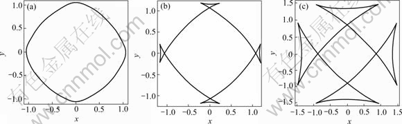
Fig.1 Equilibrium crystal shapes at various anisotropy values: (a) γ=0.05; (b) γ=0.15; (c) γ=0.35
where i=0-3, φm is the corner angle of the equilibrium shape or first missing orientation, and it is calculated through
 (3)
(3)
A new regularized phase field equations[17] can be obtained by introducing Eqn.(2) to phase field equation:
For  ≤φ≤
≤φ≤ and i=0-3
 ??(W(n)2?
 )-?x[W(n)Wφ(n)?y]+
?y[W(n)Wφ(n)?x]+ (4)
(4)
For  <φ< and i=0, 2

 (5)
(5)
For <φ< and i=1, 3

(6)
?
where  is the orientation-dependent relaxation time of phase field;
  is an anisotropic interface energy function; represents the phase field parameter, where=1 in the bulk solid phase, =-1 in the bulk liquid phase, and the phase field varies smoothly between these two values within the diffusion interface region; n=-?/|?|, is the unit vector normal to the interface;
  is a coupling parameter between phase field and thermal field; and t is time.
Dimensionless thermal field equation[5] is
 (7)
(7)
where α is thermal diffusion parameter.
The dimensionless thermal variable is given by
 (8)
(8)
where Tm is the melting point, L and cp are the latent and specific heat, respectively.
Using asymptotic expansion, the capillary length d0 and kinetic coefficient expression β are related to the phase field parameters[7], that is,
 (9)
(9)
 (10)
(10)
where a1 and a2 both are constants, which depend on the double-well potential and other function choice of phase field equation. For the present choices, they are the same as those in Ref.[5], a1=0.883 9 and a2=0.626 7.
3 Numerical simulation
3.1 Initial conditions and boundary conditions
Initial crystal radius is assumed to be r,
≤
 (11)
(11)
where (100) is x direction and (010) is y direction[18].
Zero-Neumann boundary conditions are used:
 ;
; 
3.2 Simulation method
For the numerical calculation, Eqns.(4)-(7) are discretized on the uniform grids by using explicit finite difference methods; time stepping is discretized by explicit Euler scheme, and ?2 is discretized by a nine-point formula with nearest and next nearest neighbors, which reduces the grid anisotropy[5]. The grid area is 500×500. For convenience, the following parameters are chosen: time step ?t=0.008, space step ?x=?y=0.4, τ0=1, d0=0.139, W0=1, α=4, Δ=-0.45, λ=6.383. Unless otherwise state, these phase field parameters are not varied.
4 Results and discussion
4.1 Dendrite growth shape of silicon
In this work, silicon was selected as model material. Table 1 lists the physical properties of silicon[11]. Fig.2 shows the silicon dendrite growth shape without noise at t=25 000 Δt. Notice that crystal grows to facet dendrite, and this is similar to that shown in Ref.[11]. By comparing Fig.2(a) with Fig.2(c), these thermal and phase field shapes are very close, and they both can reflect characteristics of dendrite.
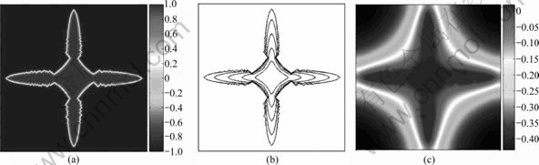
Fig.2 Dendritic growth shape of silicon without noise: (a) Phase field; (b) Interface evolution of phase field; (c) Thermal field
Table 1 Physical properties of silicon
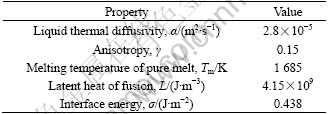
It is important to study the effect of secondary dendrite on material properties. In order to obtain facet dendrite with secondary dendrite, random noise is added to phase field equation during the simulation.
Dendrite shape with noise at t=25 000 ?t is shown in Fig.3. By comparing Fig.3 with Fig.2, facet dendrite shape with noise is similar to that without noise, but noise promotes the growth of side dendrite branches.
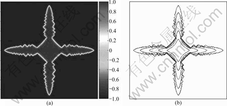
Fig.3 Dendritic growth shape of silicon with noise: (a) Phase field; (b) Interface evolution of phase field
4.2 Effect of anisotropy parameter
Anisotropy should be the physical value of material, but anisotropy in the range of 0.07-0.35 was studied to obtain some law in phase field simulation. The interface shapes of dendrite growth for various γ at Δ=-0.25, t= 20 000 ?t are given in Fig.4. It is noticed that crystal grows to facet and forms arc between two arms when γ is 0.07. When increasing the anisotropy value to 0.13, sizes of facet are very close, and the only noticeable discrepancy between arms turn into cusps. With further increasing the anisotropy value, facet grows smaller and the part of cusp becomes plane. The steady state tip velocity as the function of anisotropy is summarized in Fig.5. When γ≤0.13, the steady state velocity is a fixed value. With increasing the anisotropy value, the steady state velocity decreases gradually when γ≤0.25, and the decreasing of the steady state velocity becomes slow. The reason is that the range of missing orientation and the limit of initial crystal radius are increased[14], and the relation between the steady state velocity and anisotropy value meets with the following equation:
VSteadyd0/α=-15.136 5 γ5+15.267 2 γ4-5.605 94 γ3+
0.907 263 γ2-0.066 024 4 γ+0.006 960 47 (12)
Fig.4 Interface shape of dendritic growth at Δ=-0.25, t=20 000 ?t: (a) γ=0.07; (b) γ= 0.11; (c) γ=0.13; (d) γ=0.25; (e) γ=0.35

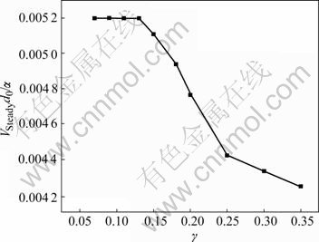
Fig.5 Steady state tip velocity vs anisotropy
4.3 Effect of undercooling
Fig.6 show the evolution of phase field for various undercooling at every 2500 time steps, t=10 000 Δt. It is seen that crystal grows from facet to facet dendrite, and dendrite shape becomes large gradually with time prolonging. A further analysis can be shown in Fig.7. When Δ=-0.05, dendrite tip velocity tends to zero. With increasing undercooling, dendrite tip velocity increases.

Fig.6 Evolution of phase field for various undercooling at t= 10 000 ?t: (a) Δ=-0.05; (b) Δ=-0.25; (c) Δ=-0.45; (d) Δ=-0.55
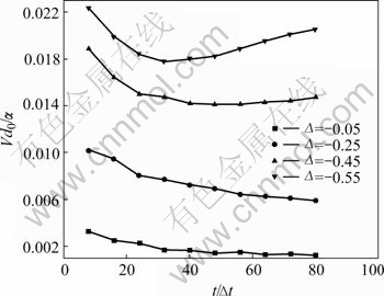
Fig.7 Relation of dendritic tip velocity vs time at various undercooling
4.4 Effect of coupling parameter
Coupling parameter is an important parameter between phase field and thermal field, which is known to play an important role in dendrite growth interface.
Fig.8 shows the isotherms around dendrite phase field shape at various coupling parameters, t=18 000 Δt. It is noticed that crystal grows from facet to facet dendrite; isotherms around dendrite change from circle to concave and size of corresponding faceted part decreases gradually with increasing coupling parameter, as shown in Figs.8(a) and (f), which agrees with Wulff theory.

Fig.8 Isotherms around dendritic phase field shape at various coupling parameter (t=18 000 Δt): (a) λ=1.596; (b) λ=3.192; (c) λ=4.787; (d) λ=6.383; (e) λ=7.979; (f) λ=9.575
The dendrite tip velocities at various coupling parameters are shown in Fig.9. Dendrite tip velocity falls to a steady state value after an initial fast growth. With increasing coupling parameter, dendrite tip velocity increases monotonically. When λ≥7.979, dendrite tip velocity occurs an increased trend and the interface becomes unstable.

Fig.9 Calculated dendritic tip velocity at various coupling parameter
5 Conclusions
1) The entire facet dendrite shape of silicon is successfully obtained by a new regularization phase field model, and noise can promote side branch growth of dendrite.
2) When γ≤0.13, the steady state tip velocity of dendrite is a fixed value and shapes are very similar. With further increasing anisotropy, facet grows smaller and cusp becomes plane.
3) With increasing the undercooling and coupling parameter, crystal grows from facet to facet dendrite.
4) The size of the facet part decreases gradually with increasing coupling parameter, which is in agreement with Wulff theory.
References
[1] BECKERMANN C, DIEPERS H J, STEINBACH I, KARMA A, TONG X. Modeling melt convection in phase-field simulations of solidification [J]. Journal of Computational Physics, 1999, 154: 468-496.
[2] BOETTINGER W J, WARREN J A, BECKERMANN C, KARMA A. Phase-field simulation of solidification [J]. Annu Rev Mater Res, 2002, 32: 163-94.
[3] LAN C W, SHIH C J, LEE M H. Quantitative phase field simulation of deep cells in directional solidification of an alloy [J]. Acta Materialia, 2005, 53: 2285-2294.
[4] UEHARA T, SEKERKA R F. Phase field simulations of faceted growth for strong anisotropy of kinetic coefficient [J]. Journal of Crystal Growth, 2003, 254: 251-261.
[5] KARMA A, RAPPEL W J. Phase-field method for computationally efficient modeling of solidification with arbitrary interface kinetics [J]. Physical Review E, 1996, 53(4): R3017-R3020.
[6] TAN L J, ZABARAS N. A level set simulation of dendrite solidification with combined features of front-tracking and fixed-domain methods [J]. Journal of Computational Physics, 2006, 211: 36-63.
[7] KARMA A, RAPPEL W J. Quantitative phase-field modeling of dendrite growth in two and three dimensions [J]. Physical Review E, 1998, 57(4): 4323-4349.
[8] ZHAO P, HEINRICH J C, POIRIER D R. Dendrite solidification of binary alloys with free and forced convection [J]. Int J Numer Meth Fluids, 2005, 49: 233-266.
[9] LAN C W. Recent progress of crystal growth modeling and growth control [J]. Chemical Engineering Science, 2004, 59: 1437-1457.
[10] EGGLESTON J J, MCFADDEN G B, VOORHEES P W. A phase-field model for highly anisotropic interfacial energy [J]. Physica D, 2001, 150: 91-103.
[11] KASAJIMA H, NAGANO E, SUZUKI T, KIM S G, KIM W T. Phase-field modeling for facet dendrite growth of silicon [J]. Science and Technology of Advanced Materials, 2003, 4: 553-557.
[12] LI J J, WANG J C, YANG G C. The effect of interface energy anisotropy on dendrite growth by phase field method [J]. Progress in Natural Science, 2005, 15(11): 1312-1317. (in Chinese)
[13] SUZUKI T, KIM S G, KIM W T. Two-dimensional facet crystal growth of silicon from undercooled melt of Si-Ni alloy [J]. Materials Science and Engineering A, 2007, 449: 99-104.
[14] KIM S G, KIM W T. Phase field modeling of dendrite growth with high anisotropy [J]. Journal of Crystal Growth, 2005, 275: e355-e360.
[15] VOORHEES P W, CORIELL S R, MCFADDEN G B. The effect of anisotropic crystal-melt surface tension on grain boundary groove morphology [J]. Journal of Crystal Growth, 1984, 67: 425-440.
[16] ZHANG G W, HOU H, CHENG J. phase field model for strong anisotropy of kinetic and highly anisotropic interfacial energy [J]. Trans Nonferrous Met Soc China, 2006, 16(s): s307-s313.
[17] TAKAKIA T, HASEBEB T, TOMITA Y. Two-dimensional phase-field simulation of self-assembled quantum dot formation [J]. Journal of Crystal Growth, 2006, 287: 495-499.
[18] LAN C W, SHIH C J. Phase field simulation of non-isothermal free dendrite growth of a binary alloy in a forced flow [J]. Journal of Crystal Growth, 2004, 264: 472-482.
[19] XU C L, WANG H Y, LIU C, JIANG Q C. Growth of octahedral primary silicon in cast hypereutectic Al-Si alloys [J]. J Cryst Growth, 2006, 291: 540-547.
Foundation item: Projects(50331040; 60171034) supported by the National Natural Science Foundation of China
Corresponding author: CHEN Zhi; Tel: +86-29-88493979; E-mail: c2002z@nwpu.edu.cn
(Edited by YANG Bing)

