
Interface structure and mechanical property of
aluminum cooler vacuum brazing joint
FENG Tao(冯 涛)1, LOU Song-nian(楼松年)1, WU Lu-hai(吴鲁海)1, LI Ya-jiang(李亚江)2
1. School of Materials Science and Engineering, Shanghai Jiao Tong University, Shanghai 200030, China;
2. School of Materials Science and Engineering, Shandong University, Ji’nan 250061, China
Received 28 July 2006; accepted 15 September 2006
Abstract: A kind of aluminum cooler was manufactured by means of vacuum brazing technique, and the cooler was examined by hydraulic pressure test. The result indicates that the test pressure of the cooler can reach 15 MPa. The fracture of the brazing joint belongs to the mixture type. There are secondary cracks, dimples, cleavage plane and grain-boundary features on the failure surface. The cracking process of aluminum cooler is as follows. The cracks are initiated on the interface, then expand under sub-critical state. When the stress on the remained zone reaches the maximum notch tensile strength of the brazing joint or the crack length reaches the critical value that the brazing joint fracture toughness property permits, the cooler will break sharply.
Key words: aluminum cooler; vacuum brazing; hydraulic pressure test; fracture
1 Introduction
Aluminum plate-wing style cooler is used for the cooling of machine oil in car engine. It is one of the key components for prolonging engine life and emitting engine power [1-2]. High temperature and high pressure liquid flows in the cooler and it is cooled by other liquid or fans outside. The original cooler is manufactured by mechanical machining, and then it is manufactured by salt bath dip brazing. With the development of vacuum technique, vacuum brazing becomes the best method to produce the aluminum cooler [3-4]. In this experiment the aluminum cooler is brazed by vacuum brazing equipment, and then the mechanical performances of the coolers are tested. The most important thing was safe, so the hydraulic pressure test is needed.
2 Experimental
LT-3 aluminum alloy plate used in this experiment was a kind of three-layer compounded material specially used for vacuum brazing. The core metal of LT-3 aluminum alloy was 3003 alloy and the cortex metal was 4004 alloy. The cladding rate was 10%-13%. The cortex metal was used as the filler metal during vacuum brazing.
The vacuum brazing parameters are shown in Fig.1. The manufacturing flow of aluminum plate- wing style cooler is: forging the plate and wing, cleaning the surface, assembling, vacuum brazing and hydraulic pressure test.
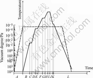
Fig.1 Aluminum cooler vacuum brazing technology A―Pre-vacuum time; B, D, F, H―Heating time; C, E, G, I, K―Keeping time; J―Controlled cooling time; L―Free cooling time
3 Result and analysis
3.1 Brazing joint microstructure
In the brazing joint, there is net-like eutectic structure and Si segregates at the grain boundary (seen in Fig.2). The direction of the massive Si is similar. Except Si and Al, the other intermetallic compounds in the brazing joint are analyzed by the X-ray diffractometry. The X-ray diffraction pattern of the brazing joint is shown in Fig.3.
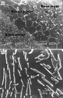
Fig. 2 Microstructures of brazing joint: (a) Brazing joint; (b) Si in brazing joint
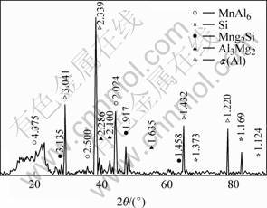
Fig.3 XRD pattern of brazing joint
3.2 Hydraulic pressure test
Every work piece gotten in the experiment was examined by hydraulic pressure test, and the results are listed in Table 1.
Table 1 Hydraulic pressure test data of work pieces

The effects of technique parameters on the hydraulic pressure test value are shown in Fig.4. The pressure becomes higher with the increase of brazing temperature. Then the pressure reaches the maximum value and decreases with the increasing of temperature (Fig.4(a)). The results indicate that the joint strength decreases if the brazing temperature is too high or too low. The effect of keeping time is similar as that of the brazing temperature (Fig.4(b)). The suitable brazing parameters of aluminum cooler are: brazing temperature 628 ℃, keeping time 10 min.

Fig.4 Relationship between brazing parameters and hydraulic pressure: (a) Brazing temperature; (b) Keeping time
3.3 Fractography analysis
It is noticed that for all brazing conditions the failure is located at the brazing joint. The fractographs of samples No.4 and No.6 were analyzed by SEM. The fracture microstructure of sample No.6 is shown in Fig.5. Fig.5(b) is the amplifying microstructure of zone Ⅰ. There are dimples on the surface (marked with A). In the hydraulic pressure test, the micro dimple in zone A partially grows, and the growing direction is vertical to some of the cleavage planes.
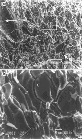
Fig. 5 Fractographs of sample No.6 brazing joint: (a) Fractograph of brazing joint; (b) Local structure of zone Ⅰ
The step-shape cleavage plane can be seen in zone E and zone Ⅰ(Fig.5(a)). The orientation of these cleavage planes changes with the difference of the grain orientation. The orientation difference between grains causes the cracks to branch along with different planes. The orientation of grain B and grain C is different, so the cleavage step, which is originated from grain B, causes grain boundary crack around grain C (Fig.5(b)). And the micro cracks of the both grains affect each other.
The second cracks are full of the whole surface, and the two cracks (marked with D) are most obvious (Fig.5(a)). The crack D expands through dimple A. The crack expanding direction is generally same as the dimple developing direction. The big second crack affects the orientation of the other small second cracks around it, and these small second cracks either originate from it or combine with it.
Increasing the brazing temperature to 635 ℃, the joint strength decreases greatly. The fractograph of sample No.4 was also analyzed, which is shown in Fig.6.
The fracture surface is composed of cleavage planes (Fig.6). There is a very short second crack or no second cracks (marked with E). Fig.6(b) is the local structure of zone Ⅱ of Fig.6(a). There are tearing edges on the surface (marked with F). The direction of these tearing edges is consistent, parallel to each other and the distance between two tearing ridges is about 7 ?m, which accords with the crystallographic direction of aluminum alloy. There are cragged brow-shape micro cracks vertical to the tearing ridges (marked with G). These micro cracks are very short.

Fig. 6 Fractographs of sample No.4 brazing joint: (a) Fractograph of brazing joint; (b) Local structure of zone Ⅱ
3.4 Fracture mechanism
The stress condition of the work piece is an important cracking reason. When the aluminum cooler is in the hydraulic pressure test, the joint of the cooler is under three-direction stress condition. The cracking process of aluminum cooler is as follows. The cracks are initiated on the interface, then they expand under sub-critical state. When the stress on the remained zone reaches the maximum notch tensile strength of the brazing joint or the crack length reaches the critical value that the brazing joint fracture toughness property permits, the cooler will break sharply. In this cracking mode, on the fracture interface, there are cleavage planes, dimples and secondary cracks [5-6].
The fracture of aluminum cooler belongs to the mixture fracture. The remained oxidation film and the brittle intermetallic compounds might cause the micro cracks under the stress. Si segregates on the grain boundary and the orientation of it is similar, and there is little α(Al) between two Si phases. The cracking process caused by the segregated Si is as follows. Firstly the crack initiation forms on the Al/Si interface, then the cracks expand along the surface of Si crystal or go through the α(Al) base metal or Si crystal, the cracks are connected near Si phase, at last the work piece breaks off.
4 Conclusions
1) The hydraulic pressure test indicates that the pressure increases with the brazing temperature increasing and the keeping time prolonging. The suitable parameters are: brazing temperature 628 ℃, keeping time 10 min. The pressure of hydraulic pressure test could reach 15 MPa.
2) The fracture analysis indicates that the cracking of aluminum cooler is a kind of mixture fracture. On the surface of the fracture, there are second cracks, dimples, cleavage planes and other fracture characteristics. The cracking process of aluminum cooler is as follows. The cracks are initiated on the interface, then they expand under sub-critical state. When the stress on the remained zone reaches the maximum notch tensile strength of the brazing joint or the crack length reaches the critical value that the brazing joint fracture toughness property permits, the cooler will break sharply.
References
[1] TERRILL J R, COCHRAN C N, STOKES J J, HAUPIN W E. Welding Journal, 50(12): 833s-839s.
[2] HOKE W II, AMENHEUSER C. Techniques for aluminum brazing in vacuum furnaces[J]. Welding Journal, 1993, 10(72): 65-67.
[3] ANDENSON W A. Metallurgical studies of the vacuum brazing of aluminum[J]. Welding Journal, 1977, 56(10): 314s-318s.
[4] IUAHASHI Y, NOMOTO Z M, LANGDON T G. Metallurgical and Materials Transactions A, 1997, 28(5): 1437-1447.
[5] VRRETA S E, LOUCHET F, GHILARDUCEI A. Mater Sci and Eng A, 2001, 302(6): 300-307.
[6] WANG Yuan-liang, QU Jin-shan, YAN Chuan-peng. The Chinese Journal of Nonferrous Metals, 1997, 7(1): 69-74.
(Edited by YANG Bing)
Corresponding author: FENG Tao; Tel: +86-21-62932427; E-mail: ft_210750@sina.com.cn

