
J. Cent. South Univ. (2021) 28: 168-178
DOI: https://doi.org/10.1007/s11771-021-4594-0

Dynamic modelling of 2-DOF luffing mechanism with serial closed kinematic chains
ZHU Zhen-xin(朱振新)1, ZHU Jian-xin(朱建新)1, KANG Hui-mei(康辉梅)2, QIAN Huan-yun(钱奂云)3
1. State Key Laboratory of High Performance Complex Manufacturing, Central South University,Changsha 410083, China;
2. College of Engineering and Design, Hunan Normal University, Changsha 410081, China;
3. The National Enterprise R&D Center, Sunward Intelligent Equipment Co. Ltd., Changsha 410100, China
 Central South University Press and Springer-Verlag GmbH Germany, part of Springer Nature 2021
Abstract: Luffing mechanism is a key component of the construction machinery. This paper proposes a two degree of freedom (2-DOF) luffing mechanism, which has one more pair of driving cylinders than the single DOF luffing mechanism, to improve the performance of the machinery. To establish the dynamic model of the 2-DOF luffing mechanism, firstly, we develop a hierarchical method to deduce the Jacobian matrix and Hessian matrix for obtaining the kinematics equations. Subsequently, we divide the luffing mechanism into six bodies considering actuators, and deduce the kinetic equations of each body by the Newton-Euler method. Based on the dynamic model, we simulate the luffing process. Finally, a prototype is built on a pile driver to validate the model. Simulations and experiments show that the dynamic model can reflect the dynamic properties of the proposed luffing mechanism. And the control strategy that the front cylinders retract first shows better mechanical behavior than the other two control strategies. This research provides a reference for the design and application of 2-DOF luffing mechanism on construction machinery. The modeling approach can also be applied to similar mechanism with serial closed kinematic chains, which allows to calculate the dynamic parameters easily and exactly.
Key words: luffing mechanism; dynamic model; hierarchical method; control strategy; prototype
Cite this article as: ZHU Zhen-xin, ZHU Jian-xin, KANG Hui-mei, QIAN Huan-yun. Dynamic modelling of 2-DOF luffing mechanism with serial closed kinematic chains [J]. Journal of Central South University, 2021, 28(1): 168-178. DOI: https://doi.org/10.1007/s11771-021-4594-0.
1 Introduction
Luffing mechanism is widely used in construction machinery such as piling machinery, hoisting machinery and rock drilling machinery. It erects mast during luffing, adjusts verticality during locating, and transmits load during drilling. Many efforts have been made to analyze the luffing mechanism. JIN et al [1] established the kinematics model of the luffing mechanism and analyzed the luffing mechanism based on the complex vector analysis. On the basis of the random optimal algorithm and the genetic and annealing algorithm, LIN et al [2] proposed a compound genetic annealing algorithm to optimize the luffing mechanism locus of a plane link. KANG et al [3, 6], ZHU et al [4, 5] and ZHAO et al [7] established the dynamic model of the luffing mechanism of rotary drilling rigs, and studied the driving force and constraining force during lifting or luffing. SUN et al [8] and WANG et al [9] studied the influence of driving speed, acceleration and force on the dynamic characteristics of the luffing mechanism in a crane duringluffing. According to the multi-body dynamics and bond graph theory, JIANG et al [10] and HU et al [11] established the bond graph model of the mechanical-hydraulic coupling dynamics of the luffing mechanism, and studied the relationship between hinge position and dynamic parameters. ZHU et al [12] analyzed the finite element and optimized the luffing mechanism structure. FAN et al [13], ZHANG [14], HU et al [15] and CABRERA et al [16] optimized the structural parameters of the luffing mechanism based on kinetic analysis and kinematical analysis. XU et al [17] proposed an optimization design for the luffing mechanism based on the hybrid neural network, which can be used to determine the initial parameters of the optimization design. The initial parameters usually have the general characteristics of a certain kind of luffing mechanism. ZHAO et al [18] proposed an optimization design method based on the genetic algorithm and finite element analysis, which minimizes the weight, the unbalanced moment and the vertical drop of the cargo during luffing, while keeps the technical parameters of portal crane.
These researches all focused on the single DOF four-bar luffing mechanism (Figure 1), which is a common luffing mechanism with a simple structure. The luffing mechanism is driven by a single-stage cylinder, leading to a small luffing angle. Due to the limited size of the machinery platform, the hinge that connects the cylinder and the mast is located in the middle and the lower part of the mast for achieving a larger luffing angle, which results in poor support.
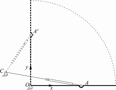
Figure 1 Single DOF luffing mechanism
These researches paid more attention to the kinematics analysis [1, 2], dynamics research [3-10], structural strength analysis [11, 12], structure parameter optimization [13-16] and mechanism optimization methods [17, 18]. Very few studies considered the overall modelling, analysis and testing of luffing mechanism, especially the complex luffing mechanism.
The Lagrange method [3, 5, 6, 10, 19] and Newton-Euler method [8, 9, 20] have been widely used for dynamic modeling. The Lagrange method has a neat equation, which eases the design of controllers of the whole mechanism, but it only concerns the driving force. The Newton-Euler method has low computation efficiency, because it considers the internal reaction forces between bodies. The luffing mechanism is the key component to transmit the load of the construction machinery, so deriving an effective and detailed dynamic model to characterize the relations between different bodies is important for the dynamic analysis and the design of serial counterparts. Therefore, the Newton-Euler approach is used in this research.
This study proposes a 2-DOF luffing mechanism with serial closed kinematic chains [21], which has better luffing capacity and supporting performance than the traditional single DOF luffing mechanism.We establish a complete dynamic model for the 2-DOF luffing mechanism considering the mass and inertia of the actuator. Then we analyze its dynamic characteristics during luffing, and verify the model by experiments.
2 Mechanism description
As shown in Figure 1, the preconditions of the single DOF luffing mechanism are as follows:
Condition 1: The stroke of the cylinder should ensure the mast to move from being horizontal to being vertical, that is
 (1)
(1)
where l is ||AO||; L is the maximum stroke of the cylinder; xc and yc are the coordinates of point C.
Condition 2: The driving angle of the cylinder should ensure the erecting force at the initial stage of luffing, that is
 (2)
(2)
where α is the driving angle of the cylinder.
We take a big pile driver as an example. Assume that the mast height is 30 m. According to the engineering application requirements, lmin=16 m, Lmax=4.5 m, αmin=10°. The feasible area of hinge C connecting the cylinder and platform of the pile driver is shown in Figure 2. The maximum yc is only 1.28 m, which can not meet the practical demand in mechanic engineering obviously.
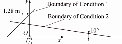
Figure 2 Feasible area of hinge
The proposed 2-DOF luffing mechanism consists of a mast, two front cylinders, two rear cylinders and a luffing frame (Figure 3). The front cylinders and rear cylinders are symmetrically assembled in accordance with the longitudinal plane. The two rear cylinders are parallel to the longitudinal plane, and there is a small angle between the front cylinder and longitudinal plane. The cylinder actuators move synchronouslyand they are controlled by the electro-hydraulic system.
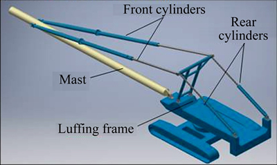
Figure 3 Structure of 2-DOF luffing mechanism
The luffing mechanism in big construction machinery takes heavy loads and moves slowly. The angle between the front cylinders and the longitudinal plane is small and changes subtly during luffing. To simplify the deduction of dynamic equations of the complex mechanism, we make the following assumptions.
Assumption 1: Simplify the spatial mechanism to the planar mechanism composed of two four-bar planar mechanisms (Figure 4).
Assumption 2: Eliminate the friction of the passive joints and rod flexibility, and assume all links to be rigid bodies.
In Figure 4, the closed-chain AEB is the guide-bar mechanism, and CDE is the rocker block mechanism. The degree of freedom, M, is calculated by:
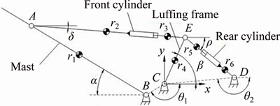
Figure 4 Schematic diagram of 2-DOF luffing mechanism
 (3)
(3)
where n=6 is the number of components including the mast, the luffing frame, 2 cylinder blocks and 2 cylinder rods; pl=8 is the number of revolute pairs, including 5 joints (A, B, C, D, E) and 2 sliding pairs, among which hinge E is a complex joint; ph=0 is the number of higher pairs.
The 2-DOF luffing mechanism erects the mast by the motion of two cylinder pairs, so it has better luffing capacity and supporting performance than the traditional single DOF luffing mechanism. Luffing motion affects the stability and safety of construction machinery directly. Different luffing mechanism leads to different dynamic performance, so it is necessary to further analyze the 2-DOF luffing mechanism to get information for the design of serial counterparts.
3 Kinematics equations
3.1 Forward position problem
For Figure 4, we assume 


 Let d1 and d2 be the input variables; α and β be the output variables; hinge C be the origin of the Cartesian coordinates.
α and β can be derived from inputs (d1 and d2) by forward kinematics equations. The coordinates of hinge A, E and D can be expressed as:
 (4)
(4)
 (5)
(5)
 (6)
(6)
And α and β can be easily obtained by Eqs. (4)-(6) and cosine theorem:
 (7)
(7)
 (8)
(8)
where


 .
.
3.2 Inverse position problem
The inverse kinematics equations are used to calculate inputs d1 and d2 in terms of α and β, as follows:

 (9)
(9)
 (10)
(10)
3.3 Jacobin matrix problem
The first-order Jacobin velocity matrix describes the relationship between the output and the input velocity vectors as follows:
 (11)
(11)
where J is the Jacobin matrix; is the input velocity vector; and
 is the output velocity vector. As shown in Figure 4, when the position of hinges and the length of rods are fixed, output β is determined only by input d2, and output α is determined by input d1 and d2. Thus, it is difficult to directly solve the first-order velocity Jacobin matrix. In this paper, a hierarchical method is proposed to simplify the solution of Jacobin matrix as follows.
We assume the recursive relationship between the series passive part vectors q1, q2, …, qn as follows:

 (12)
(12)
we have
 (13)
(13)
According to the hierarchical method, the Jacobin matrix of the 2-DOF luffing mechanism is detailed in the following.
Differentiating Eq. (9) leads to:
 (14)
(14)
where


In order to clarify the relationship between and
and 
 we should find the relationship between
  and
and
Differentiating Eq. (10) leads to:
 (15)
(15)
where


Substituting Eq. (15) to Eq. (14), we get:
 (16)
(16)
where


 And J is a 4×4 Jacobin matrix.
3.4 Hessian matrix problem
Similarly, the hierarchical method can be used to calculate the second-order acceleration Hessian matrix, which describes the mapping relationship between the output and the input acceleration vectors.
Differentiating Eq. (13), we get:
 (17)
(17)
where is the input acceleration vector;
  is the output acceleration vector; * is the operation rules of scalar product.
Differentiating Eq. (14), we have:
 *
* (18)
(18)
where


 ;
;
 ;
;

 .
.
Differentiating Eq. (15), we get:

 (19)
(19)
where

Substituting Eq. (19) to Eq. (18), we have:
 *
* (20)
(20)
where


 ;
;


 .
.
 is a 2×2×2 Hessian matrix.
3.5 Kinematics of each body
In Figure 4, δ and ρ are used to solve the kinematics of each body, which can be calculated as follows:
 ,
,
 (21)
(21)
Define ωi as the angular velocity, and let ωi be the angular acceleration. Differentiating Eqs. (7), (8), (21) separately, we get:


 ,
,
 ,
, (22)
(22)
The centroid acceleration of the rigid body 1 can be deduced from Eq. (4):
 ,
,
 (23)
(23)
where r1 is the distance between the centroid of rigid body 1 and hinge B.
Similarly, the centroid acceleration equations of rigid body 2, 3, 4, 5, 6 are obtained:

 (24)
(24)

 (25)
(25)

 ,
,
 (26)
(26)
 (27)
(27)
 ,
,
 ,
,
 (28)
(28)
where r2 is the distance from the centroid of rigid body 2 to hinge A; r3 is that from rigid body 3 to hinge E; r4 is that from rigid body 4 to hinge C; r5 is that from rigid body 5 to hinge E; r6 is that from rigid body 6 to hinge D.
Equations (4)-(28) constitutes the kinematics equations of the 2-DOF luffing mechanism.
4 Newton-Euler equations
According to the D’Alembert principle, the driving force, the constraining force and the inertia force on the particle system form a balanced force system [22, 23]. The complete expression of the 2-DOF luffing mechanism can be obtained using the Newton-Euler method, which incorporates the constraining force and driving force. The Newton- Euler equations can be demonstrated by the force balance equations of the center of the rigid body. To establish a complete dynamic model for the whole mechanism, we consider the mass and inertia of the cylinder, rather than simplify the cylinder as an input force. We divide the whole system into six rigid bodies, which are the mast, front cylinder block, front cylinder piston, luffing frame, rear cylinder piston and rear cylinder block. These bodies are referred to as rigid body 1 to body 6 in sequence. The force analysis of these rigid bodies are shown in Figure 5, in which the friction of the passive joints and other disturbances are ignored. The force of cylinder actuator is split into the torque, the axialforce and the radialforce.
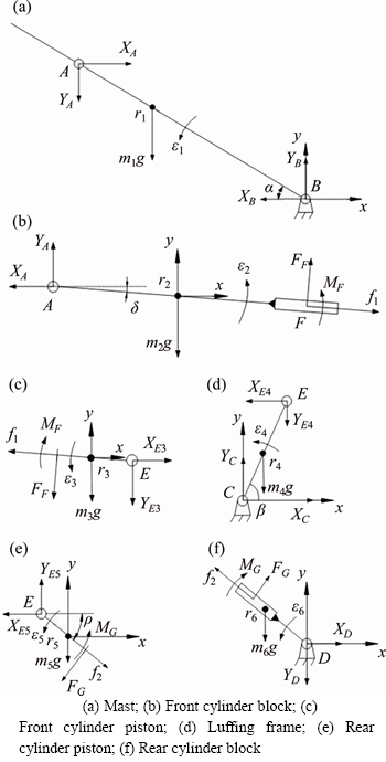
Figure 5 Mechanical analysis diagram of the six rigid bodies of cylinder:
Rigid body 1 rotates around hinge B (Figure 5(a)). According to the D’Alembert principle, the force balance equations can be written as:
 (29)
(29)
where I1B is the moments of the inertia of rigid body 1 around hinge B; and g is the acceleration of gravity.
Rigid body 2 starts compound motion (Figure 5(b)), and the force balance equations can be written as:
 (30)
(30)
where I2 is the moments of the inertia of rigid body 2 around its centroid; l3 is the length of the front hydraulic cylinder rod.
Rigid body 3 starts compound motion (Figure 5(c)), and the force balance equations can be expressed as:
 (31)
(31)
where I3 stands for the moments of the inertia of rigid body 3 around its centroid.
Rigid body 4 rotates around hinge C (Figure 5(d)), and its force balance equations can be expressed as:
 (32)
(32)
where I4C denotes the moments of the inertia of rigid body 4 around hinge C.
Rigid body 5 starts compound motion (Figure 5(e)), and its force balance equations can be written as:
 (33)
(33)
where I5 is the moments of the inertia of rigid body 5 around its centroid; l4 is the length of the rear cylinder rod.
Rigid body 6 rotates around hinge C (Figure 5(f)), and its force balance equations can be written as:
 (34)
(34)
where I6 is the moments of the inertia of rigid body 1 around hinge B.
Moreover, the force balance equation at point E is:
 (35)
(35)
Equations (23)-(29) describe the relation between driving force, constraining force and centroid acceleration of each rigid body. They form the Newton-Euler equations of the 2-DOF luffing mechanism.
Given that the 2-DOF luffing mechanism has been simplified to the planar mechanism in Section 2, the driving force of the single rear cylinder is half of the above calculated value, and
that of the single front cylinder is times of the above calculated value.
5 Simulation and analysis
5.1 Parameter definition
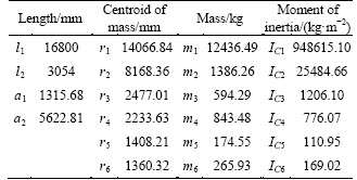
Producing the physical prototype of the luffing mechanism costs a lot, so it is necessary to analyze the driving force and constraining force to improve the design of the structure and controller. The empirical structure parameters are listed in Table 1. The experimental motion equations of actuators are as follows:
 (36)
(36)
 (37)
(37)
where d01 and d02 are the initial length of the front cylinder and rear cylinder, respectively; v1= 0.0468 m/s and v2=0.0426 m/s are the stable speeds of the front and cylinders, respectively, when they are doing the uniform motion.
Table 1 Main parameters of 2-DOF luffing mechanism
5.2 Driving force analysis
The two cylinder pairs determine the mast posture. Simulating the driving force within the mast posture range is useful for designing of the actuating system. The relationship between the driving force and the cylinder displacement is shown in Figure 6, in which the curves have been smoothed by neglecting the impact load.
As Figure 6 shows, the load of the front cylinder, F1, is non-linearly positively correlated with d1 and d2. When the front and rear cylinder is fully retracted, F1 has the minimum value. The value of F1 is always positive under any mast posture.
The load of the rear cylinder, F2, is non-linearly correlated with d1 and d2. When the rear cylinder is completely retracted and the front one is completely extended, F2 has the maximum value. When the front and rear cylinder are fully retracted, F2 has the minimum value. When d1<15945 mm and d2<2983 mm, F2 is negative.
5.3 Constraining force analysis
Analyzing the constraining force of hinges,particularly, the hinge connecting the luffing mechanism to the machinery, is important to the designing of the platform and the stability of machinery during luffing. The 2-DOF luffing mechanism has three control strategies considering the maneuverability during luffing. 1) Strategy 1: the rear cylinder is completely retracted before the front one. 2) Strategy 2: the front cylinder is completely retracted before the back one. 3) Strategy 3: the rear and the front cylinder are retracted simultaneously.
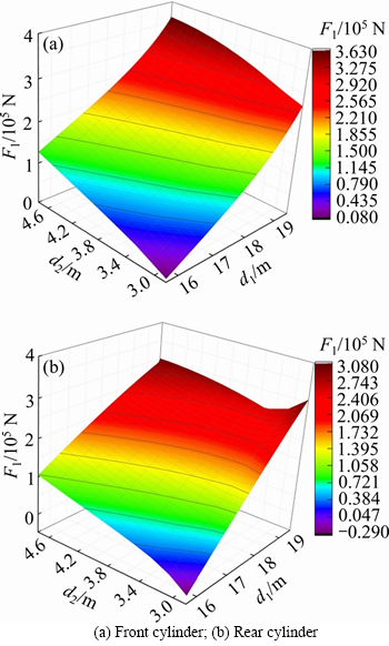
Figure 6 Driving force within mast posture range of:
The constraining force (amplitude) of these three strategies is shown in Figure 7. The constraining force of hinge A is equal to F1, and that of hinge D is equal to F2. The impact load appears, when αis 0°, 35°, 58°, 71°, 90°, which corresponds to the model of the hydraulic actuator system. As shown in Figure 7, the constraining force of hinge D, B, A, C is 301611 N, 360651 N, 363840 N and -239397 N, respectively, at the initial stage of luffing. When α>86°, the constraining force of hinges D and C becomes negative, because the gravity center of the mast and luffing frame has changed. At the end stage of luffing, the constraining force of hinge D, B, A, C is -30122 N, 75562 N, 7540 N and -32671 N, respectively.
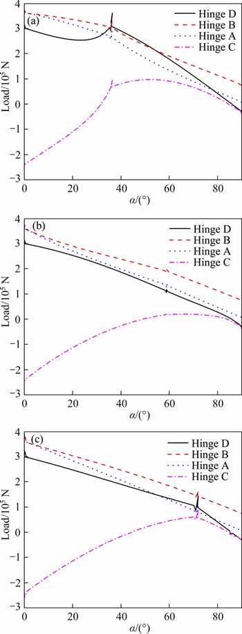
Figure 7 Constraining force of cylinders in strategy 1 (a), strategy 2 (b) and strategy 3 (c)
Strategy 1: As shown in Figure 7(a), when α=35°, the rear cylinder is completely retracted, and when α=90°, the front one is completely retracted. The constraining force of hinge C is a negative value until the luffing mechanism pass theposition
where the rear cylinder is collinear with the front cylinder, that is, when α=32°. When the rear cylinder starts retracting, the maximum instantaneous constraining force of hinge D is 311342 N, corresponding to the maximum driving force of the rear cylinder. When the front cylinder starts retracting, the maximum instantaneous constraining force of hinge A is 297202 N, corresponding to the maximum driving force of the front cylinder. The maximum positive constraining force of hinge C is 97422 N, when α=52°. In such case, the constraining force of hinge D reaches the maximum of 369261 N, exceeding the initial load and the rated load of the cylinder, which should be avoided.
Strategy 2: As shown in Figure 7(b), when α=58°, the front cylinder is completely retracted. And when α=90°, the rear one is completely retracted. The value of the constraining force of hinge C is positive when α=49°, where the rear cylinder is collinear with the front cylinder. When the front cylinder starts retracting, the maximum instantaneous constraining force of hinge A is 375353 N, corresponding to the maximum driving force of the front cylinder. When the rear cylinder starts retracting, the maximum instantaneous constraining force of hinge D is 119911 N, corresponding to the maximum driving force of the rear cylinder. The maximum positive load of hinge C is 22298 N, when α=66°.
Strategy 3: As shown in Figure 7(c), from Eqs. (36) and (37), the luffing time in strategy 3 is only 82 s, shorter than that in strategy 1 and strategy 2 (133 s). When α=71°, the rear cylinder is completely retracted. The constraining force of hinge C is a negative value until the luffing mechanism passes the position where the rear cylinder is collinear with the front cylinder, that is, when α=4°. The maximum positive load at hinge C is 94195 N, when α=72°. In the engineering practice, considering the maneuverability and safety of the large-size pile driver during luffing, the strategy that the front and rear cylinder retract simultaneously should be avoided.
Generally, in strategy 2 and strategy 3, the driving force and the constraining force change more gently than strategy 1. In strategy 2, the compressiverod of the luffing frame is more stable than strategy 1 and strategy 3.
6 Model validation
A prototype of the proposed 2-DOF luffing mechanism based on a hydraulic crawler pile driver has been built to verify the model (Figure 8). The mast height is 33 m and the engine power is 164 kW.
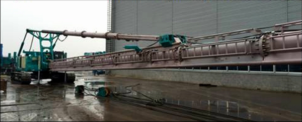
Figure 8 Testing platform based on hydraulic crawler pile driver
In order to validate the dynamic model, we tested the prototype using different control strategies. The output pressure of the cylinders was measured by pressure sensors assembled on their oil ports. The angle of mast was measured by the angle sensor. The cylinders were powered by the loading- sensing hydraulic system, whose flow is only determined by the opening size of proportional reversing valve and is not influenced by the load change. The rated pressure and the rated flow are 30 MPa and 90 L/min, respectively. As shown in Figure 9, the testing curve has a variation tendency similar to that of the simulation curve, so the model is reliable. But the testing curve has a larger fluctuation due to the peculiarity of the hydraulic system.
7 Conclusions
In this paper, a 2-DOF luffing mechanism with serial closed kinematic chains has been proposed. It has two front cylinders and two rear cylinders. We established the dynamic model of the 2-DOF luffing mechanism by a hierarchical method. The mechanism was divided into six rigid bodies considering the mass and inertia of the actuator, and the differential equations of motion and the force balance equations of all bodies were derived by the Newton-Euler method. Finally, the dynamic model was validated by a prototype on a hydraulic crawler pile driver. The following conclusions can be drawn:
1) The luffing strategy that the front cylinders retract first shows better mechanical behavior than the other two strategies.
2) The research laid a solid theoretical and technical foundation for the design and application of the 2-DOF luffing mechanism in construction machinery.
3) The modelling approach can shed some light on the researches of the mechanism with serial closed kinematic chains, and allows an easy and exact calculation of dynamic parameters.
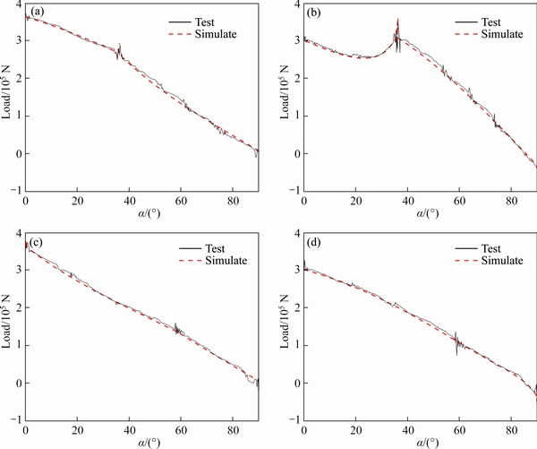
Figure 9 (a) Front hydraulic load of luffing strategy 1; (b) Rear hydraulic load of luffing strategy 1; (c) Front hydraulic load of luffing strategy 2; (d) Front hydraulic load of luffing strategy 2
Contributors
The overarching research goals were developed by ZHU Zhen-xin and ZHU Jian-xin. ZHU Zhen-xin, ZHU Jian-xin and QIAN Huan-yun assembled the prototype, organized the test, and analyzed the measured data. ZHU Zhen-xin and KANG Hui-mei established the models, calculated the predicted force, and analyzed the calculated results. The initial draft of the manuscript was written by ZHU Zhen-xin, ZHU Jian-xin, and KANG Hui-mei. All authors replied to reviewers’ comments and revised the final version.
Conflict of interest
ZHU Zhen-xin, ZHU Jian-xin, KANG Hui-mei, and QIAN Huan-yun declare that they have no conflict of interest.
References
[1] JIN Yao, HE Xin, XIA Yi-min, KANG Hui-mei. Coupled modeling simulation and kinematics analysis of luffing mechanism for mobile crane [J]. Journal of Machine Design, 2017, 34(9): 12-17. DOI: 10.13841/j.cnki.jxsj.2017.09.003. (in Chinese)
[2] LIN Xiao-tong, LIN Xiao-hui, HUANG Wei, WANG Ning-sheng. Compound genetics annealing optimal algorithm for realization of locus deduction of a plane link [J]. Journal of Southeast University (English Edition), 2002, 18(4): 310-314.
[3] KANG Hui-mei, HE Qing-hua, ZHU Jian-xin. Dynamic modeling and simulation of mast link frame system of rotary drilling rig [J]. Journal of Central South University (Science and Technology), 2010, 41(2): 532-538. (in Chinese)
[4] ZHU Jian-xin, XIE Song-yue, HU Xiong-wei, LI Xiong. Simulation analysis of the lifting force of parallelogram cylinder of the parallelogram system of rotary drilling rig based on ADAMS [J]. Modern Manufacturing Engineering, 2009, 11: 119-123. DOI: 10.16731/JCNKI.1671-3133.2009. 11.020. (in Chinese)
[5] HE Qing-hua, KANG Hui-mei, ZHU Jian-xin, XU Yi-she. Dynamic mechanical properties of working device of rotary drilling rig under lift arm luffing conditions [J]. Journal of Central South University (Science and Technology), 2012, 43(6): 122-126. (in Chinese)
[6] KANG Hui-mei, HE Qing-hua, XIE Song-yue, ZHU Jian-xin. Mechanics analysis of rotary drilling rig under drilling bucket-lifting conditions [J]. Engineering Mechanics, 2010, 27(10): 214-218. (in Chinese)
[7] ZHAO Wei-min, JIANG Wen-ge, ZU Hai-ying, HU Chang- sheng. Impact of amplitude angle for rotary drilling machine [J].Construction Mechanization, 2008, 6: 36-38. (in Chinese)
[8] SUN Guang-fu, LIU Jie. Dynamic responses of hydraulic crane during luffing motion, mechanism and machine theory [J]. 2006, 41: 1273-1288. DOI: 10.1016/j.mechmachtheory. 2006.01.008.
[9] WANG Peng-ju, FANG Yong-chun, XIANG Ji-lei, ZHAO Zhen-jie. Dynamics analysis and modeling of ship mounted boom crane [J]. Journal of Mechanical Engineering, 2011, 47(20): 34-40. (in Chinese)
[10] JIANG Tao, YOU Yi-ping, YANG Hu, WANG AN-lin. Integrated model based analysis of mast mechanism of rotary drilling rig and its dynamic characteristics [J]. Journal of Tongji University, 2012, 40(5): 729-734. (in Chinese)
[11] HU Jun-ping, LI Ke-jun. Dynamics model of mechanical hydraulic coupling of auger driller during luffing motion by bond graph [J]. Journal of Central South University (Science and Technology), 2016, 47(2): 495-502. (in Chinese)
[12] ZHU Jin-guang, CHEN Min-ge, LIU An-ning, LENG Jun. Finite element analysis for the working equipment of drilling rigs [J]. Agricultural Equipment & Vehicle Engineering, 2007, 2: 24-27. (in Chinese)
[13] FAN Qing, ZENG Yang. Design of luffing system with genetic algorithm by considering weight of each optimized goal [J]. Chinese Journal of Construction Machinery, 2013, 11(4): 324-326. DOI: 10.15999/j.cnki.311926.2013.04.004. (in Chinese)
[14] ZHANG Yang. Analysis and optimization of luffing mechanism of ZMK5530TZJ100 carrier mounted rig [J]. Journal of Machine Design, 2019, 36(3): 67-72. DOI: 10.13841/j.cnki.jxsj.2019.03.012. (in Chinese)
[15] HU Jun-ping,PENG Yao-ming. Optimization of hinge point position of auger driller luffing mechanism based on PSO algorithm [J]. Chinese Journal of Engineering Design, 2018, 25(5): 561-566, 596. (in Chinese)
[16] CABRERA J A, SIMON A, PRADO M. Optimal synthesis of mechanisms with genetic algorithms [J]. Mech Mach Theory, 2002, 37: 1165-1177. DOI: 10.1016/s0094- 114x(02)00051-4.
[17] XU Xue-song, HU Ji-quan. Parameter optimization design based on hybrid neural network of gantry crane luffing mechanism [J]. Chinese Journal of Mechanical Engineering, 2005, 41(4): 220-224. (in Chinese)
[18] ZHAO Qiong, TONG Shui-guang, ZHONG Wei, GE Jun-xu. Optimal design of luffing mechanism of portal crane based on genetic algorithm and finite element analysis [J]. Journal of Zhejiang University (Engineering Science), 2015, 49(5): 880-886. (in Chinese)
[19] ABO-SHANAB R F. Dynamicmodeling of parallel manipulators based on Lagrange-D’Alembert formulation and Jacobian/Hessian matrices [J]. Multibody System Dynamics, 2019, 48(4): 403-426. DOI: 10.1007/s11044- 019-09705-0.
[20] HE Jun, ZHENG Hai-chao, GAO Feng. Dynamics and control of a 7-DOF hybridmanipulatorfor capturing a non-cooperative target in space [J]. Mechanism and Machine Theory, 2019, 140(10): 83-103. DOI: 10.1016/ j.mechmachtheory.2019.05.020.
[21] QIAN Huan-yun, CHEN Zi-lin, SHI Xiao-hui, LI Hai-jian. A pile driver and its installation and applying method: Korea, 10-1894388 [P]. 2018-08-28.
[22] WITTENBURG J. Dynamics of systems of rigid bodies [M]. Stuttgart: B.G. Teubner, 977: 82-124. DIO: 10.1007/ 978-3-322-90942-8. (in Chinese)
[23] KOSTIC D, DEJAGER B, STEINBUCH M, HENSEN R. Modeling and identification for high-performance robot control: An RRR-robotic arm case study [J]. IEEE Transactions onControlSystems Technology 2004, 12(6): 904-919. DOI: 10.1109/tcst.2004.833641.
(Edited by ZHENG Yu-tong)
中文导读
串联多闭链二自由度变幅机构的动力学建模
摘要:变幅机构是工程机械的关键部件。不同于单自由度变幅机构,本文设计了一种两组液压缸驱动的二自由度变幅机构以提高变幅性能。为了建立该机构的动力学模型,首先,提出层次化方法推导出雅可比矩阵和海森矩阵,继而得到运动学方程。然后,考虑驱动器将该机构拆分成6个刚体,并采用牛顿欧拉法求得动力学方程,基于动力学模型对变幅过程进行仿真分析。最后,在桩架平台上搭建样机模型。仿真和试验研究表明,动力学模型能准确地反映该变幅机构的动力学特性。前液压缸先收缩再后液压缸收缩的控制策略较另外两种控制策略具有更优的力学性能。本文可指导二自由度变幅机构在工程机械上的设计及应用。该建模方法可应用于类似串连多闭链结构,以准确快速地推导动力学模型。
关键词:变幅机构;动力学模型;层次化方法;控制策略;样机模型
Foundation item: Project(2015B020238014) supported by the Science and Technology Program of Guangdong Province, China
Received date: 2020-03-26; Accepted date: 2020-08-20
Corresponding author: ZHU Jian-xin, PhD, Professor; Tel: +86-13017315609; E-mail: zjianx-918@163.com; ORCID: https://orcid.org/ 000-0001-8922-8674

