
J. Cent. South Univ. (2019) 26: 2307-2317
DOI: https://doi.org/10.1007/s11771-019-4175-7

Forward hot extrusion forming process of 4-lobe aluminum alloy helical surface rotor
XIA Feng(�ķ�)1, LI Hui(���)1, LIU Hou-gen(�����)1, ZHAO Bei-bei(�Ա���)1,
ZHANG Zhao-qiang(����ǿ)2, LU Di-hua(½�ػ�)2, CHEN Jian-qiang(�½�ǿ)2
1. School of Mechanical and Electrical Engineering, Central South University, Changsha 410083, China;
2. Kingle Aluminum Technology Stock Co., Ltd, Changsha 410126, China
 Central South University Press and Springer-Verlag GmbH Germany, part of Springer Nature 2019
Abstract: The 4-lobe aluminum alloy helical surface rotors are widely applied in industry, such as superchargers. Generally, the conventional manufacturing processes of aluminum alloy helical surface are time consuming and costly. To make the manufacturing processes more flexible and economical, the forward hot extrusion process is proposed to form the 4-lobe aluminum alloy helical surface rotors. In this work, we implement both simulations and experiments to the forming process of the helical surface, of which the material is 6063 aluminum alloy. The forward hot extrusion process is simulated with finite element method in DEFORM-3D. Based on the simulation method, the influences of different extrusion parameters, such as extrusion temperature, extrusion speed and extrusion ratio, on the extrusion process are studied. According to the numerical simulation results, the optimal case is chosen to carry out the experiment. Furthermore, the experimental results show that the surface is smooth; the toothed fill is full; the twist angle in the length direction is evenly distributed; the value of twist angle is roughly in line with the design angle, which is mainly due to the modified die structure, having a positive and significant effect on the increment of twist angle. Therefore, the twist angle has an increase of about 76%, which verifies the modified die structure.
Key words: 6063 aluminum alloy; helical surface; forward hot extrusion; twist angle; die structure
Cite this article as: XIA Feng, LI Hui, LIU Hou-gen, ZHAO Bei-bei, ZHANG Zhao-qiang, LU Di-hua, CHEN Jian-qiang. Forward hot extrusion forming process of 4-lobe aluminum alloy helical surface rotor [J]. Journal of Central South University, 2019, 26(9): 2307-2317. DOI: https://doi.org/10.1007/s11771-019-4175-7.
1 Introduction
Nowadays, many measures have been taken to improve the earth��s environment, reducing the consumption of raw materials is one of the important contents of reducing material waste and protecting the earth��s environment. Therefore, an alternative direction to achieve that is the material process technology, which plays an important role in material utilization rate. In this work, the process technology of 4-lobe aluminum alloy helical surface rotor is studied. The supercharger rotors are 4-lobe aluminum alloy helical surface rotors, which are mass produced conventionally by using computerized numerical control hobbing machine process [1]. But this process is time consuming and costly, which results in low material utilization rate and low production efficiency. Therefore, to avoid those two main disadvantages, less cutting or non cutting processes with relatively high efficiency and low consumption should be used and the idea of rapid prototyping manufacture process hits us on. Casting is easy to produce pores and shrinkage phenomenon [2], which is no good to helical surface. Forging is easy to produce cracks [3], and it is difficult to form helical surface.
Over these years, people have never stopped the research on manufacture process of helical surfaces. In the literature, there are a lot of papers discussing the forming of helical shapes [4-10]. Screw compressor driven rotors with fixed cross rolling have been studied, and a fixed cross rolling process aimed at the near-net shape forming of driven rotor with asymmetric spiral teeth at higher productivity was presented [11]. KIM et al [12] presented a tandem process of simple shear extrusion (SSE) and twist extrusion (TE), which is called TST, and the TST process overcomes deformation in homogeneity problem and can produce relatively homogeneously deformed materials. HWANG et al [13] investigated extrusion processes of magnesium alloy hollow helical tubes by a single-cylinder extrusion machine. However, the material is magnesium alloy and its spiral angle is 10��.
PARK et al [14, 15] proposed the finite element analysis of steady-state three-dimensional helical extrusion of twisted shapes, taking clover and trocoidal gear as examples, through curved dies. Then the non-steady-state analysis was carried out in order to give more reliable information involving initial non-steady-state behaviour and the accuracy of the product. But their research was mainly based on finite element analysis. KHODDAM et al [16-18] presented an axi-symmetric forward spiral extrusion process (AFSE), aiming at a near zero reduction process. Then, an admissible velocity field was proposed and an upper bound solution has been developed for the new forming process, but the material they used was not aluminium alloy and they focused on the internal helical surface. FARHOUMAND et al [19] studied the mechanical property changes and microstructure evolution after multi-pass axi-symmetrical forward spiral extrusion (MPAFSE) on Ti-IF steel. YAGITA et al [20] proposed a extrusion method for tubes with spiral inner protrusion, utilizing a mandrel with spiral grooves intended to form the spiral protrusions. But its helical angle was fixed at 30��, which is too small. An axi-symmetric forward spiral composite extrusion (AFSCE) method was proposed to produce hybrid rods [21]. And this process involved extrusion of a composite sample through a die with engraved spiral groove to create a near net shape product, but the materials they used are also not aluminium alloy. Therefore, a patent [22] have been published named helical extrusion of unsymmetrical multi-lobed catalyst supports. For this patent, there was no experimental validation and no information about the process parameters.
KHALIFA et al [23, 24] presented a new innovative direct extrusion process called helical profile extrusion (HPE), the friction in the die influenced the twist angle and the shape of the helical profile. Therefore, the die coating, the die structure and the profile geometry were analyzed to get the required profile and twist angle. However, it was for the helical profile of three teeth. Measures to increase the twist angle are still needed to be improved and the extrusion force was not analyzed in their work.
In this work, a forward hot extrusion process has been proposed for manufacturing 4-lobe aluminum alloy helical surface rotors. Moreover, the twist angle has an increase of about 76% compared to the primary die structure by improving the die structure. This process can replace the mechanical roughing process of helical surfaces and significantly improves the production efficiency and material utilization rate and also reduces the production cost of helical profile rotors.
2 Materials and methods
2.1 4-lobe aluminum alloy helical surface rotor
The 4-lobe aluminum alloy helical surface rotor is taken as the object, as shown in Figure 1. Its addendum circle diameter is 76 mm, the twist angle is 60�� per 100 mm and the material is 6063 aluminium alloy, which can be formed by extrusion easily and has the advantage of being light weight under the condition of meeting the required strength and hardness.
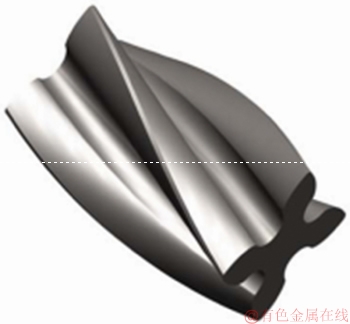
Figure 1 4-lobe aluminum alloy helical surface rotor
2.2 Simulation of extrusion process
Numerical simulations of the extrusion process are analyzed by means of the finite element method with a professional forming simulation software DEFORM-3D. Firstly, the extrusion model is established, which includes extrusion ram, extrusion cylinder, extrusion die and billet. And the three dimensional models of these components are created in 3D model software INVENTOR, then, they are imported into DEFORM-3D, which is shown in Figure 2. Some parameters need to be set up before the simulated extrusion experiment begins, as summarized in Table 1.

Figure 2 Extrusion simulation model
3 Results and discussion
3.1 Metal flow in helical die land
The simulation steps are used to represent the stroke in the actual extrusion process. The billet is taken as the analysis object, and the generation process of the helical surface is observed from the positive direction of the Z axis in the case of different simulation steps, as shown in Figure 3, so as to observe the flow of metal more clearly.
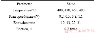
Table 1 Influencing parameter on forming process
The 55 steps are the stage of diversion and tooth dividing, which belongs to the stage of cylindrical extrusion (Figure 3(a)). The 58 steps are that the billet begins to enter the helical die land of the extrusion die, due to the existence of the helix angle, the profile begins to twist, it means that the helical surface will be produced (Figure 3(b)). The 66 steps are that the billet has entered into the helical die land, which belongs to the initial forming stage (Figure 3(c)). And in that stage, the twist angle has been formed already. The 77 steps illustrate the flow of aluminum alloy billet in the helical die land, which belongs to complete forming stage (Figure 3(d)).

Figure 3 Extrusion process under different simulation steps:
3.2 Analysis of influencing parameters
When the twist angle is sufficiently large, the helical surface of the aluminum alloy may not be extruded due to the large extrusion load required. Therefore, extrusion load is one of the key points in the study. The flow of metal and process parameters also play an important role in the extrusion forming of 4-lobe aluminum alloy helical surface rotor.
Especially, the friction coefficient is set to be fixed, considering that there is no lubrication or surface coating for the die. In order to get a high-accuracy rotor, extrusion process parameters influencing the forming process are analyzed, as shown in Table 2. In this paper, different initial temperatures, different ram speeds, different extrusion ratios and different billet length are analyzed to get a set of optimal parameters.
Table 2 Experimental parameters
3.2.1 Extrusion temperature
In order to analyze extrusion temperature, the other parameters should be set to be fixed. And the ram speed is 1.1 mm/s, the extrusion ratio is 22, the billet length is 600 mm. Figure 4 shows the temperature distribution of the billet during helical extrusion process at an initial extrusion temperature of 460 ��C.
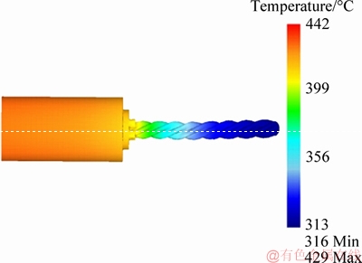
Figure 4 Temperature field distribution of billet during helical extrusion process
The temperature distribution of the billet in the extrusion cylinder is approximately unchanged during the extrusion process, and the temperature distribution in the die shows a general downward trend, but the downward gradient is small. The temperature of helical profile is different in each section after extrusion die, and the longer the extrusion length, the lower the temperature of helical profile extrusion products.
The temperature variation of the billet in the extrusion process under different initial extrusion temperatures is shown in Figure 5.

Figure 5 Temperature variation of billet under different initial temperatures
The temperature change trend of the billet in the extrusion process is consistent. The temperature begins to decrease when the billet gets into the die. However, there is a slight rise in temperature as long as the billet gets into helical die land. Due to the friction between the helical surface and the inner wall of the die, there is a strong thermal effect. When the billet gets out of the die, the temperature decreases linearly.
It can be seen from Figure 6 that when the temperature is 400 ��C, the maximum extrusion load is about 13 MN. One possible reason is that when the temperature is relatively low, the precipitation strengthening phase in the bullet has not been completely dissolved into the solute atoms, so that the softening effect is not optimal, and the macroscopic expression is that the extrusion force is larger than the extrusion force under other high temperature conditions. When the temperature is 480 ��C, the maximum extrusion load is about 10 MN. For 4-lobe aluminum alloy helical surface extrusion, extrusion temperature is not as high as possible. Moreover, Figure 5 shows that the higher initial extrusion temperature, the higher the temperature of the billet at the die exit, which has influence on the twist angle due to the springback of the helical profile. The twist angle will be discussed in the next part.

Figure 6 Variation of extrusion load under different initial temperatures
3.2.2 Ram speed
The same way is used to analyze the ram speed. And the extrusion temperature is 430 ��C, the extrusion ratio is 22, the billet length is 600 mm.
It can be seen from Figure 7 that the flow velocity of the billet in the extrusion cylinder is basically unchanged, and the velocity direction is z axis positive direction. When the billet enters the helical die land, the flow velocity direction varies with time along the helical surface. And the angle between the velocity direction of the helical surface and the z axis is the helix angle of the point.

Figure 7 Flow field distribution in helical extrusion process
Figure 8 shows the flow field distribution in the step 60 and the billet is observed in the z axis. It can be seen that the speed of the center part is higher than that of the four teeth around it when the billet enters the die land. This is because when the billet enters the die land, the four teeth around it need to rotate, and the rotating speed is a part of its axial speed. However, there is little difference between the velocity at the center and the axial velocity, so the center of the helical profile will be a little longer than the surrounding parts.
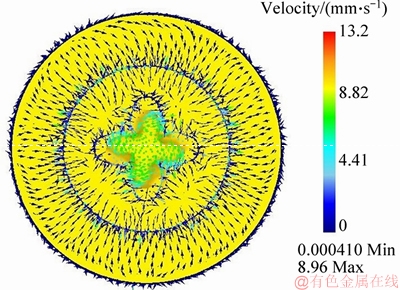
Figure 8 Distribution of flow field in z axis (step 60)
The Figure 9 shows that if the flow velocity is projected on the x-y plane, it is a concentric circle rotating clockwise. The outer circle is the size of the top circle of the helical profile. The rotation direction of the concentric circle is related to the rotation direction of the helical profile, and the distribution of concentric circle is very uniform, indicating that the velocity of each part of the extrusion product is relatively uniform, which is conducive to the forming of helical profiles. Because if the distribution of the velocity of each part of the profiles is uneven, it will lead to profiles such as waves, which will reduce the surface quality of the extruded products.
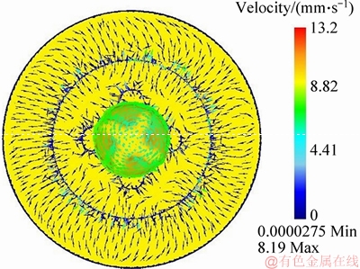
Figure 9 Distribution of flow field in z axis (step 137)
The exit velocity variation of billet under different ram speed is shown in Figure 10.
When the ram speeds are 0.2, 0.5, 0.8 and 1.1 mm/s respectively, the calculated exit velocity are 4.4, 11, 17.6 and 24.2 mm/s, respectively, and they are roughly consistent with the simulation data (Figure 10).

Figure 10 Variation of exit velocity under different ram speed
Therefore, the simulation data could be used as the reference value of special tractor (Figure 14) moving speed. What is more, the greater the ram speed is, the greater the exit velocity fluctuation is.
3.2.3 Extrusion ratio
The initial extrusion temperature is set to be 430 ��C, the ram speed is 0.5 mm/s, and the billet length is 300 mm.
Because the aluminum alloy helical surface cross-section area is fixed, extrusion ratio can be changed by changing the diameter of the billet. Therefore, extrusion ratios are set to be 10:1, 13:1, 22:1 and 31:1,respectively, which are equivalent to do experiment in the extrusion machine of 16, 20, 25 and 36 MN. The variation of extrusion load under different extrusion ratios is shown in Figure 11. The maximum extrusion load is within the extrusion capacity of the corresponding extruder, that is to say, the extruder of 16 MN can complete the extrusion of the 4-lobe aluminum alloy helical surface rotor. The larger the extrusion ratio is, the greater the extrusion load is required. The maximum extrusion loads required for extrusion ratios of 31:1 and 10:1 are 16 and 4 MN, respectively, and the difference is 12 MN, which shows that the extrusion ratio has a significant influence on the extrusion load. And a small capacity of extruder should be chosen in the case of meeting the requirements.
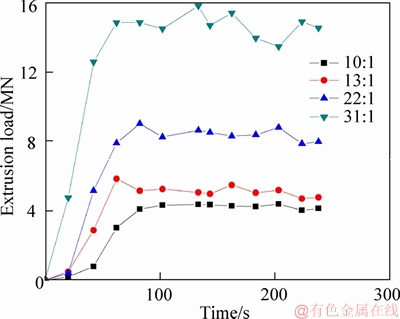
Figure 11 Variation of extrusion load: different extrusion ratio
3.3 Actual experiment detail
The extrusion experiment of 4-lobe aluminum alloy helical surface rotor is carried out in the state key laboratory of high performance complex manufacturing of Central South University, China, where the extruder is a 25 MN oil pressure double action forward backward horizontal aluminum extrusion press. And the die is designed according to the specification of the 25 MN extruder, so the extrusion ratio is about 22, and there is a detailed description about the helical extrusion die in Section 3.4.
The process is a forward hot extrusion, which is similar to the conventional extrusion process. The biggest difference is the extrusion die, especially the die land, as shown in Figure 12. The most difficult thing is the manufacturing of the die, because it is very difficult to process a helical surface on a metal cutting machine. A special program is applied to an electrical discharge machining, which can process a helical inner surface. And the machining process of the die is shown in Figure 13.
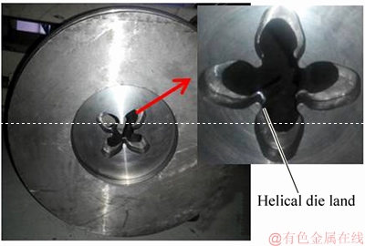
Figure 12 Helical extrusion die
The design of diversion tooth separation in the die is beneficial to metal flow in the forming process of tooth profile. And the design of helical die land makes the helical surface rotor formed. Therefore, the special traction mechanism has been designed and used in the experiment, which can rotate freely, as shown in Figure 14. It can be rotated with the helical profile to ensure the smooth progress of the extrusion process and the straightness of the helical profile.
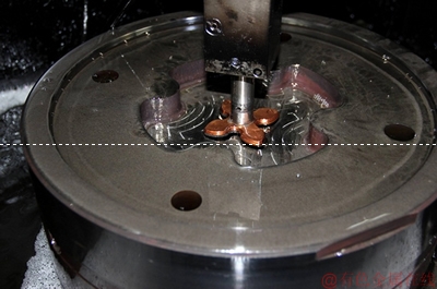
Figure 13 Machining process of die
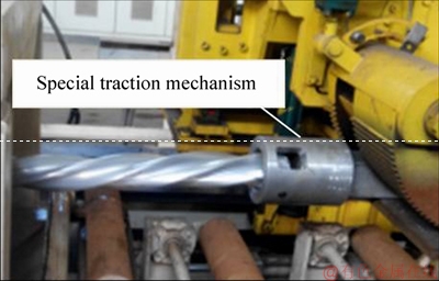
Figure 14 Special traction mechanism
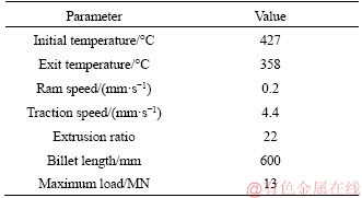
Based on numerical simulation analysis, the optimal extrusion process parameters are chosen as the experimental parameters, as shown in Table 2. When the billet and the die are lifted from the heating furnace, they are exposed to the air, and the temperature can be measured at about 427 ��C. The ram speed is set to be 0.2 mm/s, the traction speed is set to be 4.4 mm/s, the temperature of the extrusion profile at the exit of the die is measured at about 358 ��C. And the experiment is done successfully. The actual extrusion load and simulated load are shown in Figure 15.
In the actual extrusion experiment, the maximum extrusion load reaches about 13 MN, and the maximum extrusion load of the simulation test is about 11.5 MN. Moreover, they have nearly the same time to reach a maximum value and then they have the same trend, which further illustrates the accuracy of the helical surface extrusion parameters.
From the analysis of extruded product, aluminum alloy helical surface is very smooth, the four teeth are full, and in the length direction, the distribution of the twist angle is very uniform, and the value of the twist angle is also close to the value of the required twist angle. Therefore, the extruded product is in line with the practical requirements, as shown in Figure 19 (the right one).

Figure 15 Extrusion load of actual and simulated experiment
3.4 Twist angle
3.4.1 Problem of twist angle
There are two experiments that have been investigated to get required 4-lobe aluminum alloy helical surface rotor. The biggest problem that has occurred is that the twist angle of the extruded product is less than the twist angle of the design. In order to increase the twist angle of the extruded product, lots of work has been done about redesigning the die structure, which is the focus of this problem. To study the influence of the die structure on the twist angle, the friction coefficient remains to be unchanged. The 3D models of the first and the modified die structure are shown in Figures 16 and 17.
One of the reasons for the decrease of the twist angle is that the temperature of extruded product decreases rapidly (Figure 5) when it gets out of the die, and then the twist angle of extruded product of 6063 aluminium alloy happens with spring back, which is the key point of the problem. There are three measures that have been used in the structure of the modified die.


Figure 16 3D model of first die structure
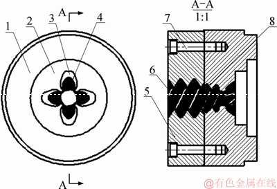
Figure 17 3D model of modified die structure (1��Upper die; 2��Cylindrical grooves; 3��Diversion hole; 4��Die land; 5��Lower die; 6��Primary twist angle appliance; 7��Cylindrical pin; 8��Two stage twist angle appliance)
1) The porthole die is changed to the advection die;
2) The structure of twist angle appliance is added to the advection die;
3) The compensation method is applied to the structure design of advection die land.
3.4.2 Structure of dies and twist angle appliance
The first die structure (Figure 16) is a porthole die. Its upper die divides the aluminum alloy billet into four parts, and then the billet gets into the chamber of the lower die, finally, the billet enters into die land and the helical surface is formed.
However, the modified die is an advection model, and the die land is in the upper die (Figure 17).
What is more, there is a tooth separated structure before the die land, which means there are four teeth already when the billet enters into the die land. And there are primary twist angle appliance and two-stage twist angle appliance behind the die land. The primary twist angle appliance is the same as the die land except for the size of diameter. And it extends 1.5 mm by equal distance in the radial direction compared to the die land. The two-stage twist angle appliance extends 2 mm by equal distance compared to the primary appliance. And it does not have a rejecting structure which provides a lot of resistance.
Figure 18 shows the modified die land which is installed on the extruder and the structure of the die land and the appliance can be seen clearly. The helical directions of the appliances are the same with the die land. It is just that the appliances�� sizes are getting bigger. Therefore, both of them are designed to prevent the spring back of the twist angle, and they have achieved a good result.
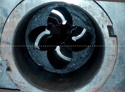
Figure 18 Photo of modified die land
3.4.3 Compensation method
In the first die land, the twist angle is designed as 60��/100 mm and the left one (Figure 19) is extruded from the first die, and its twist angle is 33��/100 mm. As a result, the twist angle of the extruded product is less than the designed twist angle and it has a huge springback. Therefore, the compensation method is applied to the next die land, which means the springback of the twist angle is allowed.
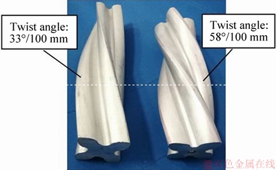
Figure 19 Helical profiles with increased angle
Actually, it is still not clear about the springback rule of helix angle. First of all, what should be done is to increase the twist angle of the die and it is doubled compared with the required twist angle. And the springback rule of helix angle is being studied now through finite element numerical simulation and basic experiment.
In the modified die land, the twist angle is designed as 120��/100 mm. The designed twist angle has already expanded two times and the right one (Figure 18) is extruded from the modified die under the condition of the same extrusion parameters. Its twist angle is 58��/100 mm, which achieves an increase of about 76% compared to the first trials. Furthermore, it is very close to the actual required twist angle (60��/100 mm).
3.5 Mechanical properties and micro-structural characteristics of helical profiles
The mechanical properties of the helical profiles are measured by measuring the tensile properties and hardness of the helical profiles. According to the standard of tensile sample, the tensile specimens are obtained from the central and edge parts of the helical profile, as shown in Figure 20, where I and II denote the sampling positions of the two parts, respectively.
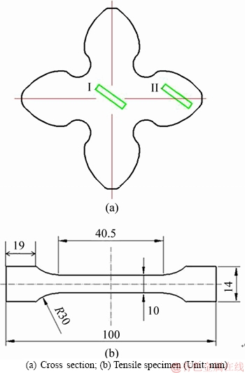
Figure 20 Profiles of helical profile:
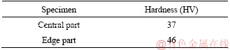
The data of the mechanical properties are shown in Table 3. The tensile strength and yield strength of the edge parts are larger than those of the central ones, and the elongation of the edge parts are smaller than the central ones. In addition, the hardness of the helical profile has also been tested, as shown in Table 4.
The hardness of the edge part is HV 9 more than the hardness of the central part. This deviation of hardness is consistent with the deviation of the mechanical properties of the helical profiles.
Table 3 Mechanical properties of helical profiles

Table 4 Hardness of helical profiles
It should be noted that the helical profile has not undergone any heat treatment process after extrusion, that is, it has been in a natural aging state, and its mechanical properties and hardness can be improved by heat treatment process.
In order to explain the performance differences between the central part and the edge part of the helical profile, the microstructures of the same section of the helical profiles are observed by metallurgical microscope experiments, and there are two metallographic graphs shown in Figure 21.
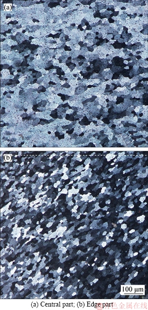
Figure 21 Metallographic graphs of helical profiles:
The grain size of edge part is significantly smaller than the size of the central part grain. As for the uniformity of grain distribution, the edge part is better than the central part. Therefore, fine grains and better uniformity of grain distribution can effectively prevent dislocation and intergranular slip, and that is why the mechanical properties and the hardness of edge part are better than those of central part.
Moreover, the reason why the grain of the edge part can be refined is that the aluminum alloy at the edge part is rotated in the process of helical extrusion, due to the friction between the edge part and inner wall of helical die land. Therefore, severe shear deformation has been occurred, which results in the breakage of original coarse grain and the increase of dislocation density. While the aluminum alloy in the central part has only a small amount of shear movement, and the coarse grains are more numerous, so the central part has relatively low performance.
3.6 Outlook
Obviously, the modified die structure has a positive and significant effect on the increment of twist angle, and the optimization of the die structure in the process of forming the helical surface is worth considering. However, it is difficult to popularize or become industrialized when the required twist angle changes. In the further research, maybe a tailored alloy or a more intelligent die device can achieve that.
4 Conclusions
1) A forward hot extrusion process has been proposed for manufacturing 4-lobe aluminum alloy helical surface rotor. It can replace the mechanical roughing process of helical surfaces and significantly improve the production efficiency and material utilization rate.
2) In the helical extrusion experiment, the extrusion parameters are determined within a certain range. The extrusion temperature of 6063 aluminum alloy is best set from 430 to 460 ��C in consideration of the exit temperature of the billet in the die and energy saving. And the extrusion speed is best set from 0.2 to 0.5 mm/s. The extrusion ratio can be chosen with a smaller extrusion ratio.
3) The biggest innovation of this paper lies in the die structure. And the modified die has a positive effect, the twist angle has an increase of about 76% compared to the primary die structure, and the extruded product almost meets requirement. The mechanical properties and hardness rules of extruded helical profiles are realized as: the edge part is superior to the central part.
4) However, there is still a lot of work to do in the research of the extrusion forming of 4-lobe aluminum alloy helical surface rotor when the required twist angle changes.
References
[1] LIU Hou-gen, LI Zhi-bao, LI Cheng-jia. Design and manufacturing research of roots mechanical supercharger new rotors [J]. Modern Manufacturing Engineering, 2014, 8: 112-116. DOI: 10.16731/j.cnki.1671-3133.2014.08.013.
[2] INGLE P D, NARKHEDE B E. A literature survey of methods to study and analyze the gating system design for its effect on casting quality [J]. Materials Today: Proceedings, 2018, 5(2): 5421-5429. DOI: org/10.1016/j.matpr.2017. 12.129.
[3] WEI Wei, JIANG Peng, TANG Yong-fu. Analysis on forging defects of aluminum alloy forging with rib [J]. Forging & Stamping Technology, 2012, 4(37): 18-21. DOI: 10.3969./ j.issn.1000-3940.2012.04.004.
[4] FOUAD M, EL-GARAIHY W H, AHMED M M Z, EL- SAYED S M M, SALEM H G. Influence of multi-channel spiral twist extrusion (MCSTE) processing on structural evolution, crystallographic texture and mechanical properties of AA1100 [J]. Materials Science and Engineering: A, 2018, 737: 166-175. DOI: 10.1016/ j.msea.2018.09.039.
[5] KUBOKI T, ISHIKAWA M, KAJIKAWA S, MURATA M. An extrusion method of tube with spiral inner fins by utilizing generation of spiral outer fins/grooves [J]. CIRP Annals, 2018, 67: 305-308. DOI: 10.1016/j.cirp. 2018.04.023.
[6] IVANISENKO Y, KULAGIN R, FEDOROV V A, MAZILKIN A, SCHERER T, BARETZKY B, HAHN H. High pressure torsion extrusion as a new severe plastic deformation process [J]. Materials Science and Engineering: A, 2016, 664: 247-256. DOI: 10.1016/j.msea.2016.04.008.
[7] CAI Chen, YAN B, LASZLO S T, FUNDENBERGER J J. Microstructure and strain in protrusions formed during severe plastic deformation of aluminum [J]. Materials Letters, 2015, 159: 253-256. DOI: 10.1016/j.matlet.2015.07.008.
[8] CHAUBEY S K, JAIN N K. Exploring WSEM process for manufacturing meso helical and bevel gears [J]. Materials Today: Proceedings, 2018, 5(9): 18552-18561. DOI: 10.1016/j.matpr.2018.06.198.
[9] SNOPI
 KI P, TASKI T, MATUS K, MATUS K, RUSZ S. Microstructure, grain refinement and hardness of Al�C3%Mg aluminium alloy processed by ECAP with helical die [J]. Archives of Civil and Mechanical Engineering, 2019, 9(2): 287-296. DOI: 10.1016/j.acme.2018.11.003.
[10] ZHANG Yu, YAN Hong-zhi, ZENG Tao. Tooth surface geometry optimization of spiral bevel and hypoid gears generated by duplex helical method with circular profile blade [J]. Journal of Central South University, 2016, 23(3): 544-554. DOI: 10.1007/s11771-016-3101-5.
[11] YANG Guang, ZHANG Kang-sheng, HU Zheng-huan. Feasibility study on screw compressor driven rotor with fixed cross rolling [J]. Journal of Northeastern University, 2015, 12(36): 1785-1789. DOI: 1005-3026(2015)12-1785- 05.
[12] KIM J G, LATYPOV M, PARDIS N. Finite element analysis of the plastic deformation in tandem process of simple shear extrusion and twist extrusion [J]. Materials & Design, 2015, 83: 858-865. DOI: 10.1016/j.matdes.2015.06. 034.
[13] HWANG Y M, CHANG C N. Hot extrusion of hollow helical tubes of magnesium alloys [J]. Procedia Engineering, 2014, 81: 2249-2254. DOI: 10.1016/j.proeng. 2014.10.316.
[14] PARK Y B, YOON J H, YANG D Y. Finite element analysis of steady-state three-dimensional helical extrusion of twisted section using recurrent boundary conditions [J]. International Journal of Mechanical Science, 1994, 36(2): 137-148. DOI: 10.1016/0020-7403(94)90081-7.
[15] PARK Y B, YANG D Y. Investigation into non-steady-state three-dimensional helical extrusion of twisted sections by the rigid-plastic finite element method [J]. Engineering Computations, 1997, 6(14): 649-668. DOI: /10.1108/ 02644409710180509.
[16] KHODDAM S, FARHOUMAND A, HODGSON P D. Axi-symmetric forward spiral extrusion, a kinematic and experimental study [J]. Materials Science and Engineering A, 2011, 528: 1023-1069. DOI: 10.1016/j.msea.2010.09. 062.
[17] KHODDAM S, FARHOUMAND A, HODGSON P D. A kinematics study of variable lead axisymmetric forward spiral extrusion [J]. Materials Science and Engineering A, 2012, 550: 167-175. DOI: 10.1016/j.mmsea.2012.04.053.
[18] KHODDAM S, FARHOUMAND A, HODGSON P D. Upper-bound analysis of axi-symmetric forward spiral extrusion [J]. Mechanics of Materials, 2011, 43: 684-692. DOI: 10.1016/j.mechmat.2011.07.009.
[19] FARHOUMAND A, HODGSON P D, KHODDAM S. Multiple pass axi-symmetrical forward spiral extrusion of interstitial-free (IF) steel [J]. Materials Science & Engineering A, 2013, 579: 217-225. DOI: 10.1016/j.msea. 2013.05.034.
[20] YAGITA T, KUBOKI T, MURATA M. Formability improvement by die-bearing grooves in tube extrusion with spiral inner projections [J]. Procedia Engineering, 2014, 81: 641-646. DOI: 10.1016/j.proeng. 2014.10.053.
[21] SAPANATHAN T, KHODDAM S, ZAHIRI S. Spiral extrusion of aluminum/ copper composite for future manufacturing of hybrid rods: A study of bond strength and interfacial characteristics [J]. Journal of Alloys and Compounds, 2013, 571: 85-90. DOI: 10.1016/j.jallcom. 2013.03.210.
[22] FREDERIC B B, BACHI F B , HAROUN Y , DIGNE M , CORRE V L. Helical extrusion of unsymmetrical multi- lobed catalyst supports: United State, Patent Pub.No. US2015/0174571AL [P]. 2015-06-25.
[23] KHALIFA N B, TEKKAYA A E. Newest developments on the manufacture of helical profiles by hot extrusion [J]. Journal of Manufacturing Science and Engineering, 2011, 133: 101-108. DOI: 10.1115/1.4005116.
[24] KHALIFA N B, BECKER D, SCHIKORRA M, TEKKAYA A E. Recent developments in the manufacture of complex components by influencing the material flow during extrusion [J]. Journal of Manufacturing Key Engineering Materials, 2008, 367: 55-62. DOI: 10.4028/www.scientific. net/KEM.367.55.
(Edited by FANG Jing-hua)
���ĵ���
��Ҷ���Ͻ�������ת�������ȼ�ѹ���ι����о�
ժҪ����Ҷ���Ͻ�������ת�ӹ㷺Ӧ���ڹ�ҵ�У����е��ѹ������ͳ�ӹ����Ͻ�������Ĺ��մ��ڷ�ʱ�ͳɱ��ߵ����⡣Ϊ��ʹ���칤�ո������;��ã�����������ȼ�ѹ����������4Ҷ���Ͻ�������ת�ӡ��������õIJ���Ϊ6063���Ͻ𣬶�������ij��ι��̽�������ֵ����ͼ�ѹʵ�顣����DEFORM-3D�����������ȼ�ѹ���ι��̽���������Ԫģ�⡣�ڷ��淽���Ļ����ϣ��о��˲�ͬ�ļ�ѹ�������缷ѹ�¶ȡ���ѹ�ٶȡ���ѹ�ȣ��Լ�ѹ���̵�Ӱ�졣������ֵģ������ѡ������������м�ѹʵ�顣ʵ����������ת�ӱ���⻬��������䱥�����ڳ��ȷ�����Ťת�Ƿֲ����ȣ�Ťת�ǵ�ֵ����ƽǵ�ֵ����һ�¡��ܹ��ﵽ����ý������Ҫԭ����ʹ���˸Ľ����ģ�߽ṹ����Ťת�ǵ������л�����������Ӱ�죬��ˣ�Ťת��������Լ76%����֤�˸Ľ���ģ�߽ṹ��
�ؼ��ʣ�6063���Ͻ������棻�����ȼ�ѹ��Ťת�ǣ�ģ�߽ṹ
Foundation item: Project(zzyjkt2014-09) supported by the National Key Laboratory of High Performance and Complex Manufacturing, China; Project(2015GK3006) supported by Key R&D Program of Science and Technology Department of Hunan Province, China
Received date: 2018-08-23; Accepted date: 2018-12-05
Corresponding author: LIU Hou-gen, PhD, Professor; Tel: +86-13974823102; E-mail: lhg.csu@126.com; ORCID: 0000-0002-1952- 714X

