J. Cent. South Univ. Technol. (2011) 18: 600-609
DOI: 10.1007/s11771-011-0737-z
Development of Chinese large-scale space end-effector
LIU Hong(刘宏), TAN Yi-song(谭益松), LIU Yi-wei(刘伊威),
JIE Dang-yang(介党阳), GAO Kai(高凯), CAI He-gao(蔡鹤皋)
State Key Laboratory of Robotics and System, Harbin Institute of Technology, Harbin 150001, China
? Central South University Press and Springer-Verlag Berlin Heidelberg 2011
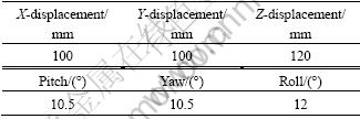
Abstract: In order to achieve large tolerance capture and high stiffness connection for space payload operations, a Chinese large-scale space end-effector (EER) was developed. Three flexible steel cables were adopted to capture the payload with large capture allowance. Ball screw transmission mechanism and plane shape-constraint four bar linkage mechanism were utilized to connect the payload with high stiffness. The experiments show that capture tolerances in X, Y, Z, Pitch, Yaw, Roll directions are 100 mm, 100 mm, 120 mm, 10.5°, 10.5°, 12°, respectively. The maximum connection stiffness is 4 800 N?m. The end-effector could meet the requirements for space large tolerance capture and high stiffness connection in the future.
Key words: large tolerance capture; high stiffness connection; end-effector; flexible steel cable; ball screw; four bar linkage
1 Introduction
The international space station (ISS) proposed by US president Reagan has made great success. Sixteen countries including America, Russia, Canada, Japan and the European Union conducted lots of scientific experiments on the Alpha space station and made many achievements. As a means to exploit space recourses, the ISS provided a long-term on-orbit opportunity for human being to observe the earth from space. But until now, China doesn’t have its own space station, nor could participate in the Alpha space station program. With the increasing demand on space technology, space resources and space scientific researches, it has been the order of the day to set up China’s own long-term on-orbit space station.
The Alpha space station is 423 t in mass, 108 m in length and 88 m in width. To assemble and maintain so huge a thing would be very difficult in space and could not be accomplished at all depending solely on the astronauts themselves. Moreover, it is necessary to supply replenishment to the manned space station periodically. However, the transfer vehicle cargo (TVC) transporting replenishment varied in mass from several tons to tens of tons and was out of the capability of astronauts either. So, it is a necessity for space station construction to develop a large-scale space manipulator to substitute for astronauts to assemble and maintain the space station. Presently, there were three kinds of manipulators serving on the ISS [1-2]. The first one was the space station remote manipulator system (SSRMS) [3-8] manufactured by Canada and assembled on the US segment of ISS. The SSRMS consisted of a 7-DOF robotic arm (17.6 m) and two end-effectors (EER) on each end of the arm. The Canada SSRMS mainly accomplished space station assembly and maintenance, satellite release and retrieval, and replenishment handling. Its maximum load capacity was 116 000 kg. The second one was the Japanese experiment module remote manipulator system (JEMRMS) [9-10] manufactured by Japan National Space Development Agency (NSDA) and assembled on the Japanese experiment module segment of ISS. The JEMRMS comprised 6-DOF robotic arm and an end-effector on the front end of the arm. The end- effector JEMRMS was similar to Canada’s end-effector and adopted the same grapple interface (GI) which increased the modularity and interchangeability of ISS. The maximum load capacity of JEMRMS was 6 000 kg. The last one was the European robot arm (ERA) [11-12] manufactured by the European Space Agency and assembled on the Russian segment of ISS. The ERA was composed of 7-DOF robotic arm (10.4 m) and two end- effectors on each end of the arm. Its lateral and axial misalignments were 25 mm and 25 mm, respectively. The roll, yaw and roll misalignments were all 3°. The ERA end-effector was more suitable for stationary payload handling and its maximum load capacity was 8 000 kg.
2 Overall of system
Figure 1 shows the concept scenario of Chinese remote manipulator system.
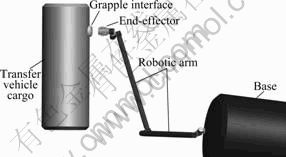
Fig.1 Concept scenario of Chinese remote manipulator system
According to functions of the space remote manipulator system, the principal requirements of the end-effector are listed as follows:
1) To assist in space station assembly;
2) To capture, hold and release free-flying payload;
3) To perform attached payload servicing;
4) To support space station maintenance function;
5) To provide a stable platform for astronaut extra- vehicle activity (EVA);
6) To have information feedback ability.
Chinese space EER and grapple interface (GI) designed according to the requirements above are shown in Fig.2.
EER consists of three subsystems for different functions, namely snare, rigidize and latch subsystem. GI includes one grapple shaft, three location cams and four electrical connections mainly, which matches with EER’s subsystems individually.
3 Snare subsystem design
3.1 Snare mechanism
The function of the snare subsystem is to capture the grapple shaft on GI to restrict its movement in space. Larger capture tolerance decreases requirements on the robotic arm.
Figure 3 shows the snare mechanism. The snare subsystem was mounted on the supporting shell. The motor drove through a harmonic drive gear to an inner gear attached to a rotating ring. One end of the three snare cables were mounted on the rotating ring and the other end on the fixed ring. As the motor/harmonic gear drove the rotating ring with respect to the fixed ring, the snare cables contacted the grapple shaft and wrapped around it. The area enclosed by the snare cables was just the capture envelope. The Kaydon thin wall bearing increased the capture envelope enormously. Double winding motor was adopted in the subsystem which increased the redundancy of the driving system to meet the hard space environment. And also to confirm the performance of thin wall bearing in space, structural components connected to it were all manufactured from titanium which had the close thermal expansion to the bearing and had small mass. The capture procedure is shown in Fig.3. Once a successful snare had been completed, the brake was engaged and the rigidize subsystem started to work.
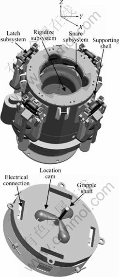
Fig.2 Chinese space EER and GI
3.2 Sensor system
In order to guarantee the reliability, safety and intelligence of space operation and accomplish position, velocity and impedance control methods, the end-effector needed a few of sensors to get system information feedback.
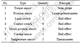
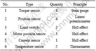
Table 1 lists all the sensors integrated in the system. Of all the sensors, the torque sensor and position sensor were of particular importance to the system. When accomplishing space operation, the torque sensor could reflect the magnitude of snare forces to provide the operation information for the astronaut to avoid accidents. The torque sensor was based on shear strain theory. Eight strain gauges made up two full bridges, which could compensate temperature and transverse forces. The strain analysis and shape optimization were done by the finite element method (FEM). Special attention was given to the overload protection of the sensor in designing period. The sensor had eight beams, four of which were used to paste the strain gauges and the others were used for the overload protection. The position sensor could be used to measure the current wrapping position of snare cables accurately to supply the position information for the system. Moreover, there were two Hall limit switches on each end of the rotating ring to prevent it from over-traveling and to increase the reliability of the system. Also, there were three Hall sensors in the motor to detect the position of motor rotor, which enhanced the redundancy of the system. A temperature sensor was mounted on each electrical board to detect the temperature variation of the system.
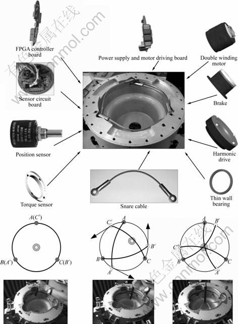
Fig.3 Snare mechanism
Table 1 Sensors integrated in snare subsystem
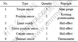
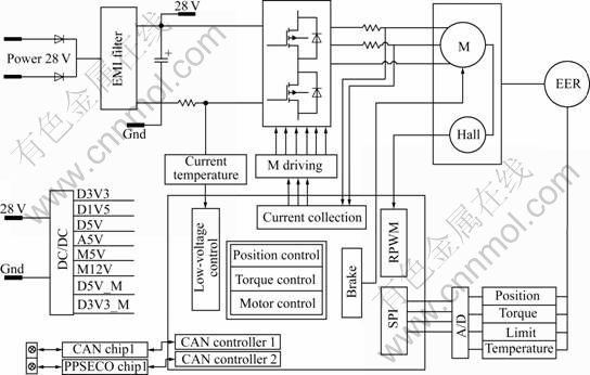
Fig.4 Control diagram of snare subsystem
3.3 Control and driving modular
Snare subsystem adopted independent control and driving system which communicated with the space station manipulator system through CAN bus. It had four individual subunits: power supply unit (PSU), controller unit (COU), motor servo unit (MSU) and sensor conditioning unit (SCU). Figure 4 shows the control diagram of the snare subsystem.
In order to prevent it from damage of space single particle, the control and driving modular was encapsulated in a 6 mm-thick aluminum shell. The snare control and driving system was also applicable to rigidize and latch subsystem which increased the interchangeability and reliability of the whole end-effector.
4 Rigidize subsystem design
4.1 Rigidize mechanism
After a successful capture, the rigidize subsystem began to drag the payload from initial position to final position. During the procedure, it eliminated payload attitude errors in all directions towards the end-effector and paved the way for the latch subsystem. Figure 5 shows the working scenario of the rigidize subsystem.
Figure 6 shows the rigidize mechanism. Brushless motor drove the ballscrew through a harmonic drive gear. The rotating ballscrew compelled the nut mounted inside the torque sensor to drag the snare subsystem down as well as the payload attached to the snare cables along three sets of linear bearings mounted on the supporting shell. The initial retraction caused the snare cables to slide alone the grapple shaft until the underside of the shaft. Continuous drag made the payload move towards the end-effector removing pitch and yaw misalignments. With the retraction going on, location cams on the end-effector contacted with pockets on GI to eliminate roll misalignment owing to the rigidize force. The specific procedure is indicated in Fig.7. When reaching the final position, GI impacted on the six contact switches on EER to give out the stopping signals. When the rigidize control module detected the signals, the rigidize subsystem stopped and the brake was engaged. The last latch subsystem began to work.
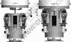
Fig.5 Working scenario of rigidize subsystem
4.2 Sensor system
In order to guarantee the reliability of the retraction, especially to prevent the harmful bump to the system, the rigidize subsystem utilized abundant sensors to return the system states real time. Table 2 lists all the sensors integrated in the rigidize subsystem.
Fig.6 Rigidize mechanism
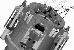
Fig.7 Roll misalignment eliminated by EER
Table 2 Sensors integrated in rigidize subsystem
The torque sensor was to gauge the dimension of the rigidize force. It was especially important when the location cams contacted with the pockets on GI. Through the magnitude, the force was gotten whether there was any deflection. The torque was also analyzed by FEM. Another important parameter during the retraction was the position of snare subsystem. The linear potentiometer mounted on the supporting shell could measure this parameter precisely.
A working condition experiment device was designed to calibrate the performance of the rigidize torque sensor (Fig.8). During the calibration, the applying loads and corresponding output voltages were recorded. Based on the least-square algorithm theory, the relation between the applying loads and the output voltages could be deduced. Table 3 lists the performance of the rigidize torque sensor.
The contact switch was to detect whether GI and EER contacted firmly. An individual contact switch of special design could detect the plane contact effectively. And the six contact switches could work jointly to pick out misinformation such as GI deflection accurately, which ensured the precision and reliability. Figure 9 shows the contact switch. The logic relation of contact switch is
output= (1)
(1)
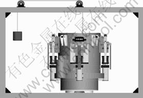
Fig.8 Working condition experiment device
Table 3 Performance of rigidize torque sensor
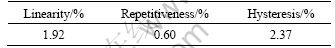
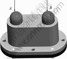
Fig.9 Contact switch
5 Latch subsystem design
5.1 Latch mechanism
It was not very reliable for some large payloads to depend solely on the force supplied by the rigidize subsystem (<1 400 N). Moreover, some TVCs were needed to get power and control signals from EER. The latch subsystem could meet demands above.
The latch mechanism is shown in Fig.10.
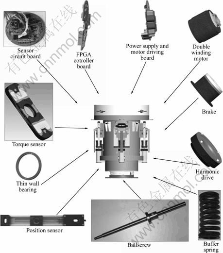
Fig.10 Latch subsystem mechanism
The motor drove ring gear mounted on the thin wall bearing through a harmonic drive gear and a pair of gears. The ring gear drove four ballscrew nuts to rotate simultaneously. The nut compelled the ball screw to slide forward along the linear bearing. During the linear portion of linear support, the left and right latch jaws kept closed due to the shape confinement, as indicated in Fig.11(a). With the ballscrew going on sliding, the left and right latch jaws arrived at the sloping portion of the linear support. The left and right latch jaws became open and locked GI firmly for lack of shape constraint, as shown in Fig.11(b). Each pair of latch jaws could provide about 4 000 N lock force. The overall 16 000 N lock force could enhance the connecting stiffness between EER and GI greatly. Finally, with the ballscrew going on moving, electrical socket and electrical plug installed in EER and GI respectively mated with each other to transfer power and control signals, as shown in Fig.11(c). The buffer spring absorbed the shock generated during the movement to protect the system from the damage. After the whole procedure, every spring was compressed by 1.5 mm and supplied about 1 000 N preload force which was extremely important to relieve backlash between EER and GI.
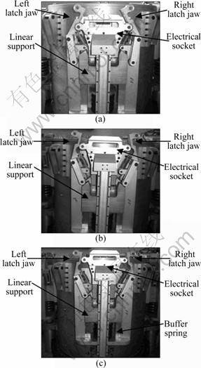
Fig.11 Working scenario of latch subsystem: (a) Rising; (b) Opening; (c) Latching
5.2 Sensor system
To work properly, not only the latch subsystem but also the sensor system had a high demand on the mechanism itself. The latch torque sensor had the same function as the two systems mentioned above. There was one torque sensor in each of the four latch jaws which could provide redundant information for the system. High precision linear potentiometer could detect the position of the electrical socket accurately to provide reliable position feedback. Four potentiometers worked simultaneously, increasing the reliability and redundancy of the system and satisfying the space requirements. Table 4 lists all the sensors integrated in the latch subsystem.
Table 4 Sensors integrated in latch subsystem
6 Experimental study
6.1 Control strategy
Manipulating envelope is of great importance in space operation. Larger envelope could relieve the burden of robotic arm and increase the probability of space activity. The manipulating envelope of Chinese EER was given special attention and a ground zero gravity testbed was designed.
Figure 12 shows the EER manipulating a free-flying payload [13-14].
1) EER approached GI through robotic arm under the vision servo system (individual system).
2) EER adjusted its attitude according to the GI position and orientation information given by the vision servo system and prepared to capture.
3) The snare subsystem captured the GI grapple shaft to make sure that GI did not escape, as shown in Fig.12(a).
4) The rigidize subsystem translated the GI and payload forward until getting the contact switches and position sensor information feedback, as shown in Fig.12(b).
5) The latch subsystem locked GI firmly and realized the electrical connection, as shown in Fig.12(c).
The control diagram of EER is shown in Fig.13.
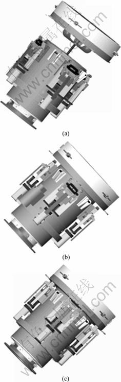
Fig.12 EER manipulating free-flying payload: (a) Capture; (b) Rigidize; (c) Latch
6.2 Zero gravity testbed
EER would work in space station under low weight condition, so zero gravity testbed must be developed to verify the EER function on the ground. There were many solutions to the problem of simulating the functional space environment [15], such as vertical counterweight mechanism, buoyancy tank and air bearing. The counterweight mechanism could provide a constant vertical force to balance the weight of EER, which could realize 3D motion of EER. However, the counterweight mechanism could only afford a small load, increasing the inertia of the system in the vertical direction and reducing the accuracy. In the neutral buoyancy tank, the motion of EER would bring great water drag effect and EER must be specially designed to adapt to underwater condition, which increased the expenditure of EER dramatically. Air bearing offered a nearly friction-free environment in 2D space. With respect to the large mass of EER and the big torque (>800 N?m) provided by the arm joint, universal wheels for air bearings were constituted.
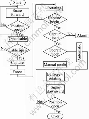
Fig.13 EER control diagram
The zero gravity testbed is shown in Fig.14. The universal wheels could provide X-direction, Y-direction translational freedom and yaw rotational freedom on the floor freely. The Z counterweight in the back could afford Z-direction translational freedom, and pitch counterweight in the middle could supply pitch rotational freedom unrestricted. The bearings in the testbed offered roll rotational freedom finally. All the six-freedom could simulate the movement of GI in space realistically. The EER could operate GI under the control of arm joints. Though a little friction existed in the universal wheels, its influence on the system could be omitted under the large torque of robotic arm joint.
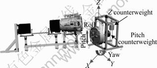
Fig.14 Zero gravity testbed
6.3 Experimental results
EER was developed. Furthermore, experiments were carried out to calibrate its maximum manipulating tolerance. The EER experiments are shown in Fig.15. The maximum manipulating tolerance of EER was gotten, as listed in Table 5. The capture envelope was larger than that of ERA.
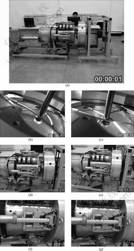
Fig.15 EER experiments: (a) System setup; (b) Capture-1; (c) Capture-2; (d) Rigidize-1; (e) Rigidize-2; (f) Latch-1; (g) Latch-2
Table 5 EER manipulating errors
7 Conclusions
1) Large tolerance capture subsystem has enlarged the capture range of EER greatly. This reduces the accuracy requirements of robotic arms and expands the application scope of EER.
2) Retract and latch subsystems provide up to 16 000 N/4 800 N?m connection force/moment, which guarantees the reliability of large payload operations dramatically.
3) The redundant sensors of EER provide abundant information for the system and ensure the safety of EER itself and payloads.
Acknowledgement
One of the authors, LIU Hong, would express thanks to FENG Fei for his excellent work in the assembly of EER and paper composition.
References
[1] THRONSON H A, AKIN D, GRUNSFELD J, LESTER D. The evolution and promise of robotic in-space servicing [C]// Proceedings of the AIAA SPACE 2009 Conference & Exposition. California, 2009: 1-6.
[2] KITMATCHER G, MAXWELL T G. Further exploration- international space station experience [C]// Proceedings of the SpaceOps 2006 Conference. Rome, 2006: 1-17.
[3] REMBALA R, OWER C. Robotic assembly and maintenance of future space stations based on ISS mission operations experience [J]. Acta Astronautica, 2009, 65: 912-920.
[4] COLESHILL E, OSHINOWO L, REMBALA R, BINA B, REY D, SINDELAR S. Dextre: Improving maintenance operations on the international space station [J]. Acta Astronautica, 2009, 64: 869-874.
[5] NISHIDA S I, YOSHIKAWA T. A new end-effector for on-orbit assembly of a large reflector [C]// Proceedings of the IEEE International Conference on Control, Automation, Robotics and Vision. Singapore: IEEE Press, 2006: 1-6.
[6] REMBALA R, AZIZ S. Increasing the utilization of the ISS mobile service system through ground control [J]. Acta Astronautica, 2007, 61: 691-698.
[7] OGHENEKEVWE V, REDMOND S, HILTZ M, REMBALA R. Human and robotic repair of a solar array wing during ISS assembly mission 10A [J]. Acta Astronautica, 2009, 65: 1717-1722.
[8] KING D, OWER C. Orbital robotics spiral evolution for future exploration missions [C]// Proceedings of the 8th International Symposium on Artificial Intelligence, Robotics and Automation in Space. Munich, 2005: 1-8.
[9] KAWASAKI K. Overview of JEM-EF on ISS [C]// Proceedings of the RIKEN Symposium. Saitama, 2008: 1-3.
[10] FUKAZU Y, HARA N, KANAMIYA Y, SATO D. Reactionless resolved acceleration control with vibration suppression capability for JEMRMS/SFA [C]// Proceedings of the IEEE International Conference on Robotics and Biomimetics. Bangkok: IEEE Press, 2009: 1359-1364.
[11] ACQUATELLA P. Development of automation & Robotics in space exploration [C]// Proceedings of the AIAA SPACE 2009 Conference & Exposition. California, 2009: 1-7
[12] HEEMSKERK C J M, VISSER M, VRANCKEN D. Extending ERA’s capabilities to capture and transport large payloads [C]// Proceedings of the 9th ESA Workshop on Advanced Space Technologies for Robotics and Automation. Noordwijk, 2006: 1-8.
[13] INABA N, ODA M. Autonomous satellite capture by a space robot [C]// Proceedings of the IEEE International Conference on Robotics & Automation. San Francisco: IEEE Press, 2000: 1169-1174.
[14] ZHU Ying-yuan, GAO Xiao-hui, XIE Zong-wu, LIU Hong. Development of a gripper for Chinese space robot [C]// Proceedings of the IEEE International Conference on Mechatronics and Automation. Luoyang: IEEE Press, 2006: 1465-1470.
[15] GAO X H, JIN M H, XIE Z W, JIANG L, NI F L, SHI S C, WEI R, ZHU Y Y, GAO H G, LIU H, BEYER A, KRAEMER E, LANDZETTEL K, SCHOTT J, HIRZINGER G. Development of the Chinese intelligent space robotic system [C]// Proceedings of the IEEE International Conference on Intelligent Robots and Systems. Beijing: IEEE Press, 2006: 994-1001.
(Edited by YANG Bing)
Foundation item: Project(2006AA04Z228) supported by the National High Technology Research and Development Program of China
Received date: 2010-02-22; Accepted date: 2010-09-14
Corresponding author: TAN Yi-song, PhD; Tel: +86-451-86412360; E-mail: yisongtan@163.com

