
Deformation behavior of A6063 tube with initial thickness deviation in free hydraulic bulging
YANG Lian-fa(杨连发)1, 2, GUO Cheng (郭 成)1, DENG Yang(邓 洋)2
1. School of Mechanical Engineering, Xi’an Jiaotong University, Xi’an 710049, China;
2. School of Mechatronic Engineering, Guilin University of Electronic Technology, Guilin 541004, China
Received 28 July 2006; accepted 15 September 2006
Abstract: Experiment on seamless tubes of aluminum alloy A6063 with initial thickness deviation of 0–20% was conducted through a free hydraulic bulging with tube ends free. The influence of initial thickness deviation on the cross-section profile, thickness distribution, maximum internal pressure and maximum radial expansion was investigated. FEM simulation was also performed in order to examine and help explaining the experimental results. The results indicate that the internal pressure and maximum internal pressure appear to be little influenced by the initial thickness deviation, and that the cross-section profile of the bulged tube changes diversely and can not be a perfect circle. The results also suggest that the increase in initial thickness deviation may lead to a remarkable decrease in maximum radial expansion, and a rapid increase in thickness deviation and the center eccentricity of the inner and outer profiles.
Key words: tube; A6063; aluminum alloy; free hydraulic bulging; thickness deviation; FEM simulation
1 Introduction
The mass-reduction in vehicles can be achieved by the application of complex hollow components [1-2], innovated (or modified) processes [3-4] and lightmass materials, so the research on the hydroforming of the aluminum alloy tube becomes a new focus [5-6]. In most research on tube hydro-forming (THF), the tube has been supposed to be uniformity in geometry; however, the non-uniformity in geometry such as thickness deviation and cross-section distortion may exist during the manufacturing or conveying processes of the tube, which has a great impact on the deformation behavior of the tube in THF [7-8]. SHIRAYORI et al [9-10] performed free bulging experimental studies on aluminum alloy tube and copper tube that had an initial thickness deviation of 0-4% along circumferential direction. With the help of FEM simulation and theoretical speculation, SHIRAYORI et al[11] investigated the influence of the initial thickness deviation, strain-hardening exponent n-value and anisotropy coefficient r-value on cross-section profile and wall-thickness distribution of the bulged tube through free hydraulic bulging (FHB) with and without axial push. Nevertheless quite few studies have been done in this aspect and insufficient data are available on the deformation behaviors of tube with geometrical non-uniformity in free hydraulic bulging. In this study, the influence of the initial thickness deviation of 0-20% on the deformation behavior of seamless tubes of aluminum alloy A6063 was investigated through FHB experiment with tube ends free and FEM simulation as well.
2 Fundamental definition
The tubes with initial thickness deviation are supposed as following. The inner and outer profiles of the specimen are perfect circles; however, their centers do not coincide accurately with an initial eccentricity e0 , thereby causing a thickness deviation. The wall- thickness reaches its maximum (tmax) at position “a” (at circumferential angle of 0°) and minimum (tmin) at position “b” (at circumferential angle of 180°), respectively. The magnitudes of the eccentricity and the thickness deviation are defined as the center eccentricity (e) and thickness deviation (τ) in this study, respectively, and are expressed as[10]:
 (1)
(1)
 (2)
(2)
where tmean is the mean wall-thickness, defined as tmean=(tmax+tmin)/2. The initial thickness deviations (τ0) of tubes adopted in the present experiments were 0, 5%, 10%, 15% and 20%, respectively.
In view of the initial thickness of the tube, the cross-section profile during bulging, basically, could not maintain perfect circle, i.e. the radial expansion in the vertical direction  should not be equal to that in the horizontal direction
  and other directions (Fig.1). Therefore, the cross-section distortion (λ) and the mean radial expansion (Δrmean) are introduced in this study and expressed as follows, respectively:
 (3)
(3)
 (4)
(4)
where dmean is the mean diameter of the bulged tube, defined as dmean=(dac+dbd)/2, and d0 denotes the initial outer diameter, i.e. 32 mm in this experiment. λ-value reflects the degree of the profile distortion of the cross-section at the maximum expansion position, or at the axial center of the bulged tube. The larger the λ-value is, the more severe the cross-section distortion appears.
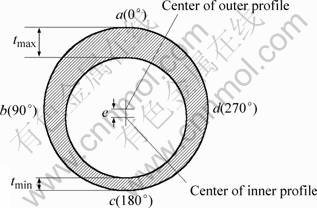
Fig.1 Schematic diagram of cross section of tube with initial wall-thickness deviation
3 Experimental
The tubes used in the present FHB experiments were seamless cold-drawn tubes of aluminum alloy A6063, purchased in market. The tubular specimen was 100 mm in length, 32 mm in outer diameter and 0.75 mm in mean thickness. After the A6063 tubes were cut into required length, they were trimmed and deburred at two ends to secure the required size. The tubes were machined into tubular specimens with initial thickness deviation of 0, 5%, 10%, 15% and 20%, respectively, by means of a wire cut electrical discharge machining (WEDM), and then were annealed for 3 h at 400 ℃. The mechanical properties of the annealed tubes obtained from the uniaxial tension test are shown in Table 1. The experiments were conducted on a self-developed free hydraulic bulging tooling, as shown in Fig.2. This tooling employs internal hydraulic pressure source and requires no complicated and expensive hydraulic pressurization circuit which is usually composed of air-assisted pumps, pressure control valves, flow control valves and associated plumbing, etc. As a stand-alone unit, the tooling can be worked on a conventional single-action press[12]. The experiments were conducted on a universal hydraulic testing machine (600 kN) at the rate of 3-5 mm/min of press ram, and a pressure sensor equipped with the tooling automatically recorded the internal pressure. The expansion zone (l0) was set to be 40 mm in axial length and the two ends of the specimen were allowed to move in axial direction. After the bulging, the diameters dac and dbd at the axial center of the bulged tube were measured by a digit micrometer. Subsequently the measurements of wall-thickness tmax and tmin were performed by a digital micrometer with styluses after sectioning the bulged tubes symmetrically by means of WEDM.
Table 1 Mechanical properties of specimens after annealing
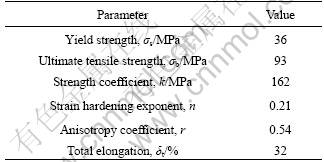
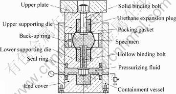
Fig.2 Schematic diagram of experimental set-up for hydraulic bulging
4 FEM simulation
Due to the limitation of experimental approach, FEM simulation of the free hydraulic bulging has been performed by employing a dynamic explicit commercial FE code ‘‘DYNAFORM’’. Fig.3 shows the FE model, where the z-axis denotes the axial direction of the tube. In consideration of symmetric characteristic of the tube deformation, only one-fourth model of the whole geometry consisting of the specimen and the dies was created with the adoption of symmetric constraints applied to the nodes on the two symmetrical planes. The tube in the model originally consisted of 50 camber strips with width of 3.6° in circumferential direction and length of 50 mm in axial direction. Each strip was meshed by shell elements of Tria and Quad types into 100 elements in axial direction and single element in circumferential direction, and consequently the tube was meshed and represented by a total of 5 000 elements and 5 100 nodes. After the thickness data calculated based on the initial thickness deviation in Fig.1 was assigned to each strip, all the strips were integrated into one by the “welding” function in DYNAFORM. In simulation the tubular material was assumed to be isotropic, homogeneous and incompressible in deformation behavior, and described by the power law of σ = kεn. The supporting die was modeled as rigid elements, while the elastic urethane expansion plugs were ignored for quickening the calculation. The coulomb friction was applied between the tube and the supporting die, and the friction coefficient was set at 0.125, which basically accorded with that in the experiment. The loading path (i.e. curve of internal pressure vs time) used in FE simulation was defined as that recorded in experiment, except that the loading speed in the former was higher than that in the latter [12]. In post process after the execution of the simulation, the displacements and thicknesses at nodes a, b, and c of the cross-section at the axial center of the bulged tube were read at each time step for calculating Eqns.(1)-(4).
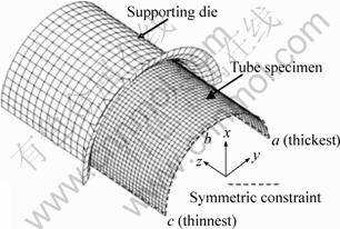
Fig.3 FEM simulation model (1/4) for tube with initial thickness deviation of tube wall
5 Results and discussion
Fig.4 shows the relation between internal pressure and the mean radial expansion at the axial center of the bulged tube, in which the lines and the points denote the results of simulation and experiment, respectively. It is noted that the internal pressure increases rapidly during the initial expansion (approximately Δrmean<1 mm), and then increases slowly until the expansion is complete. The internal pressures for tubes with various initial thickness deviations behave in a similar manner, and their magnitudes seem to be little influenced by the initial thickness deviation. It is observed that the simulation results are very close to the experimental results, as shown in Fig.4; however, the values measured in experiments are consistent above the predicted values. This little inconsistency can be attributed to the unsuitability of the friction model in simulation and the exclusion of the elastic urethane expansion plugs from the FEM model, etc. This implies that the FE model, generally speaking, is reliable and accurate, but on the conservative side.
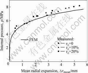
Fig.4 Relation between internal pressure and mean radial expansion
The changes of cross-section distortion with the mean radial expansion are shown in Fig.5. The simulation results agree well with the experimental results. Transformation trend of cross-section distortion prior to Δrmean=1 mm can be easily ascertained through FEM simulation results other than experimental results due to the limitation of experimental approach. Thus, referring to Fig.5, λ-value approximately remains zero during the entire expansion for the normal tube without initial thickness deviation (τ0=0%), i.e. the outer profile of cross-section of the bulged tube holds its initial perfect circle. On the other hand, λ-value for tubes with initial thickness deviation (τ0≠0%) is negative in the former stage of the expansion, i.e. the radial expansion in the horizontal directions is larger than that in the vertical direction  λ-value is quite contrary in the latter stage (except for the case τ0=5%), so there should be the moment that the radial expansions in the two directions are equal, or λ=0 (see Fig.5); however, the cross-section profile is unlikely to be, though very close to, a perfect circle, which is shown in Fig.6.
It can be seen from Fig.5 that the larger the initial thickness deviation is, the earlier λ-value turns into zero. This result may be due to the effect of strain hardening during the bulging deformation. Although the radial expansion at the thinnest position “c” remains the largest in the entire expansion, its strain hardening is the strongest in the former stage of the expansion which in return holds back the further deformation at the position. Moreover, the radial expansion at the thickest position “a” remains the smallest. As a result, the mean radial expansion of position “a” and position “c” is smaller than that at position “b” in the former stage of the expansion. Whereas the situation is on the contrary in the latter stage of the expansion due to the weak strain hardening and the local deformation at the thinnest position “c”.
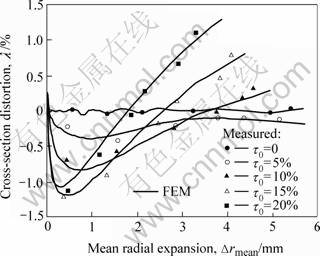
Fig.5 Cross-section distortion at axial center of bulged tube
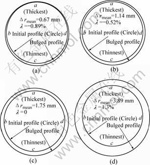
Fig.6 Simulated cross-section at axial center of bulged tube for τ0= 20%
The center eccentricity and the thickness deviation of the cross-section at the axial center of the bulged tube change in a similar way, as shown in Fig.7 and Fig.8, respectively. It can be seen from both the experimental and simulation results that e-value and τ-value increase with the radial expansion increasing, and furthermore, the larger the initial thickness deviation is, the more rapidly the two values increase.
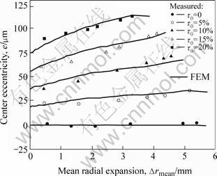
Fig.7 Change of center eccentricity of cross-section at axial center of bulged tube
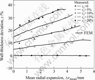
Fig.8 Change of wall-thickness deviation at axial center of bulged tube
Fig.9 shows the maximum internal pressure and the maximum radial expansion when tubes burst. Both experimental and simulation results indicate that an increase in initial thickness deviation leads to a remarkable decrease in maximum radial expansion but a slight decrease in maximum internal pressure. For example, the absolute difference of the maximum internal pressures between case τ0=0 and case τ0=20% is merely 0.7 MPa based on the experiment or 0.6 MPa based on the simulation, and the corresponding relative difference is just 9.43% based on the experiment or 8.07% based on the simulation. However, the absolute difference of the maximum radial expansion is 2.1 mm or 1.8 mm, correspondingly, and the relative difference is 46.53% or 36.33%, correspondingly. The relative differ- ence mentioned above is defined as the outcome of absolute difference divided by the mean value of the two cases.
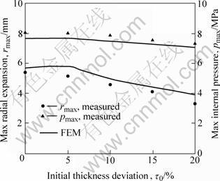
Fig.9 Maximum internal pressure and maximum radial expansion
6 Conclusions
The influence of initial thickness deviation of a tube in FHB on the deformation behavior was studied by means of experiment and FEM simulation. The tube in the present experiment was seamless tube of aluminum alloy A6063 with an initial thickness deviation of 0-20%, and was hydraulically expended with two ends free.
1) The internal pressure (p) increases with the radial expansion (Δrmean) increasing, and appears to be little influenced by the initial thickness deviation (τ0) of a tube.
2) For tubes with initial thickness deviation τ0>5%, cross-section distortion (λ) changes from negative to positive during the bulging, and the profile of the cross-section at the axial center of the bulged tube could not be a perfect circle during the bulging even when λ=0.
3) An increase in initial thickness deviation (τ0) may lead to a remarkable decrease in maximum radial expansion but just a slight decrease in maximum internal pressure.
4) The center eccentricity (e) and the thickness deviation (τ) at the axial center of the bulged tube increase with the radial expansion increasing. The larger the initial thickness deviation is, the more rapidly the two values increase, and the earlier the tube may burst.
References
[1] SCHMOECHEL D, HIELSCHER C, HUBER R. Metal forming of tubes and sheets with liquid and other flexible media [J]. Annals of the CIRP, 1999, 48(2): 497-513.
[2] AHMETOGLU M, ALTAN T. Tube hydroforming: state-of-the-art and future trends [J]. Journal of Materials Processing Technology, 2000, 98: 25-33.
[3] HARJINDER S. Hydroforming simulation becoming cost effective [J]. Forming & Fabricating, 2003, 10(9): 39-46.
[4] MUAMMER K, TAYLAN A. An overall review of the tube hydroform (THF) technology[J]. Journal of Materials Processing Technology, 2001, 108: 384-393.
[5] JOHNSON K I, NGUYEN B N, DAVIES R W, GRANT G J, KHALEE M A. A numerical process control method for circular tube hydroforming prediction [J]. International Journal of Plasticity, 2004, 20: 1111-1137.
[6] MEHDI I, GHATU S, ADAM L. Influence of end-conditions during tube hydroforming of aluminum extrusions [J]. International Journal of Mechanical Sciences, 2004, 46: 1195-1212.
[7] KIUCHI M. Inequality of mechanical and geometrical characteristics of steel pipes and their formability [J]. The Iron and Steel Institute of Japan, 2005, 18(2): 344-347. (in Japanese)
[8] KUMABARA T. Effects of the non-uniformity of steel tubes due to pre-forming history on its free bulging deformation [J]. The Iron and Steel Institute of Japan, 2005, 18(2): 348-351. (in Japanese)
[9] SHIRAYORI A, FUCHIZAWA S, ISHIGURE H, NARAZAKI M. Deformation behavior of tubes with thickness deviation in circumferential direction during hydraulic free bulging [J]. Journal of Materials Processing Technology, 2003, 139: 58-63.
[10] SHIRAYORI A, FUCHIZAWA S, NARAZAKI M. Influence of initial thickness deviation on tube deformation during free hydraulic bulging [J]. Journal of the Japan Society for Technology of Plasticity, 2003, 44(12): 378-381.
[11] SHIRAYORI A, FUCHIZAWA S, NARAZAKI M. Influence of circumferential initial thickness deviation tube deformation in free hydraulic bulging (5th report) [A]. The Proceedings of the 2005 Japanese Spring Conference for the Technology of Plasticity[C]. Sanjyo, Japan: The Japan Society for Technology of Plasticity, 2005: 279-280.
[12] GUO Cheng, YANG Lian-fa. Simple tooling with internal pressure source to evaluate the tube hydro-bulging formability [J]. Chinese Journal of Mechanical Engineering, 2005, 41(9): 180-184. (in Chinese)
(Edited by YUAN Sai-qian)
Foundation item: Project(0135023) supported by the Science Foundation of Guangxi Province, China
Corresponding author: YANG Lian-fa; Tel: +86-773-2951235; E-mail: y-lianfa@163.com

