
Mechanical response of roof rock mass unloading during continuous
mining process in underground mine
HU Jian-hua, LEI Tao, ZHOU Ke-pin, LUO Xian-wei, YANG Nian-ge
Hunan Key Laboratory of Mineral Resources Exploitation and Hazard Control for Deep Metal Mines,
School of Resources and Safety Engineering, Central South University, Changsha 410083, China
Received 10 March 2011; accepted 13 September 2011
Abstract: Taking the test stopes during continuous mining induced roof caving of Tongkeng ore-body No.92 as example, the calculation flow of unloading analysis was established. According to the unloading region division method of the affected zone theory, and the deterioration laws of mechanics parameters of unloading rock mass, the continuous mining process in underground mine was analyzed by the software MIDAS/GTS, the mechanical response of roof rock mass unloading was studied, and the differences were analyzed with the conventional simulation. The result shows that the maximum tensile stress, subsidence displacement and equivalent plastic strain of roof rock mass are 1.5 MPa, 20 cm and 1.5% in the unloading analysis, while 1.0 MPa, 13 cm and 0.9% in the conventional analysis. The values of unloading analysis, which are also closer to the actual situation, are greater than those of conventional analysis; the maximum step in continuous mining is 48 m, which shows that the induced treatment of the roof should be carried out after 2 mining steps
Key words: continuous mining; mining-unload rock mass mechanics; mining-unload disturbance region; dynamic mechanical parameters
1 Introduction
Rock mass excavation engineering can be regarded as an unloading mechanical process because of stress disturbing and stress redistribution of original rock mass stress field by the release of excavation rock mass [1-2]. In general, good mechanical properties of the structure planes of rock mass are still maintained in the loaded mechanical state. But under unloading conditions, particularly when the unloading quantity is large, and tensile stress occurs, rock mass quality deteriorated rapidly, and the rock mass mechanical parameters also decrease sharply. So, as for the mechanical characteristics of rock mass, there are inconsistent with the unloaded and loaded mechanical states [3-7].
Quality deterioration of rock mass caused by unloading mechanical effect have not been taken into account in conventional numerical simulation analysis. That is, the mechanical parameters of rock mass are constant in the whole numerical analysis process, so the damage evolution characteristic of rock mass is difficult to accurately be reflected in mining. Based on the unloading theory, some slopes, tunnels and hydropower were studied by many scholars, and many achievements were obtained. The coupling effects of unloading stress field and fluid field were simulated using FEA by AI [8]. The conceptual unloading geological model was established by XU et al [9], and the genesis mechanism of unloading zone was presented. Under true-triaxial unloading condition, rock dynamical failure process and acoustic emission (AE) characteristics were studied by HE et al [10]. Some concrete example projects such as excavation of dam foundation, tunnel and large-scale underground powerhouse [11-18] were investigated by unloading analysis method. However, there are still two problems which need to be studied. First, the effect of scope under unloading is not clearly defined, and the unloading regions of each steps are not divided either; second, because the variation law of rock mass quality of the specific projects and the unloading quantity are not clear, it can only adopt the mechanical parameters of final unloading step, and it is difficult to reflect the varying law of rock mass deterioration.
According to the unloading rock mass theory, taking the test stopes during continuous mining induced roof caving in the Tongkeng pit No.92 as example, the unloading mechanical effect of roof rock mass was analyzed by numerical simulation method, based on the mechanics parameter deterioration laws of unloading rock mass.
2 Unloading simulation method
Unloading effect is equivalent to a reversed tensile stress which is applied to the rock mass under initial stress [1]. Therefore, it can be seen as a tensile stress applied to the original rock, and its maximum value is σ0+Rt (σ0+Rt is the equivalent tensile strength). So, it can be decomposed into two steps of unloading problem, that is, it is superimposed by stress and strain field of unloading before and after.
The specific calculation process is as follows.
1) The calculation of initial stress field σ0 and displacement field μ0;
2) The calculation of unloading stress field:
 (1)
(1)
where σ?1 and μ?1 are stress field and displacement field and resultant displacement field of ?σ1.
3) Adjustment of rock mass mechanical parameters after unloading;
4) Repeat steps 2 and 3 when the i-th unloading is calculated until non-convergence is met.
 (2)
(2)
where σ?i and μ?i are respectively stress field and displacement field under the N time unloading stress ?σi; σi and μi are respectively the resultant stress field and resultant displacement field of ?σi.
Stress and displacement values of rock mass excavation for each step can be obtained under certain conditions by above multi-step unloading calculation.
3 Division of mining-unload disturbance region
3.1 Theory analysis
Stress is redistributed and secondary stress field is caused by excavation near the rock mass. The region, whose deviation of the secondary stress from initial stress is over a particular value in surrounding rock of excavation disturbed, is defined as effect region, i.e., unloading region.
Mining-unload disturbance region can be described by [19]:
 (3)
(3)
where σinduced is the secondary stress component; σnatural is the initial stress component; λ is the disturbance factor.
Therefore, mining-unload disturbance region can be divided by defining only the unloading region as an effect region whose disturbance factor is over particular value of λ.
3.2 Solution
The theory solution of the secondary stress field and displacement field caused by round and elliptical cavity excavation can be solved under the plane strain condition [19]. The affected region of elliptical cavity is solved by the theory solution, as shown by Eqs. (4), (5) and Fig. 1.
 (4)
(4)
 (5)
(5)
where Wi and Hi must take the maximum value from Eqs. (4) and (5), A=100/2λ, q=W/H, α=1 when k<1, and α=1/k when k>1.
In Fig. 1, pi is the vertical pressure; k is the lateral pressure coefficient; W and H are the minor and long axes of elliptical cavity, respectively; Wi and Hi are the minor and long axes of the affected region elliptical cavity.
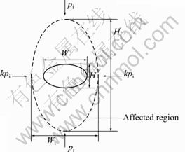
Fig. 1 Unloading graphical solution of oral cavity excavation
4 Numerical models
Some problems existing during mining process, such as pillar recovery, can not be safe and efficient, with great loss of resources, difficulty to control the stope roof, high difficulty and costs to treat goaf, so large-scale ground pressure activities were induced easily. Technology of continuous mining-induced caving roof is presented to these problems [20-21], and its essence is a process of roof continuous unloading.
Using the construction stage function of MIDAS/ GTS FEA software, the previous step results of stress, strain and displacement are introduced into next step analysis. So, mechanical parameters of unloading rock mass deterioration can be dynamicaclly adjusted in the unloading analysis, that is, the mechanical response analysis of real unloading process can be achieved.
By comparing with the difference of conventional analysis, numerical simulation programs of continuous mining can be analyzed in two cases. Case 1 is the convention analysis, while case 2 is the analysis based on unloading theory. Basic models and initial material parameters of two cases do not have any difference, but in model of case 2, unloading regions have been fixed in advance, and deterioration mechanical parameters would be used in unloading regions.
4.1 Model construction
The simplified models shown in Fig. 2 are established according to test stopes during continuous mining induced roof caving of Tongkeng ore-body No.92. The model obeys the following assumptions:
1) Model dimensions are 250 m×500 m;
2) The hanging wall is the lentil limestone, the dip angle of orebody is 15°, the thickness is 40 m and the footwall is wide bands limestone.
3) The average height of surface is taken as the initial height to deadweight loading; therefore, the model top is level.
The horizontal displacement of lateral boundaries of calculation model is restricted, the bottom is fixed, and the surface is a free boundary. The material model is the elastic-plastic constitutive model. Mohr-Coulomb strength criterion is used to determine the failure of rock mass. The vertical ground stress is added through deadweight of rock mass. The lateral pressure coefficient is 2.8, and the lateral stress is automatically calculated by the lateral stress coefficient method of software.
FE models of the two cases are shown in Fig. 2, where case 1 is conventional analysis model and case 2 is unloading analysis model. The initial mechanical parameters of rock mass are shown in Table 1.
4.2 Division of unloading region
When unloading regions are divided, circumscribed ellipse of section can be solved, then the affected zone of ellipse cavity is taken as the unloading region under the condition that the excavation section is parallelogram. The affected zone whose disturbance factor (λ) is 10% is determined as the unloading region [22-23], and the unloading region is shown in Fig. 3.
From Fig. 3, the unloading region increases with the increase of mining steps and the expansion of the excavation scope. And the former unloading region is always within latter scope, which indicates that rock mass in some area is unloaded a number of times, and its mechanical parameters also deteriorate several times.

Fig. 2 Numerical calculation model: (a) Geometry model; (b) Case1; (c) Case 2
Table 1 Physical and mechanical parameters of initial ore rock
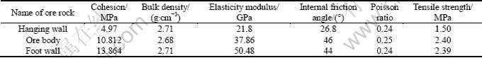
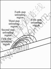
Fig. 3 Division of unloading region
4.3 Deterioration laws of rock mass mechanical parameters in excavation unloading process
By unloading theory, deterioration laws of mechanical parameters rock mass were obtained in excavation unloading process by the method carrying out 6 steps of continuous unloading calculations and in each step unloading quantity of 10% of the initial stress [24]. And the functions of unloading rock mass mechanical parameters such as internal friction angle, cohesion, elasticity moduli, Poisson ratio and the unloading percentage are fitted by polynomial fitting method, the fitting formulas are shown as follows

 (6)
(6)

 (7)
(7)

 (8)
(8)

 (9)
(9)
where ηφ, ηc, ηE and ημ are the values of the internal friction angle, cohesion, elasticity moduli and Poisson ratio respectively; α is the unloading percentage.
5 Calculation results and anaysis
5.1 Initial stress field
Initial stress state is the result of action by ground stress without artificial disturbance. It relates significantly to whether the numerical simulation could reflect the actual situation or not. These two cases have the same initial ground stress condition which produces uniform variation along the height direction (Fig. 4). And stress has changed near the formation surfaces, and its tendency is consistent with that of the stress of tilt ore body. It ensures the validity of comparison of data in simulation.
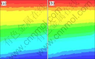
Fig. 4 Initial ground stress: (a) Case 1; (b) Case 2
5.2 Analysis of stress
The yield damage of rock mass is caused by the effect of secondary stress field in underground engineering. With increasing the mining steps, the area of exposure expands, and the roof is the main area coming out damage due to no left pillars in continuous mining. Because rock mass is brittle, and its tensile strength is far smaller than the compressive strength, the main damage modes are tensile failure and shear failure of the roof rock mass. So, the emergence area and variation law of the tensile stress should be focused in numerical analysis.
From Fig. 5 and distributional characteristics of tensile area, some results can be obtained.
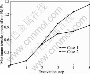
Fig. 5 Variation curve of roof tensile stress
1) At the beginning, due to the artificial disturbances, excavation rock is non-unloading rock. The tensile area is small, and the tensile stress is also small, only 0.1 MPa. The tensile area distributes in the sides of excavation area due to the effect of excavation shapes and sizes.
2) After excavation, stress concentration is found in corner rock mass of excavation area, and the stress concentration is significant in the lower left corner especially. So, to ensure the safety of corner rock mass, certain security measurements should be taken.
3) The distribution area scope and value of tensile stress increase gradually with the increase of the excavation steps, and the increase speed of case 2 is faster than that of case 1. The reason is that the deterioration of rock mass caused by excavation unloading is considered in case 2 but not in case1.
4) The variation of tensile stress is sharper than other steps in step 2 and step 3. It indicates that there is a large possibility of mergence to roof damage, which should be highlighted.
5) The maximum roof tensile stress is more than 1 MPa in step 3, and about 1.3 MPa in step 4. From Fig. 1, the tensile strength is 1.5 MPa, therefore, the goaf emerged in step 1 and step 2 should be operated by induced caving technology after step 3 to ensure the safety of engineering. That is, the maximum step is 48 m.
5.3 Analysis of displacement
The roof displacement increases gradually with the advance of the mining steps and enlargement of goaf area. The maximum displacements of two cases merge in step 5, which corresponds with the actual situation.
From Fig. 6, the displacement and slope of displacement curve in case 2 are obviously larger than those in case 1. The reason is that the deterioration of rock mass caused by excavation unloading is considered in case 2 but not in case 1. Meanwhile, the interaction between the deterioration of rock mass and variation of displacement is also an important factor. On one hand, the deterioration of rock mass develops with the variation of roof displacement; on the other hand, roof displacement would bring about a greater change due to the deterioration of rock mass.
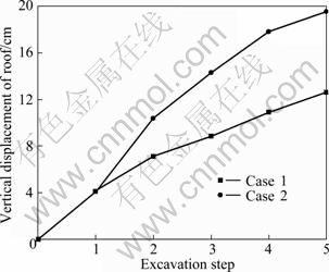
Fig. 6 Displacement curves of roof
5.4 Analysis of plastic zone
The scope of plastic zone expands with the advance of excavation steps. From Fig. 7, the plastic zone is arcuation, and mainly distributes in roof. The height of plastic zone arch of case 2 is 20% larger than that of case 1. It indicates that plastic zone of case 2 is larger, and the effect on the roof overlying strata is also more significant, which facilitates induction caving of roof.
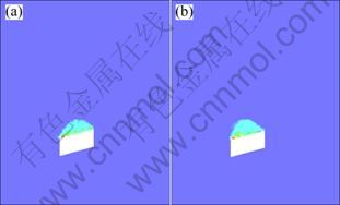
Fig. 7 Plastic zone distribution of step 5: (a) Case 1; (b) Case 2
Figure 8 shows the curves of equivalent plastic strain. From Fig. 8, equivalent plastic strain increases with the advance of excavation steps; the maximum variation rate emerges in step 2 and step 3, and inflection point comes in step 3. The speed of equivalent plastic strain of case 2 is larger than that of case 1, therefore, rock mass quality of case 1 deteriorates faster than that of case 2.
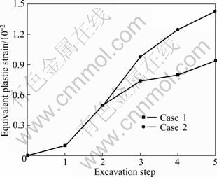
Fig. 8 Curves of equivalent plastic strain
6 Conclusions
1) The specific simulation process of mining-unload excavation was established according to rock mechanics theory. Mining-unload disturbance region was divided based on the affected region theory.
2) Based on the continuous mining-induced caving roof case of the No.92 ore body in Tongkeng mine, the dynamic mechanical parameters reflecting the deterioration rule of unloading rock mass were used, and the numerical model of unloading analysis was established.
3) Underground continuous mining process was simulated by unloading and conventional methods in the No.92 ore body in Tongkeng mine, meanwhile, the results obtained were compared. From the results, the values of tensile stress, displacement and equivalent plastic strain of unloading analysis are greater than those of conventional analysis, and are also closer to the actual situation.
4) The maximum step in continuous mining is 48 m from simulation results; it shows that the induction of the roof should be carried out after 2 mining steps.
References
[1] LI Jian-lin. Unloading rock mass mechanics [M]. Beijing: China Water Power Press, 2003. (in Chinese)
[2] LIU Chang-wu, ZHAI Cai-wang. Spatial strata stress field evolution regularity induced by mining engineering and simulation [M]. Zhengzhou: Yellow River Conservancy Press, 2005. (in Chinese)
[3] ZHOU Xiao-ping, HA Qiu-ling, ZHANG Yong-xing, WANG Jian-hua,, ZHU Ke-shan. Analysis of localization of deformation and complete stress-strain relation for mesoscopic heterogenous brittle rock materials when axial stress isheld constant while lateral confinement is reduced [J]. Chinese Journal of Rock Mechanics and Engineering, 2005, 24(18): 3236-3245. (in Chinese)
[4] ZHAO Er-ping. Study of unloading rock mass yield criterion and engineering application [D]. Yichang: China Three Gorges University, 2008. (in Chinese)
[5] PEI Jian- liang, LIU Jian- feng, XU Jin. Experimental study of mechanical properties of layered marble under unloading condition [J]. Chinese Journal of Rock Mechanics and Engineering, 2009, 28(12): 2496 -2502. (in Chinese)
[6] ZHOU Hua, WANG Guo-jin, FU Shao-jun, ZOU Li-chun, CHEN Sheng-hong. Finite element analysis of foundation unloading and relaxation effects of xiaowan arch dam [J]. Rock and Soil Mechanics, 2009, 30(4): 1175-1180. (in Chinese)
[7] LI Dong-hai, LIU Jun, NIU Xiao-kai, JIN Zhen-ming, ZHAO Zhi-tao. Research on vertical deformation of down shotcrete tunnel during unloading of pit excavation [J]. Rock and Soil Mechanics, 2009, 30(2): 563- 571. (in Chinese)
[8] AI Wan-min. Experimental study and numerical analysis of coupling between seepage field and stress field of rock mass with unloading [D]. Chongqing: Chongqing University, 2005. (in Chinese)
[9] XU Wei-ya, XIE Shou-yi, XU Rui-chun, LIU Shi-jun, ZHU Zen-de. Study on characteristics and numerical simulation for slope unloading zonein shuibuya hydropower project dam site area [J]. Journal of University of Hydraulic and Electric Engineering (Yichang), 2002, 24(2): 101-106. (in Chinese)
[10] HE M C, MIAO J L, FENG J L. Rock burst process of limestone and its acoustic emission characteristics under true-triaxial unloading conditions [J]. International Journal of Rock Mechanics & Mining Sciences, 2010, 47(2): 286-298.
[11] DONG Zhi-hong, DING Xiu-li, LU Bo, ZHANG Feng, ZHANG Lian. Displacement back analysis of rock mechanical parameters of large-scale underground powerhouse with unloading surrouding rockmass [J]. Rock and Soil Mechanics, 2008, 29(6): 1562-1568. (in Chinese)
[12] LENG Xian-lun, SHENG Qian, ZHU Ze-qi, ZHANG Yong-hui. Study on excavation disturbed zone in surrounding rock of tunnel with various tbm driving rates [J]. Chinese Journal of Rock Mechanics and Engineering, 2009, 28(S2): 3692-3698. (in Chinese)
[13] HUANG Sheng-wen, SI Tie-han, FENG Jian-wei, CAO Yun-qiang. Analysis of surrounding rock pressure of niuhushan tunnel under unloading effect [J]. Chinese Journal of Underground Space and Engineering, 2009, 5(1): 79 -84. (in Chinese)
[14] MAKURAT A, AHOLA M, KHAIR K. Decovakex test-case one [J]. International Journal of Rock Mechanics and Mining Sciences, 1995, 32(5): 399-408.
[15] HUANG T H, CHANG C S, CHAO C Y. Experimental and mathematical modeling for fracture of rock joint with regular asperities [J]. Engineering Fracture Mechanics, 2002, 69(17): 1977-1996.
[16] JING L, NORDLUND E, STEPHANSSON O. A 3D constitutive model for rock joints with anisotropic friction and stress dependency in shear stiffness [J]. International Journal of Rock Mechanics and Mining Sciences, 1994, 31(2): 173-178.
[17] BOULON M, ARMAND G, HOTEIT N. Experimental investigations and modeling of shearing of calcite healed discontinuities of grandiosity under typical stresses [J]. Engineering Geology, 2002, 64(2-3): 117-133.
[18] SOULEY M, HOMAND F, AMADEI B. An extension to the Saeb and Amadei constitutive model for rock joints to include cyclic loading paths [J]. International Journal of Rock Mechanics and Mining Sciences & Geomechanics Abstracts, 1995, 32(2): 101-109.
[19] HUDSON J A, HARRISON J P. Engineering rock mechanics: An introduction to the principles [M]. London: Elsevier, 2009.
[20] HU Jian-hua, ZHOU Ke-ping, LI Xi-bing. Numerical analysis of application for induction caving roof [J]. Journal of Central South University of Technology, 2005, 12(S1): 146-149.
[21] HU Jian-hua, ZHOU Ke-ping, LUO Xian-wei, DENG Hong-wei. Panoramic inspection and evaluation of blasting effect of induction caving roof [J]. Rock and Soil Mechanics, 2010, 31(5): 1529- 1533. (in Chinese)
[22] ZHU Ji-liang. Geology-mechanics responses and evaluation of large-scale high rock slope excavation―Taking the xiaowan hydroelectric station high slope as a case [D]. Chengdu: Chengdu University of Technology, 2006. (in Chinese)
[23] ZHOU Huo-ming, SHENG Qian, LI Wei-shu, XIAO Guo-qiang. Excavation-disturbed zone and weaken degree of mechanical properties for rockmass of tgp shiplock slope [J]. Chinese Journal of Rock Mechanics and Engineering, 2004, 23(7): 1078-1081. (in Chinese)
[24] LEI Tao. Dynamic response simulation of induced caving roof with continuous mining under mining unloading [D]. Changsha: Central South University, 2010. (in Chinese)
地下连续采矿过程中顶板岩体卸荷的力学响应
胡建华, 雷 涛, 周科平, 罗先伟, 杨念哥
中南大学 湖南省深部金属矿开发与灾害控制重点实验室 资源与安全工程学院, 长沙 410083
摘 要: 以铜坑矿92#矿体连续采矿顶板诱导崩落采场为研究对象,建立模拟的卸荷计算流程。依据影响区域理论的卸荷带划分方法,基于开挖卸荷过程中岩体力学参数变化规律,利用有限元软件MIDAS/GTS对地下连续采矿过程进行卸荷分析,并与常规分析进行对比。结果表明:卸荷分析的顶板最大拉应力、下沉位移以及等效塑性应变分别达到1.5 MPa、20 cm和1.5%;常规分析的顶板最大拉应力、下沉位移以及等效塑性应变分别为1.0 MPa,13 cm和0.9%;卸荷分析值均比常规分析值大,更接近实际情况;连续采矿开采的最大步距为48 m,在开采两步距以后,应当对顶板进行诱导处理。
关键词: 连续采矿;卸荷岩体力学;卸荷带;动态力学参数
(Edited by YANG Hua)
Foundation item: Projects (50934006, 51074178) supported by the National Natural Science Foundation of China; Project (2010QZZD001) supported by the Fundamental Research Funds for the Central Universities of China
Corresponding author: LEI Tao; Tel/Fax: +86-731-88879965; E-mail: Leitao539@163.com
DOI: 10.1016/S1003-6326(11)61116-3

