Analytical model of shear mechanical behaviour of bolted rock joints considering influence of normal stress on bolt guide rail effect
来源期刊:中南大学学报(英文版)2021年第5期
论文作者:王亮清 郑罗斌 朱林锋
文章页码:1505 - 1518
Key words:bolted rock joints; shear test; shear behaviour; analysis model
Abstract: Rock bolts have been widely used in slopes as a reinforcement measure. Modelling the shear mechanical behaviours of bolted rock joints is very complicated due to the complex factors that affect the axial force and shear force on the bolts. Rock bolts under shear action exhibit the guide rail effect; that is, the rock mass slides along the rock bolt as if the rock bolt is a rail. The normal stress can inhibit the guide rail effect and reduce the axial force on bolts. However, this factor is not considered by the existing analysis models. Shear tests of bolted joints under different normal stresses were carried out in the laboratory. During the test, the axial force on each point monitored on the bolt was recorded by a strain gauge, and the attenuation trend of the strain was studied. An analytical model that considers the inhibition of the bolt rail effect due to an increase in the normal stress was proposed to predict the shear mechanical behaviour of rock bolted joints. The new model accommodates the bolt shear behaviours in the elastic stage and plastic stage, and the estimated values agree well with the results of the direct shear tests in the laboratory. The validation shows that the proposed model can effectively describe the deformation characteristics of the bolts in the shear tests.
Cite this article as: ZHENG Luo-bin, WANG Liang-qing, ZHU Lin-feng. Analytical model of shear mechanical behaviour of bolted rock joints considering influence of normal stress on bolt guide rail effect [J]. Journal of Central South University, 2021, 28(5): 1505-1518. DOI: https://doi.org/10.1007/s11771-021-4700-3.

J. Cent. South Univ. (2021) 28: 1505-1518
DOI: https://doi.org/10.1007/s11771-021-4700-3

ZHENG Luo-bin(郑罗斌), WANG Liang-qing(王亮清), ZHU Lin-feng(朱林锋)
Faculty of Engineering, China University of Geosciences, Wuhan 430074, China
 Central South University Press and Springer-Verlag GmbH Germany, part of Springer Nature 2021
Abstract: Rock bolts have been widely used in slopes as a reinforcement measure. Modelling the shear mechanical behaviours of bolted rock joints is very complicated due to the complex factors that affect the axial force and shear force on the bolts. Rock bolts under shear action exhibit the guide rail effect; that is, the rock mass slides along the rock bolt as if the rock bolt is a rail. The normal stress can inhibit the guide rail effect and reduce the axial force on bolts. However, this factor is not considered by the existing analysis models. Shear tests of bolted joints under different normal stresses were carried out in the laboratory. During the test, the axial force on each point monitored on the bolt was recorded by a strain gauge, and the attenuation trend of the strain was studied. An analytical model that considers the inhibition of the bolt rail effect due to an increase in the normal stress was proposed to predict the shear mechanical behaviour of rock bolted joints. The new model accommodates the bolt shear behaviours in the elastic stage and plastic stage, and the estimated values agree well with the results of the direct shear tests in the laboratory. The validation shows that the proposed model can effectively describe the deformation characteristics of the bolts in the shear tests.
Key words: bolted rock joints; shear test; shear behaviour; analysis model
Cite this article as: ZHENG Luo-bin, WANG Liang-qing, ZHU Lin-feng. Analytical model of shear mechanical behaviour of bolted rock joints considering influence of normal stress on bolt guide rail effect [J]. Journal of Central South University, 2021, 28(5): 1505-1518. DOI: https://doi.org/10.1007/s11771-021-4700-3.
1 Introduction
Rock bolts are widely used in rock excavation to strengthen fractured rock masses and reduce the deformation of rock slopes. In the past, fully grouted bolts were usually described as pure tensile elements supporting unstable rock masses, and the mechanism of the bolts and their performance under the action of pull-out were thoroughly studied [1-5]. However, on-site monitoring results show that a large number of engineering bolts have suffered shear failure. To address this issue, some studies have been performed on the anchoring mechanism of bolts under the shear action of bolted rock joints [6-9].
The reinforcement mechanism of bolted joints can be very complex, as the axial force and shear force of the bolt are affected by many factors, such as the properties and geometric mechanical parameters of the steel bar [10-12], the mechanical properties of the rock and the properties of the joint surface [13-17]. Researchers have conducted experimental and theoretical studies on the shear mechanical behaviour of bolted joints. LI et al [18] performed a direct shear test with different bolting angles and pointed out that as the angle of the bolt increases, the contribution of the bolts increases first and then decreases. LIU et al [19] found that the inclination of the bolt has a significant impact on the shear strength and shear deformation, and a larger inclination angle is conducive to exerting the dowel shear force of the bolt. SPANG et al [20] concluded that inclined bolts can increase the shear strength to 90% of the ultimate tensile load. LUDVID et al [21] analyzed the influence of the bolt diameter on the shear strength and found that bolts with larger diameters have higher shear strength. CUI et al [22] conducted direct shear tests under the conditions of constant normal load (CNL) and constant normal stiffness (CNS) and compared the results of the two types of tests. A bolted rock mass has a higher shear strength and lower normal displacement and friction coefficient under the condition of CNS. WU et al [23] investigated the effect of cyclic shear load on the shear performance of bolted joints. The results indicate that the shear strength reduction of bolted joints under the cyclic loading condition was more significant compared to the un-bolted joints. YOSHINAKA et al [24], HASS [25] previously proposed that the normal stress of the joint surface has a small weakening effect on the shear strength of bolted rock joints, but the normal stress factor has been ignored by many researchers. SONG [26] investigated the shear action mechanism of rock bolts and found that bolts not only play the role of transverse reinforcement but also act as a “guide rail”, especially under high normal stress conditions, which weakens the shear strength of the rock mass. Subsequently, some investigations provided further evidence for this phenomenon [27, 28].
Based on the understanding of the factors influencing the shear characteristics of bolted joints, many researchers have used theoretical analysis to establish models for calculating the shear strength of bolted joints. KAWAKATA et al [29] proposed an analytical model considering the axial pull-out load, which simplifies the global shear force on bolted rock joints into the dowel shear force but does not consider the global shear force provided by the axial force. FERRERO [30] proposed a model that takes into account the axial force generated by shear motion and the dowel shear force exerted by transverse action. However, the installation angle of the bolt and the bond strength of the mortar-bolt interface are not considered. LI et al [31] proposed a model capable of estimating the ultimate shear strength of the double shear test, but this model fails to predict the complete shear load-shear displacement curve. PELLET et al [32] considered the tensile deformation, shear deformation and local rotation of the bolt near the joint surface and concluded that the shear resistance of the bolt comprises the joint action of the bolt axial force and dowel shear force. ZHAO et al [33] proposed a mechanical model of composite soft rock with a weak interface and a rock bolt that takes into account the transverse shear sliding evolution of the dowel shear force on the bolt without considering the axial force on the bolt. MA et al [34] used a trilinear bond-slip model to describe the bond stress between the grout and the bolt interface, considered the prestress of the bolt, and proposed an analytical model for rock joints reinforced by fully grouted rock bolts. CHEN et al [35] proposed a new analytical model to predict the mechanical behavior of anchor joints under the combined action of the pull load and shear load and considered the axial behavior of bolts based on the real three-wire bonding slip model.
Researchers have proposed analytical models to describe the mechanical behaviour of bolted rock joints. However, few are able to predict the complete shear load-shear displacement curve, and all ignore the effect of the normal load on the shear behaviour of bolted rock joints. During the shearing process of bolted rock joints, the rock mass will slide along the bolt as if the bolt is a rail, which is called the bolt guide rail effect. The normal load will inhibit the guide rail effect and affect the deformation of the bolt. Thus, direct shear tests were carried out, and the attenuation trend in the axial strain at the end of the rock bolt head was obtained with increasing normal stress, and the function describing the attenuation trend was fitted by MATLAB software. Additionally, the theoretical formulas for the shear force and the axial force at the intersection of the bolt and the joint were deduced, taking into account the attenuation trend of the bolt axial force with the normal stress. The proposed model was verified by the experimental results, indicating that the model can effectively describe the deformation characteristics of bolts under shear action. Finally, the discussion section in the article presents the influence of the pretension load on the shear behaviours of bolted rock joints.
2 Experimental
2.1 Experimental principles and test instrument
The principles of the designed test model are shown in Figure 1. We aim to investigate the effect of the normal load on the shear mechanical behaviour of fully grouted bolts using sandstone from Yichang, Hubei Province, China, as the test material. The direct shearing instrument uses a TAWJ-100 automatic control rock joint shearing instrument developed by China University of Geosciences (Wuhan) and Changchun Chaoyang Test Instrument Co., Ltd. The maximum load of the test instrument in the vertical and horizontal directions is 100 kN. The minimum and maximum loading rates are 0.1 and 10 kN/s, respectively. The minimum and maximum displacement loading speeds (displacement control) are 0.01 and 20 mm/min, respectively. Two lateral displacement sensors are used to record the shear displacement, and four normal displacement sensors are used to record the normal displacement.

Figure 1 Principles of shear test of bolted joints
All direct shear tests are carried out according to the newly revised International Society for Rock Mechanics (ISRM) recommended method [36]. We perform shear tests on unbolted rock joints and bolted rock joints under 4 levels of normal stress. The normal stresses are 0.5, 1.0, 1.5 and 2.0 MPa, and the corresponding stress range is approximately 20 to 100 m in vertical crustal stress depth. After the specimen is installed in place, the horizontal jack is pushed forward at a constant speed of 0.5 mm/min to apply shear force. We end the tests when the shear strength is stable or the shear displacement reaches approximately 10% of the length of the specimen.
2.2 Sample preparation
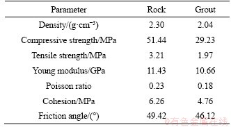
The basic physical properties of the rock and mortar are determined through routine mechanical tests (see Table 1). According to the test instrument and test requirements, the dimensions of the processed rock sample are 150 mm×150 mm×150 mm. The guide rail effect is similar to the dilatancy effect. To avoid confusion with the dilatancy behaviour caused by the rough joint surface, a flat and smooth joint surface is used in this paper. The preparation process of the bolted joint specimens is shown in Figure 2. Bolt holes with a diameter of 12 mm are machined on the vertical structure surface, and prestressed nut mounting grooves are drilled in the centre of the upper and lower discs. The shape of the mounting groove is cylindrical, with a diameter of 30 mm and a height of 30 mm. After the bolt hole is filled with grout, we install nuts for pre-tightening, and place the sample in a constant temperature and humidity curing box for 28 d. The bolts are 304 plain steel bars that are processed into dimensions of d8 mm×140 mm. The mechanical properties of the bolts are listed in Table 2. A high-sensitivity resistance strain gauge adhered to the bolt is used to measure the axial strain values at various positions on the bolts. Each bolt is bonded with 7 strain gauges, which are pasted at intervals of 10 mm. The specific layout position is shown in Figure 1. According to the industry-recommended strain gauge connection and protection method, 502 glue is used to adhere the gauge, which is then coated with 703 white silicone rubber, preventing the failure of the strain gauge due to moisture.
Table 1 Physical parameters of rock mass
2.3 Test results
Figure 3 shows the shear load-shear displacement curves of unbolted rock joints and bolted rock joints under the condition of 4 levels of normal loads. As shown in Figure 3(b), the shear load-shear displacement curves of the bolted rock joints can be divided into three stages: the initial elastic stage, the elastoplastic stage, and the plastic hardening stage. Take the curve of the normal stress of 2.0 MPa as an example. The OA section is in the elastic stage; the shear load increases rapidly with increasing shear displacement, and the two have an approximately linear relationship. The AB section is the elastoplastic stage; the shear load increases with increasing shear displacement, and the slope of the curve gradually decreases. The BC section is the plastic hardening stage; the shear load increases slowly, and the slope of the curve is small.
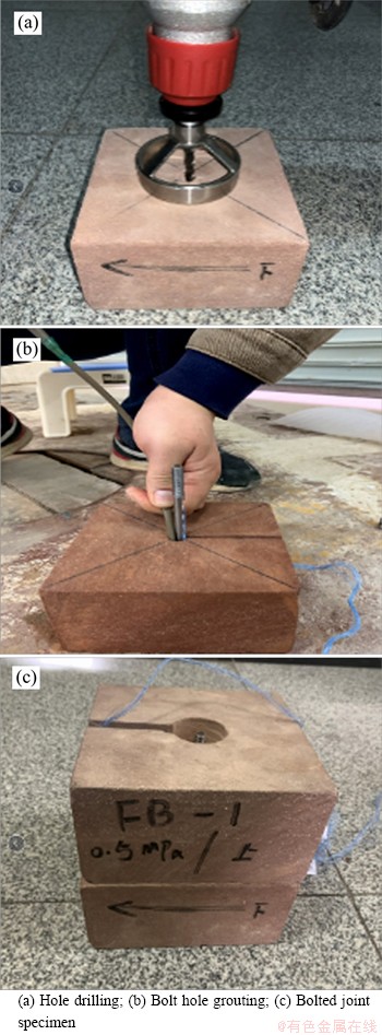
Figure 2 Preparation process of bolted joint specimens:
Table 2 Bolt physical parameters


Figure 3 Shear displacement-shear stress curve:
3 Effect of normal stress
3.1 Rock bolt bending deformation
The bolt deformation after the shear test is shown in Figure 4. At this time, the rock bolt is in the plastic stage. The bolts have undergone bending deformation near the joint, and the shape is similar to that of an S. The bending angle α of the bolt increases with increasing normal stress, and the axial deformation length of the bolt decreases with increasing normal stress. This shows that a high normal stress is conducive to the development of the dowel shear force but not conducive to the development of the axial force. The relationship between the bending angle α and the normal stress is shown in Figure 5. The results indicate that the bending angle increases almost linearly as the normal load increases.
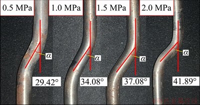
Figure 4 Bending angle α
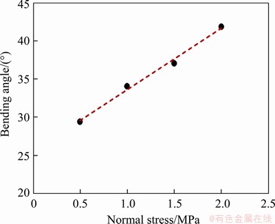
Figure 5 Relationship between bolt bending angle and normal stress
3.2 Axial deformation of bolts
We use the strain gauges to monitor the strain of the bolts. Figure 6 shows the relationship between the strain measured by the strain gauge and the shear displacement. A positive strain indicates tensile strain, and a negative strain indicates compressive strain. Due to the strain gauge range, only the strain up to a shear displacement of 5 mm is recorded. Figure 6 shows that the axial strain in the bolt increases with increasing shear displacement, indicating that the axial force on the bolt increases with increasing shear displacement. For the curves exhibiting larger strains, the deformation increases linearly when the displacement is small. When the displacement exceeds a critical point, the deformation increases rapidly in a parabolic manner. Figure 7 shows the curve of strain gauge 1 under different normal stresses. When the normal stress increases, the axial strain curve decreases.
We combine the results from Sections 3.1 and 3.2 and conclude that as the normal stress increases, the bending angle increases with decreasing axial strain, which results in a smaller axial force on the bolt. Here, we analyze the cause of this phenomenon. During the shearing process, the rock mass will slide along the deformed bolt due to the existence of the bolt. The bolt acts like a rail, which is called the bolt guide rail effect. When the rock slips along the bolt, the joint surface will tend to open, and the bolt will be stretched under tensile force. As the normal stress increases, the rail effect will weaken, and the normal displacement of the rock will be limited, which will cause the axial tension on the bolt to decrease, and the axial force on the bolt will play a smaller role. Therefore, the guide rail effect should be taken into account in the analysis of bolt shear behaviour and in the prediction of the shear strength of bolted rock joints.

Figure 6 Relationship between bolt strain and shear displacement:
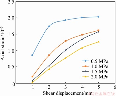
Figure 7 Strain gauge 1 under different normal stresses
4 Analysis of bolted rock joint shear mechanics
The bolts are usually considered straight bars, and the axial forces are analyzed according to the static equilibrium equation. In fact, the bolts are subjected to shear action, and the bending angle increases continuously with the shear displacement. Therefore, it is necessary to analyze the axial force on the bolt as a continuous bending member. In addition, due to the bolt guide rail effect, the axial strain in the bolt is not only related to the shear displacement but also decreases with increasing normal stress. Therefore, the two aforementioned factors need to be fully considered.
4.1 Shear mechanics model
The bolt reinforces a jointed rock mass by strengthening the shear capacity of the joint, restraining the deformation of the rock mass, and improving the stability. The anchorage effect is mainly manifested in three aspects. First, the axial force actively provided by the bolt is directly loaded on the joint to enhance the shear strength of the joint. Second, the bolt itself is a rigid body with high strength. When subjected to a lateral load, the bolt itself limits the deformation of the joint, namely, the dowel shear effect. Third, the axial deformation of the bolt bending, the component of the axial force along the joint surface, directly provides an anti-sliding force. Studies show that under the action of lateral shear, the bolt undergoes obvious bending deformation in the range of 2-4 times the diameter of the bolt near the joint. The transverse deformation of the bolt leads to mutual extrusion with the grout, resulting in the grout breaking, and decoupling of the grout and the bolt occurs near the joint, as shown in Figure 8.A simplified mechanical model of the bolt under shear action is shown in Figure 9. During the shearing process, two singular points are formed on the bolt: the intersection of the bolt and the joint surface (point O), where the bending moment of this point is zero, and at point A, where the shear force is zero and the bending moment reaches the maximum. In addition, point B is the starting point of the bend, where the deflection is zero. At point C, there is no relative displacement between the bolt and the host concrete, as the bolted end is fixed by the plates. Hence, the interfacial shear stress at point C is equal to zero, and τs is the bond stress at the bolt-grout interface. There is no bond stress in the OB section due to the decoupling of the grout from the bolt. Because of the short bond section and low bond strength between the bolt and the grout in the test, its influence is ignored in the following division. MA et al [34] and PELLET et al [32] divided the bolt into three sections, OA, AB and BC, and considered the length of the AB segment to be approximately equal to that of OA, i.e., LOA=LAB=LA. The axial and shear forces at point O are NO and QO, respectively, and the acting force of the grout on the bolt is Pu.
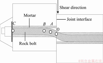
Figure 8 Deformation of bolt under shear action
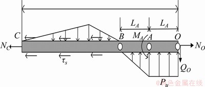
Figure 9 Diagram of bolt forces
4.2 Axial load on bolt
The bolt begins to bend and deform under shear action. The bolt is divided into left and right parts along section n-n at point B by the cross-section method. As shown in Figure 10, the CB segment is the left section, and NC is the axial force at point C. The BO section is the right section, point O is the intersection of the QO and QB extension lines, and the included angle is equal to the rotation angle ωo of point O. The uniformly distributed load Pu is equivalent to the concentrated load Qs. The shape of the distribution of Pu in the BO section is approximately a rectangular trapezoid, and the length of the upper base of the trapezoid is half the length of the lower base. According to the trapezoidal centroid calculation method, the position of the concentrated load Qs is 7/18 the length of the BO section (near point O). For the convenience of calculation, it is approximated that the direction of Qs passes through point OO. Because the shear force at point A is zero, the relationship between Pu and QO can be calculated by establishing the following equation:
 (1)
(1)
and the magnitude of the concentrated load Qs can be expressed as:
 (2)
(2)
We project the internal and external forces on the BO rod to the normal direction of section n-n and calculate the axial force at point B according to the static balance equation:
 (3)
(3)
 (4)
(4)
Substituting Eq. (3) into Eq. (4) yields:
 (5)
(5)
In the elastic stage, according to Hooke’s law, the axial force NC can be expressed as:
 (6)
(6)
where A is the cross-sectional area of the bolt; E is elastic modulus of the bolt; εC is a function of the shear displacement, which can be expressed as [37]:
 (7)
(7)
where S is the shear displacement; a and b are the experimental parameters, in which the values are determined according to tests in Ref. [37].
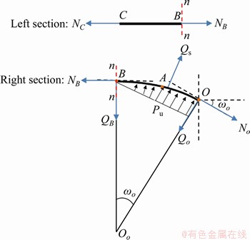
Figure 10 Point B section method
Since the normal stress suppresses the rail effect, the axial strain in the bolt is reduced. Therefore, εC is also a function of the normal stress σn. An attenuation parameter g is introduced to describe the attenuation of the axial strain in the bolt due to the normal stress.
 (8)
(8)
where σn is the normal stress, MPa; c is the fitting parameter; fitting is performed on the data in Figure 6, and c is determined to be 0.5. Based on the above analysis, the function expression of εC is:
 (9)
(9)
Substituting Eq. (9) into Eq. (6) yields:
 (10)
(10)
Regarding the dowel shear force of the rock bolt, the most applicable method is still the classical elastic foundation beam theory. In this theory, the bolt is regarded as a semi-infinite beam on an elastic foundation, and the surrounding concrete is regarded as the elastic foundation. The differential equation for the elastic foundation beam system can be expressed as:
 (11)
(11)
where k refers to the modulus of the elastic foundation, v is the transversal displacement of the bolt, and Ib is the moment of inertia of the bolt, which is expressed by:
 (12)
(12)
where Db is the bolt diameter.
The rotation angle ωo and the lateral displacement vo of point O can be expressed as:
 (13)
(13)
 (14)
(14)
The modulus k of the elastic foundation depends on the strength of the surrounding concrete. The value of k is calculated using the following formula of MORADI [38]:
 (15)
(15)
where σc is the compressive strength of the grouting concrete and DI is a dimensionless damage coefficient expressed by:
 (16)
(16)
The relationship between the shear displacement and lateral displacement at point O is:
 (17)
(17)
where β is the angle between the bolt and joint.
Substituting Eq. (17) into Eq. (13) yields:
 (18)
(18)
Substituting Eqs. (18) and Eq. (10) into Eq. (5) yields:

 (19)
(19)
The above is the calculation method in the elastic stage.
As shown in Figure 11, when the bolt enters the plastic stage, due to the appearance of the plastic hinge, point A of the plastic hinge reaches the ultimate bending strength. The shear force in the OA section remains unchanged, and only the axial force increases. The shear force on the OA section of the bolt is kept constant: Q=Qe at point O. Qe is the shear force when the yield stress is reached. As a reasonable simplification, in the plastic phase, the OA segment is linearly elongated. The relation between the shear displacement Sp and the rotation angle ωOp of the O point in the plastic stage is obtained by a simple geometric relation:
 (20)
(20)
where ωOp is the rotation angle of the O point in the plastic phase, ωOe is the rotation angle of the O point when the yield strength is reached, and Sp is the shear displacement in the plastic stage.
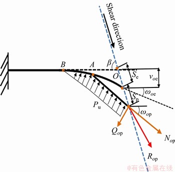
Figure 11 Relationship between displacement and rotation angle of bolt in plastic stage
For the calculation of the axial force at point C, the bolt can be regarded as a linear reinforced elastoplastic material, and its stress-strain relationship is simplified as shown in Figure 12. σs is the yield strength of the material, and εe is the strain corresponding to the yield strength of the material. The strain in the bolt material is very small in the elastic stage, and it can be reasonably assumed that point A and point O enter the plastic stage at the same time. The axial force at point C in the plastic stage can be expressed as:
 (21)
(21)
where Ep is the plastic modulus.
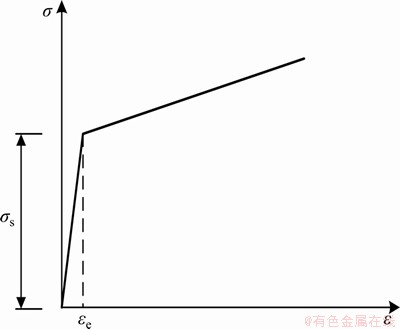
Figure 12 Stress-strain relationship of linearly strengthened elastoplastic materials
Substituting Eqs. (20) and (21) into Eq. (5) yields:

 (22)
(22)
where NOp is the axial force on point O in the plastic stage.
4.3 Yield criterion
Under the action of the shear force and axial force, the bolt first yields at the maximum bending moment point A. The elastic limit of the rock bolt at the hinge point A can be expressed as:
 (23)
(23)
where Wb is the section modulus and 
The bending moment MA at point A is proposed by PELLET et al [32] based on the moment equilibrium at A, as shown in Figure 8:
 (24)
(24)
Substituting Eq. (24) into Eq. (23) yields:
 (25)
(25)
Equation (25) is the elastic limit of the bolt at hinge point A.
4.4 Shear strength contribution of rock bolt
As shown in Figure 13, the contribution of the bolt to the shear strength is a combination of the axial force and shear force, decomposing the axial force NO and the shear force QO parallel to the joint direction and perpendicular to the joint direction yields Rot and Ron, i.e., the components parallel and perpendicular to the joint, respectively. The former provides an increment of cohesive force to the rock joint, and the latter provides an additional normal load on the joint surface while increasing the friction on the joint surface. These behaviours are called the cohesive force enhancement effect and the friction enhancement effect, respectively. The shear strength contribution of the bolt is the sum of the two effects.
Based on the Mohr-Coulomb criterion, the following formula can be used to compute the shear force contribution of the rock bolt:
 (26)
(26)
 (27)
(27)
 (28)
(28)
where τ is the shear strength contribution of the bolt;Cb is the additional cohesion of the bolt on the joint surface; σb is the additional normal force of the bolt on the joint surface; and f j is the joint friction angle.
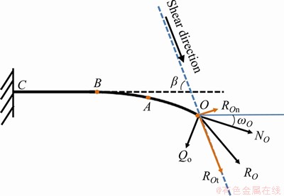
Figure 13 Force of bolt under shear action
5 Model validation
The calculation procedure of the model is shown in Figure 14. First, we calculate the axial force NC at point C, the shear force QO and the rotation angle at point O; then, we calculate the axial force NO at point O; and finally, we substitute NO and QO into Eq. (26) to obtain the shear force contribution of the bolt. The global shear load on the bolted rock joint is obtained by adding the shear contribution of the bolt and the shear contribution of the joint surface. Set the shear displacement increment as 0.1mm and iterate for 100 times.
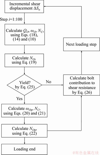
Figure 14 Calculation procedure of proposed model
The calculated and experimental values of the shear load of the bolted rock joints are shown in Figure 15. Additionally, the values calculated by the model without considering the effect of the bolt guide rail effect are compared to these results. The results show that the calculated shear load considering the bolt guide rail effect agrees well with the test results, indicating that the analysis and assumptions of the shear behaviour of the bolted rock joints are reasonable and applicable. When the model does not consider the effect of the bolt guide rail, the calculated values of the shear load agree well with the experimental values when the normal stress is small. When the normal stress increases, the calculated value is significantly larger than the experimental value, and the error gradually increases. The predicted value in the elastic stage is generally larger than the corresponding experimental value because the strain in the bolt in the elastic stage is very small, usually only 0.5%, and the dowel shear force of the bolt can quickly reach the peak. In the shear test, the bolt, grout and rock mass form an integrated system. The shearing process may be accompanied by compaction between the components or with the shear box, resulting in the dowel shear force hysteresis, resulting in the shear stiffness of the predicted curve being greater than that of the test curve.
In practical engineering, prestress should be applied to the rock bolt, and prestress can increase the normal stress of the joint surface, thereby increasing the shear strength of the bolted rock joint. Hence, at point C, the total axial force is composed of two components:
 (29)
(29)
where Tpre is the applied pretension force and NCS is the axial force mobilized at point C due to the bolt slip and can be computed by Eq. (10). Then, the expression for the attenuation parameter g becomes:
 (30)
(30)
Hence, considering the pretension force, the axial force expression of point O is:
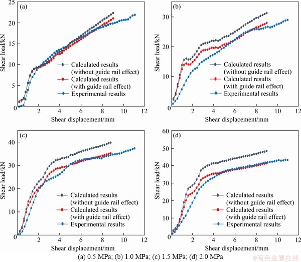
Figure 15 Comparison between calculated values and experimental values:

 (31)
(31)
We carry out direct shear tests with a normal stress of 1.0 MPa under pretension forces of 2 and 5 kN. Figure 16 shows a comparison of the shear load-shear displacement curves for the experiments and the analytical model under the two different pretension forces. The pretension forces increase the shear loads of the bolted rock joints. Larger pretension forces result in a larger shear load. The proposed model successfully captures the pretension effects and closely matches the experimental shear load-shear displacement curves.

Figure 16 Experimental values and calculated values under different prestresses
6 Discussion
In this study, the mechanical behaviour of a fully grouted rock bolt under shear action is analysed, and we propose an analytical model of the axial force, shear force and shear displacement of the bolt. The model helps reveal the mechanical characteristics of a fully grouted rock bolt.
FERRERO [30], PELLET et al [32] and MA et al [34] provided analytical models for estimating the axial force, shear force and displacement of the bolt, but their models did not consider the inhibitory effect of the normal stress on the bolt guide rail effect. In comparison, the model developed here considers this effect. In addition, our model considers the bolt as a bending rod with an increasing bending angle and establishes the static balance of the bending rod to describe the axial load transfer mechanism. The experimental verification shows that the model can better predict the variation in the axial force on the bolt under different normal stresses.
Certain factors may cause errors in the established analysis model. First, in reality, the mechanical properties and confining pressure of natural rock masses are spatially variable. The model considers the rock to be homogeneous for simplicity. Second, for the sake of simplicity, the analysis model in this paper does not consider the bonding force of the grout-bolt interface. Because the bonding force of the laboratory test size is small, its influence is ignored in this study. Finally, the influence of the guide rail effect on the bolt dowel shear force is not considered in the model. Figure 4 shows that within a certain range, the bolt bending angle demonstrates a positive linear correlation with the normal stress. When the normal stress increases, the guide rail effect weakens, the bolt bending deformation increases, and the bolt dowel shear force increases. Therefore, it is necessary to conduct experiments to further analyze and verify the effect of the bolt rail on the dowel shear force.
7 Conclusions
The direct shear testing of bolted rock joints under 4 levels of normal stresses is carried out, and the relationships between the normal stress, bolt bending angle and bolt axial force are analyzed. The test results show that during the shearing process of bolted rock joints, the rock mass will slide along the bolt similar to sliding along a rail, which is called the bolt guide rail effect. With increasing normal stress, the guide rail effect weakens, which restricts rock blocks from climbing along the bolt, reduces the axial deformation of the bolt, and causes the axial force on the bolt to play a smaller role.
This work analyzes the shear mechanical behaviour of fully grouted bolted rock joints while taking into account factors such as the bolt properties, grout strength, and bolt inclination angles, with a focus on the inhibition of the bolt guide rail effect by the normal stress. Based on the axial load transfer mechanism of curved members, an analytical model for the shear mechanical behaviour of bolted rock joints is proposed. The established model incorporates the elastic and plastic stages. The estimated shear loads obtained by the analytical model agree well with the shear test values, indicating that the analytical model can predict the shear load-shear displacement curve for bolted rock joints well.
Contributors
ZHENG Luo-bin provided the concept and edited the draft of manuscript. WANG Liang-qing reviewed and edited draft of the manuscript and provided financial support. ZHU Lin-feng edited the draft of manuscript.
Conflict of interest
ZHENG Luo-bin, WANG Liang-qing, and ZHU Lin-feng declare that they have no conflict of interest.
References
[1] CHE Na, WANG Hua-ning, JIANG Ming-jing. DEM investigation of rock/bolt mechanical behaviour in pull-out tests [J]. Particuology, 2020, 52: 10-27. DOI: 0.1016/ j.partic.2019.12.006.
[2] ZOU Jin-feng, ZHANG Peng-hao. Analytical model of fully grouted bolts in pull-out tests and in situ rock masses [J]. International Journal of Rock Mechanics and Mining Sciences, 2019, 113: 278-294. DOI: 10.1016/j.ijrmms.2018.11.015.
[3] ITO F, NAKAHARA F, KAWANO R, KANG S S, OBARA Y. Visualization of failure in a pull-out test of cable bolts using X-ray CT [J]. Construction and Building Materials, 2001, 15(5, 6): 263-270. DOI: 10.1016/S0950-0618(00)00075-1.
[4] MENG Xiang-rui, ZHANG Ruo-fei, LI Ying-ming, JIANG Wei, YUAN Ying-hong, JI Guo-qing. Stress distribution law and influence factors of full-length anchorage FRP bolts [J]. Journal of Mining and Safety Engineering, 2019, 36(4): 678-684. http://www.cnki.com.cn/Article/CJFDTotal-KSYL 201904005.htm. (in Chinese)
[5] XIAO Tong-qiang, LI Hua-min, LI Hai-yang, WANG Meng. Pull-out properties of bolt with different anchorage length [J]. Journal of Mining and Safety Engineering, 2017, 34(6): 1075-1080. http://www.cnki.com.cn/Article/CJFDTotal-KS YL201706006.htm. (in Chinese)
[6] ZHANG Wei, LIU Quan-sheng. Synthetical deformation analysis of anchor bolt in jointed rock mass [J]. Rock and Soil Mechanics, 2012, 33(4): 1067-1074. http://www.cnki.com. cn/Article/CJFDTotal-YTLX201204017.htm. (in Chinese)
[7] GE Xiu-run, LIU Jian-wu. Study on shear resistance behavior of bolted rock joints [J]. Chinese Journal of Geotechnical Engineering, 1988, 10(1): 8-19. http://www.cnki.com.cn/ Article/CJFDTotal-YTGC198801001.htm. (in Chinese)
[8] SRIVASTAVA L P, SING M. Effect of fully grouted passive bolts on joint shearstrength parameters in a blocky mass [J]. Rock Mech Rock Eng, 2015, 48: 1-10. DOI: 10.1007/ s00603-014-0615-8.
[9] CHEN Yu, LI C C. Performance of fully encapsulated rebar bolts and D-bolts under combined pull-and-shear loading [J]. Tunnelling Underground Space Technol, 2015, 45: 99-106. DOI: 10.1016/j.tust.2014.09.008.
[10] LI Xu-wei, AZIZ N, MIRZAGHORBANALI A, NEMCIK J. Behavior of fiber glass bolts, rock bolts and cable bolts in shear [J]. Rock Mech Rock Eng, 2016, 49: 2723-2735. DOI: 10.1007/s00603-015-0907-7.
[11] RASEKH H, AZIZ N, MIRZA A, NEMCIK J, LI Xu-wei, YANG Guan-yu, KHALEGHPARAST S. Double shear testing of cable bolts with no concrete face contacts [J]. Procedia Engineering, 2017, 191, 2017: 1169-1177. DOI: 10.1016/j.proeng.2017.05.292.
[12] GRASSELLI G. 3D Behaviour of bolted rock joints: Experimental and numerical study [J]. International Journal of Rock Mechanics and Mining Sciences, 2005, 42(1): 13-24. DOI: 10.1016/j.ijrmms.2004.06.003.
[13] WU Qiong, JIANG Yao-fei, TANG Hui-ming, LUO Hong-ming, WANG Xiao-han, KANG Jin-tao, ZHANG Shu, YI Xin, FAN Liang-liang. Experimental and numerical studies on the evolution of shear behaviour and damage of natural discontinuities at the interface between different rock types [J]. Rock Mechanics and Rock Engineering, 2020, 53: 3721-3744. DOI: 10.1007/s00603-020-02129-9.
[14] LIU Cai-hua, LI Yu-zong. Predicting the shear resistance contribution of passive fully grouted bolts to jointed rock [J]. International Journal of Geomechanics, 2020, 20(2): 04019174. DOI:10.1061/(ASCE)GM.1943-5622.0001581.
[15] LIN Hang, SUN Peng-hui, CHEN Yi-fan, ZHU You-yan, FAN Xiang, ZHAO Yan-lin. Analytical and experimental analysis of the shear strength of bolted saw-tooth joints [J]. European Journal of Environmental and Civil Engineering, 2020, 1: 1-15. DOI: 10.1080/19648189.2020.1726822.
[16] CHEN Na, ZHANG Xiao-bo, JIANG Qing-hui, FENG Xi-xia, WEI Wei, YI Bing. Shear behaviour of rough rock joints reinforced by bolts [J]. International Journal of Geomechanics, 2018, 18(1): 04017130. DOI: 10.1061/(ASCE)GM.1943-5622.0001048.
[17] WU Xue-zhen, JIANG Yu-jing, GONG Bin, GUAN Zhen-chang, DENG Tao. Shear performance of rock joint reinforced by fully encapsulated rock bolt under cyclic loading condition [J]. Rock Mechanics & Rock Engineering, 2019, 52: 2681-2690. DOI: 10.1007/s00603-018-1698-4.
[18] LI L, HAGAN P C, SAYDAM S, HEBBLEWHITE B, LI Y. Parametric study of rockbolt shear behaviour by double shear test [J]. Rock Mech Rock Eng, 2016, 49(12): 4787-4797. DOI: 10.1007/s00603-016-1063-4.
[19] LIU Quan-sheng, LEI Guang-feng, PENG Xing-xin, WEI Lai, LIU Jian-ping, PAN Yu-cong. Experimental study and mechanism analysis of influence of bolt anchoring on shear properties of jointed rock mass [J]. Rock and Soil Mechanics, 2017, 38(S1): 27-35. DOI: 10.16285/j.rsm.2017.S1.003. (in Chinese)
[20] SPANG K, EGGER P. Action of fully-grouted bolts in jointed rock and factors of influence [J]. Rock Mechanics and Rock Engineering, 1990, 23: 201-229. DOI: 10.1007/BF01022954.
[21] LUDVID B. Shear tests on rock bolts [C]// Proceedings of International Symposium on Rock Bolting. Balkema: Abisko, 1983: 113-123. https://www.researchgate.net/publication/ 284616968_Shear_tests_on_rock_bolts.
[22] CUI Guo-jian, ZHANG Chuan-qing, Chen Jian-lin, YANG Fan-jie, ZHOU Hui, LU Jing-jing. Effect of bolt inclination angle on shear behavior of bolted joints under CNL and CNS conditions [J]. Journal of Central South University, 2020, 27: 937-950. DOI: 10.1007/s11771-020-4342-x.
[23] WU Xue-zhen, JIANG Yu-jing, GONG Bin, GUAN Zhen-chang, DENG Tao. Shear performance of rock joint reinforced by fully encapsulated rock bolt under cyclic loading condition [J]. Rock Mechanics & Rock Engineering, 2019, 52: 2681-2690. DOI: 10.1007/s00603-018-1698-4.
[24] YOSHINAKA R, SAKGUCHI S, SHIMIZU T, ARAI H, KATO E. Experimental study on the rock bolt reinforcement in discontinuous rocks [J]. Electronics & Communications in Japan, 1987, 133(113): 117-127. DOI: info:doi/10.1002/ ecj.11645.
[25] HASS C J. Analysis of rock bolting to prevent shear movement in fractured ground [J]. Journal of Mining Engineering, 1981, 33(6): 698-704. https://www.sci-hub.ren/10.1016/0148-9062(81)90710-5.
[26] SONG Hong-wei, DUAN Yan-yan, YANG Jing. Numerical simulationon bolted rock joint shearing performance [J].International Joural of Mining Science and Technology, 2011, 20(3): 460-465. DOI: 10.1016/S1674-5264(09)60226-X.
[27] SONG Hong-wei. New study on transverse effect of rock bolts in discontinuous rock mass [J]. Journal of China University of Mining & Technology, 2003, 32(2): 161-164. http://en.cnki. com.cn/Article_en/CJFDTOTAL-ZGKD20030 2016.htm. (in Chinese)
[28] JIA Ying-xuan, SONG Hong-wei, DUAN Yan-yan. Physical simulation study on rail way Effect of bolt in discontinuous rock mass [J]. Journal of China University of Mining & Technology, 2007, 36(4): 614-617. DOI: 10.1016/S1872-2032(07)60057-2. (in Chinese)
[29] KAWAKATA H, CHO A, KIYAMA T, YANAGIDANI T, KUSUNOSE K, SHIMADA M. Three-dimensional observations of faulting process in Westerly granite under uniaxial and triaxial conditions by X-ray CT scan [J]. Tectonophysics, 1999, 313: 293-305. DOI: 10.1016/S0040-1951(99)00205-X.
[30] FERRERO A M. The shear strength of reinforced rock joints [J]. International Journal of Rock Mechanics and Mining Sciences & Geomechanics Abstracts, 1995, 32(6): 595-605. DOI: 10.1016/0148-9062(95)00002-X.
[31] LI Yu-zong, LIU Cai-hua, Experimental study on the shear behavior of fully grouted bolts [J]. Construction and Building Materials, 2019, 223: 1123-1134. DOI: 10.1016/ j.conbuildmat.2019.06.207.
[32] PELLET F, EGGER P. Analytical model for the mechanical behaviour of bolted rock joints subjected to shearing [J]. Rock Mech Rock Eng, 1996, 29(2): 73-97. DOI: 10.1007/BF01079755.
[33] ZHAO Zeng-hui, GAO Xiao-jie, TAN Yun-liang, MA Qing. Theoretical and numerical study on reinforcing effect of rock-bolt through composite soft rock-mass [J]. Journal of Central South University, 2018, 25: 2512-2522. DOI: 10.1007/ s11771-018-3932-3.
[34] MA Shu-qi, ZHAO Zhi-ye, SHANG Jun-long. An analytical model for shear behaviour of bolted rock joints [J]. International Journal of Rock Mechanics and Mining Sciences, 2019, 121: 104019. DOI: 10.1016/j.ijrmms.2019. 04.005.
[35] CHEN Yu, WEN Guan-ping, HU Jian-hua. Analysis of deformation characteristics of fully grouted rock bolts under pull-and-shear loading [J]. Rock Mechanics and Rock Engineering, 2020, 53: 2981-2993. DOI: 10.1007/s00603-020-02108-0.
[36] MURALHA J, GRASSELLI G, TATONE B, BLUMEL M, CHRYSSANTHAKIS P, JIANG Yu-jing. ISRM suggested method for laboratory determination of the shear strength of rock joints: Revised version [J]. Rock Mech Rock Eng, 2014, 47: 291-302. DOI: 10.1007/978-3-319-07713-0_10.
[37] MA Shu-qi, NEMCIK J, AZIZ N. An analytical model or fully grouted rock bolts subjected to tensile load [J]. Construction and Building Materials, 2013, 49: 519-526. DOI: 10.1016/j.conbuildmat.2013.08.084.
[38] MORADI A R, SOLTANI M, TASNIMI A A. A simplified constitutive model for dowel action across RC cracks [J]. J Adv Concr Technol, 2012, 10(8): 264-277. DOI: 10.3151/jact.10.264.
(Edited by FANG Jing-hua)
中文导读
考虑法向应力对锚杆导轨效应影响的锚固节理剪切力学特性分析模型
摘要:锚杆被广泛应用与边坡岩体的加固。由于影响锚杆轴力和剪力的因素过于复杂,因此,建立锚固节理剪切力学分析模型十分困难。锚杆在剪切作用下表现出导轨效应,即岩体会沿着像轨道一样的锚杆滑动。节理面的法向应力可以抑制导轨效应,从而降低锚杆中的轴力的发挥,然而,现有的分析模型没有考虑到这一影响因素。为了研究法向应力对锚杆导轨效应影响,开展不同法向应力下的锚固节理剪切试验,采用应变片记录锚杆各监测点的轴向应变,研究了锚杆轴力随法向应力增大而衰减的规律。基于轴力的衰减规律,提出了一种考虑法向应力对锚杆轨道效应抑制作用的锚固节理剪切力学分析模型,该模型兼顾了锚杆弹性阶段和塑性阶段的剪切特性,可以较好地预测锚固节理的剪切力学行为。模型预测值与室内直剪试验结果吻合较好。验证表明,该模型能有效地描述锚杆在剪切试验中的变形特性。
关键词:锚固节理;剪切试验;剪切行为;分析模型
Foundation item: Projects(41931295, 41877258) supported by the National Natural Science Foundation of China; Project(2017YFC1501305) supported by the National Key Research and Development Program of China
Received date: 2020-05-09; Accepted date: 2020-12-06
Corresponding author: WANG Liang-qing, PhD, Professor; Tel: +86-27-67883124; E-mail: wlq027@126.com; ORCID: https://orcid.org/ 0000-0001-9584-5812

