Upper bound analysis of slope stability with nonlinear failure criterion based on strength reduction technique
��Դ�ڿ������ϴ�ѧѧ��(Ӣ�İ�)2010���4��
�������ߣ������� ���� ��� ��ǿ ����
����ҳ�룺836 - 844
Key words��nonlinear failure criterion; strength reduction method; upper-bound theorem of limit analysis; slope stability analysis; factor of safety
Abstract: Based on the upper bound limit analysis theorem and the shear strength reduction technique, the equation for expressing critical limit-equilibrium state was employed to define the safety factor of a given slope and its corresponding critical failure mechanism by means of the kinematical approach of limit analysis theory. The nonlinear shear strength parameters were treated as variable parameters and a kinematically admissible failure mechanism was considered for calculation schemes. The iterative optimization method was adopted to obtain the safety factors. Case study and comparative analysis show that solutions presented here agree with available predictions when nonlinear criterion reduces to linear criterion, and the validity of present method could be illuminated. From the numerical results, it can also be seen that nonlinear parameter m, slope foot gradient ��, height of slope H, slope top gradient �� and soil bulk density �� have significant effects on the safety factor of the slope.
J. Cent. South Univ. Technol. (2010) 17: 836-844
DOI: 10.1007/s11771-010-0564-7![]()
ZHAO Lian-heng(������), LI Liang(����), YANG Feng(���), LUO Qiang(��ǿ), LIU Xiang(����)
School of Civil and Architectural Engineering, Central South University, Changsha 410075, China
? Central South University Press and Springer-Verlag Berlin Heidelberg 2010
Abstract: Based on the upper bound limit analysis theorem and the shear strength reduction technique, the equation for expressing critical limit-equilibrium state was employed to define the safety factor of a given slope and its corresponding critical failure mechanism by means of the kinematical approach of limit analysis theory. The nonlinear shear strength parameters were treated as variable parameters and a kinematically admissible failure mechanism was considered for calculation schemes. The iterative optimization method was adopted to obtain the safety factors. Case study and comparative analysis show that solutions presented here agree with available predictions when nonlinear criterion reduces to linear criterion, and the validity of present method could be illuminated. From the numerical results, it can also be seen that nonlinear parameter m, slope foot gradient ��, height of slope H, slope top gradient �� and soil bulk density �� have significant effects on the safety factor of the slope.
Key words: nonlinear failure criterion; strength reduction method; upper-bound theorem of limit analysis; slope stability analysis; factor of safety
1 Introduction
Soil slope stability analysis plays a considerably vital part in the field of geotechnical and civil engineering, and it has aroused a lot of investigation. Common methods for slope stability analysis are as follows: limit equilibrium method, limit analysis theorem, slip-line field method and numerical analysis method [1]. Limit analysis theory has been widely used because of its definite physical significance and strict solving range. However, the main evaluation index of limit analysis for slope stability are critical height (Hcr) and stability factor (Ns) at present, which differ from the universal evaluation index of safety factor (Fs), thus causing lots of inconvenience to the soil slope stability analysis [1-2]. The issue that combines limit analysis theory with the strength reduction technique to comprehensively analyze the stability of slope has been seldom considered [3-6].
Meanwhile, the linear Mohr�CCoulomb (MC) failure criterion has been widely used in these efforts and techniques mentioned above. However, nearly all the experimental results show that the strength envelopes of almost all the geo-materials have the nature of nonlinearity, and that linear failure criterion is a special case of failure criteria [7-9].
A number of researchers have employed nonlinear failure criterion to calculate critical height (Hcr) and stability factor (Ns) of slopes with limit analysis theory [7-12] and finite element method [13]; and only few studies [14] have obtained the safety factors by using the limit equilibrium method. However, limit equilibrium method is usually taken as a non-strict solution according to the randomness on block dividing and the assumption on inter-force between blocks [1].
For the reasons mentioned above, by using upper bound limit analysis and strength reduction method, the main point of this work is to get the upper bound solution of safety factor (Fs) under the assumption of nonlinear failure criterion. The influences of nonlinear parameter m and other different parameters on slope safety factor (Fs) and latent slide surface were examined by using the iterative optimization method, and and some charts of safety factor (Fs)d with different nonlinear parameter m and other parameters were presented for practical use in engineering.
2 Basic principle and assumptions
2.1 Strength reduction technique
Strength reduction technique was proposed by BISHOP in 1955 [15]. The shear strength parameters (c and ��) are divided by slope safety factor (Fs), which are analytically defined as Eq.(1), and make the slope reach a critical state.
![]() (1)
(1)
where safety factor Fs serves as the reduction factor of shear strength parameters; c is the cohesive strength; �� is the internal friction angle; cf is the reduced cohesive strength; and ��f is the reduced internal friction angle.
2.2 Upper bound analysis based on strength reduction method for slope stability
According to strength reduction technique, substituting the reduced shear strength parameters into the expression of virtual work principle, the limit analysis theory can be combined with reduction theorem following a certain stability criterion. For a slope, this upper bound analytic process can be described as follows: if a kinematically admissible failure mechanism is available, the safety factor is equal to 1.0 when the slope height arrives at critical height Hcr. Thus, under certain conditions of a actual slope height Hactual, the slope stays at stable state when the actual slope height Hactual is just right greater than or equal to critical height (Hcr) after deducing the strength parameters (c and ��). At this moment, Hactual=Hcr can be regarded as the evaluation index of the slope stability, and the reduction factor of original strength parameters is precisely the safety factor (Fs) of slope stability [4-6].
2.3 Nonlinear yield criterion and energy dissipation
The experimental results show that strength envelopes of almost all geo-materials have the nature of nonlinearity in ��n�C�� stress space, a nonlinear M-C yield criterion can usually be expressed as [8]
![]() (2)
(2)
where ��n and �� are normal and shear stresses on failure envelope (or surface), respectively; and c0, ��t and m are test parameters and can be determined by test. When nonlinear parameter m=1, Eq.(2) reduces to the well-known linear M-C yield criterion.
A limit load computed from a pyramidal failure surface, which always circumscribes the actual failure surface, will be an upper bound on the actual limit load [3]. Thus, the linear MC failure criterion represented by the tangential line will give an upper bound on the actual load for the material, whose failure is governed by the nonlinear failure criterion. By adopting this idea, a tangential line to the nonlinear yield criterion, is employed by YANG et al [10-12] to calculate the energy dissipation of geo-materials, to avoid the calculation difficulty under the nonlinear failure criterion. A more comprehensive description of this method can be found in Refs.[10-12].
A mobilized internal friction angle ��t as an intermediate variable is introduced as of tan ��t=d��/d��n, the tangential line to the curve at the location of tangency point can be expressed as
![]() (3)
(3)
where ct is the intercept of the tangential line on the ��-axis. ct is determined by the following expression:
 (4)
(4)
As for nonlinear failure criterion, the original strength indexes (c and ��) are to be altered into nonlinear shear strength indexes ct and ��t as tangential line method as follows:
![]() (5)
(5)
2.4 Basic assumptions
In order to solve the stability problem of slopes, some assumptions have been made.
(1) The slope is long enough, .Tand this problem can be regarded as a plane strain problem.
(2) The filling is idealized as a perfectly plastic material, and follows the associated flow rule.
(3) The rate of external work is due to soil weight, and the contribution to energy dissipation is provided along the failure surface.
3 Calculation for safety factor of slope
In this work, a rotational failure mechanism following a log-spiral slip surface is shown in Fig.1, where ��' is the angle related line CC�� to line AC��; ��0 is the angle related horizontal line to line OB; and ��h is the angle related horizontal line to line OC��. This mechanism, which is considered by CHEN [2], is geometrically defined by angles ��, ��, ��', ��0, ��h and the mobilized internal friction angle ��t.
Calculations of the rate of work dissipation and the work rate of the soil weight for rotational mechanism can be found in CHEN [2]. Equating the work rate of external forces to the internal energy dissipation rate, the objective functions of safety factor Fs as follows:
![]() (6)
(6)
where Hactual denotes the actual slope height; functions
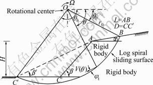
Fig.1 Rotational failure mechanism for slope stability analysis
for f1-f4 depend on angles ��h, ��0, ��, ��, ��', and ��t , and can be found in CHEN[2]. and can be found inA the upper bound theorem, the solution of Eq.(6) serves as a classical optimization problem, which gives both the values Fs. The least upper bound for safety factor Fs can be found by solving the following set of equations:
 (7)
(7)
In Eq.(7), the unknown quantities are ��h, ��0, �¡� and ��t; in effect, safety factor Fs is an implicit function at the same time. So, iterative optimization calculation is adopted to obtain the least upper bound for safety factor Fs by reducing nonlinear shear strength indexes (ct and ��t).
Once ��h, ��0, �¡�, ct and ��t are found, the geometry of the critical failure surface is completely defined. L and D are useful parameters to draw the position of the potential sliding surface in Fig.1. There are
![]() (8)
(8)
and
![]() (9)
(9)
where L expresses the distance between the failure surface at crest and edge of the slope; D represents the distance between the failure surface at bottom of the slope and slope toe, and D=0 means the slipping surfaces passing through the slope toe.
4 Comparisons and analysis
4.1 Comparison with calculation on linear failure criterion
An embankment slope example based on linear failure criterion was cited to illustrate the validity of this method. The parameters in this example are as follows: slope height H=6 m, slope top gradient ��=0?, slope foot gradient ��=55?, soil bulk density ��=18.6 kN/m3, cohesion force c=16.7 kN/m2 and internal friction angle ��=12?. Comparisons were made with different methods (simplified bishop method, Swedish slice method, Janbu method and finite difference method) on safety factor and latent slip surface, which are outlined in Fig.2.
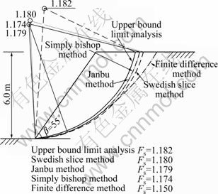
Fig.2 Comparison of different methods on critical sliding surfaces and safety factor based on linear failure criterion
As seen from Fig.2, slope safety factor obtained by present method has little difference withas that by other methods, and absolute error is no more than 2.1%; and the latent slip surfaces obtained by traditional limit-equilibrium methods are adjacent to each other, which can prove the validity of the validity of this method.
4.2 Comparison with calculation on nonlinear failure criterion
To show the validity of the present approach under the assumption of nonlinear failure criterion, the example, in which ��0=90 kN/m2, ��t=247.3 kN/m2 were used by ZHANG and CHEN [7], was chosen like other authors including DRESCHER and CHRISTOPOULOS [8], COLLINS et al [9], YANG and YIN [10] and LI [13]. Table 1 shows a comparison of stability factor Ns obtained by ZHANG and CHEN [7] with the results of stability factor Ns, critical height Hcr and corresponding safety factor Fs computed by the present solution. For the cases analyzed, seven values of nonlinear parameter m are taken into account from 1.0 to 2.5 and four slopes are considered with slope foot gradient �� varying from 45? to 90?. In addition, slope top gradient ��=0? and soil bulk density ��=20.0 kN/m3 are considered at the same time.
As shown in Table 1, for ��=90?, 75?, 60? and 45? with m=1.0-2.5, the most absolute difference between the present computational stability factor Ns and that obtained by ZHANG and CHEN [7] is 0.72%, 1.51%, 2.94% and 7.43%, respectively. And all of the present stability factor Ns solutions are less than those obtained by ZHANG and CHEN [7].In terms of the upper bound limit analysis method, the smaller the stability factor Ns, the better the upper bound solution.
Theoretically speaking, given a slope with certain parameters, it is true that safety factor (Fs) is 1.0 when slopes reach critical height (Hcr) and stability factor (Ns) [2-6]. Table 1 also shows safety factor (Fs) for all of the case mentioned above when slopes reach critical height (Hcr) and stability factor (Ns). From Table 1, it is obvious that safety factor Fs is equal to 1.000 for all cases, which means that the proposed method is an effective method for evaluating stability of slopes by with strength reduction technique under the condition of nonlinear failure criterion.
The corresponding effects of nonlinear parameter m on mobilized internal friction angle ��t and the intercept of tangential line on ��-axis ct are shown in Fig.3.
Fig.3 show sthat nonlinear parameter m is observed to have a notable influence on Form mobilized internal friction angle ��t and the intercept of tangential line on ��-axis ct for different slopes with slope foot gradient �� varying from 45? to 90?. The mobilized internal friction angle ��t reduces with a increasing m and the intercept of tangential line on ��-axis ct increase firstly and decreases afterwardfall with a increasing m, and the trend is more marked for a flat slope with ��=45?.
Table 1 Comparison of stability factors Ns obtained by ZHANG and CHEN [7] with results of stability factor Ns, critical height Hcr and corresponding safety factor Fs computed by present solution
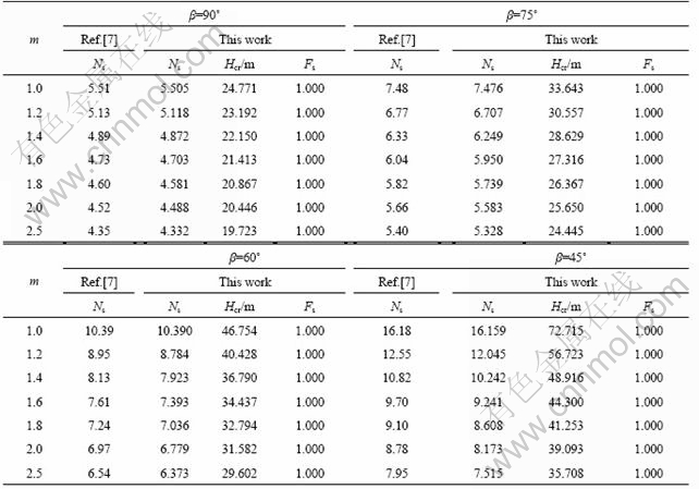

Fig.3 Effect of nonlinear parameter m on mobilized internal friction angle ��t and intercept of tangential line on ��-axis ct for different slopes with slope foot gradient �� varying from 45? to 90?: (a) ��t versus m; (b) ct versus m
5 Parameters analysisIn order to investigate the effect of safety factor Fs of a slopeare affected when a nonlinear yield criterion is used, and a series of cases are studied. The effects of nonlinear parameter m, slope foot gradient ��, slope height H, slope top gradient �� and soil bulk density �� on safety factor Fs and potential sliding surface of slopes are studied.
5.1 Influence of nonlinear parameter m and slope foot gradient �� on slope stability
Given a slope with H=25 m, ��=5?, ��=20 kN/m3, c0= 90 kN/m2, and ��t=247.3 kN/m2. When nonlinear parameter m has a variety of values (m=1.0~2.5) and slope foot gradient �� varying from 30? to 90?, safety factors figured out by upper bound analysis are outlined in Fig.4. Under the same conditions, the critical failure surfaces coefficients (L/H, D/H) versus nonlinear parameter (m) for different slopes are shown inshown Fig.5 in detail and the corresponding latent slip surfaces are shown in Fig.6.
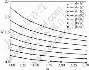
Fig.4 Effect of nonlinear parameter m on safety factor Fs for different slopes with �� varying from 30? to 90?
It is seenIt from Fig.4 that safety factor declines sharply with the rise of m, and other important outcome is slope foot gradient �� have a vital effect on Fs as well. For a flat slope with ��=30?, from m = 1.0 to m = 2.5, the absolute decrease on the safety factors Fs (from 2.238 8 to 1.482 6) is as high as 51.0%; and for vertical cut with ��=90?, from m = 1.0 to m = 2.5, the absolute decrease on safety factor Fs (from 0.9868 to 0.8028)is 22.9% to
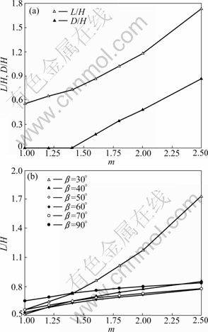
Fig.5 Critical failure surfaces coefficients (L/H and D/H) versus nonlinear parameter (m) for different slopes: (a) ��=30?; (b) ��=30?-90?
According to Figs.5 and 6, when other parameters remain unchanged, the latent slide surface moves towards the inner-slope with increase of m, the sliding surface becomes bigger, the failure mass is much larger than for linear case m=1.0, and safety factor declines sharply with rise of m at the same time. For a flat slope with ��=30?, from m = 1.0 to m = 2.5, the absolute increase on L/H (from 0.5562 to 1.7378) is as high as 212.4% ; and for vertical cut with ��=90?, from m = 1.0 to m = 2.5, theabsolute increase on L/H(from 0.6473 to 0.8364) 29.2% .
Another important outcome obtained form Figs.5 and 6is slope foot gradient �� have an effect on latent slide surface: the smaller the slope foot gradient ��, the larger the influence degree. For a certain slope with �� being equal or greaterlarger than or equal to 30?, slipping surfaces pass through the slope toe and D/H=0 in all of the cases as shown in Figs.6(b)-(d). Failure surfaces nearly have no intersection into foundation for linear failure criterion and the failure surfaces slightly penetrate into the foundation ground with the increase of m. But for a flat slope with ��=30?, from m = 1.0 to m = 2.5, the slipping surfaces pass through the slope toe firstly and deeply penetrate into foundation ground afterward.
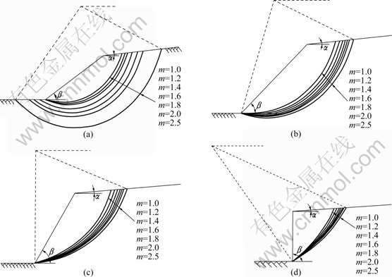
Fig.6 Comparison of potential sliding surface based on nonlinear failure criterion for different �� values: (a) ��=30?; (b) ��=40?; (c) ��= 60?; (d) ��=90?
5.2 Influence of nonlinear parameter m and height of slope H on slope stability
Given a slope with ��=60?, ��=10?, ��=20 kN/m3, c0= 90 kN/m2, ��t=247.3 kN/m2. When nonlinear parameter m has a variety of values (m=1.0-2.5) and slope height H varies form 10 to 30 m, safety factor Fs figured out by upper bound analysis is outlined in Fig.7. Under the same conditions, the corresponding critical failure surfaces coefficient (L/H) versus the nonlinear parameter (m) for different slopes are shown in Fig.8in detail.
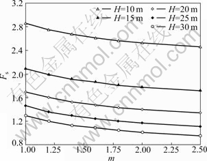
Fig.7 Effect of nonlinear parameter m on safety factor Fs for different slopes with H varying from 10 to 30 m

Fig.8 Effect of nonlinear parameter m on critical failure factor L/H for different slopes with H varying from 10 to 30 m
It is seen from Fig.7 that safety factor Fs decreases with the increase increaseof m and the riseH, but the degree of influence with the rise of H goes deeper. increaseFor a single slope with H=20 m, m=1.0 to m=2.5, the absolute decrease on safety factors Fs (from 1.6958 to 1.3357) is 27.0% ; and for a single slope with the nonlinear parameter m=2.0, from H = from10 to H = 30 m, the absolute decrease on safety factor Fs (from 2.5265 to 1.0066)is as high as 150.99% .
According to Fig.8, when other parameters remain unchanged under nonlinear failure criterion, latent slide surface moves towards the inner-slope with the increase increaseof m. Athe sliding surface becomes bigger, and the failure mass is much larger than that in the linear case (m=1.0). Slope height H have an effect on the latent slide surface as well, the smaller the slope height H, the larger the L/H. For sa single slope with H=20 m, from m= 1.0 the absolute increase on L/H (from 0.6666 to 0.9927) is 48.9% ; and for a single slope with nonlinear parameter m=1.8from H = 10m to H = 30m, the absolute decrease on L/H, (from 1.039 1 at to 0.791 5 at ) is 31.3%.
5.3 Influence of nonlinear parameter m and slope top gradient �� on slope stability
Given a slope with ��=75?, H=20 m, ��=20 kN/m3, c0=90 kN/m2, ��t=247.3 kN/m2. The theinfluences of ofnonlinear parameter m and slope top gradient �� on on slope stability are studied in this section. For the cases analyzed, seven values of nonlinear parameter m are taken into account from 1.0 to 2.5 and five slopes are considered with slope top gradient �� vary from 0? to 20?, and safety factor Fs is outlined in Fig.9. Under the same conditions, the curves of critical failure surfaces coefficient (L/H) versus nonlinear parameter (m) for different slopes are shown illustratedin Fig.10 in detail and the corresponding latent slip surfaces are shown in Fig.11.
It is seen from seen Fig.9 that safety factors Fs decrease with the increase of mand the rise of ��, but the degree of influence with the increase of m goes slightly deeperthat . For a single slope with ��=15?, from m = 1.0 to m = 2.5, the absolute decrease on safety factor Fs (from 1.3939 to 1.1179)is 24.7% ; and for a single slope with the nonlinear parameter m=2.0, �� ranging from 0? to 20?, safety factor Fs (from 1.2337 to 1.1187) is 10.3%shows ? ?.
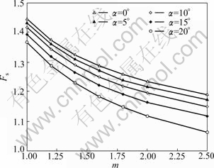
Fig.9 Effect of nonlinear parameter m on safety factor Fs for different slopes with �� varying from 0? to 20?
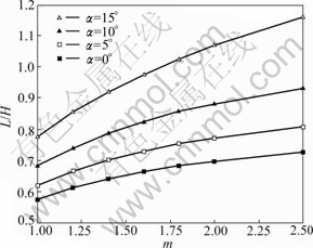
Fig.10 Effect of nonlinear parameter m on failure surface coefficient L/H with �� varying from 0? to 15?
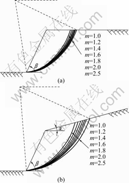
Fig.11 Comparison of potential sliding surface based on nonlinear failure criterion: (a) ��=0?; (b) ��=15?
According to Figs.10 and 11, when other parameters remain unchanged under nonlinear failure criterion, the latent slide surface moves towards the inner-slope with the increase increaseof m and ��, sliding surface becomes bigger, failure mass is slightly larger than the linear case (m=1.0), and safety factor declines gradually with the rise increaseof m at the same time.
Slope top gradient �� has a vital effect on latent slide surface as well, for a single slope with nonlinear parameter m=2.0, from ��= 0? to ��= 15?, the absolute increase on L/H (from 0.6978 to 1.0694)is as high as 53.3% .
5.4 Influence of nonlinear parameter m and soil bulk density �� on slope stability
Given a slope with ��=75?, ��=10?, H=20 m, c0= 90 kN/m2, ��t=247.3 kN/m2. The influences of nonlinear parameter m and soil bulk density �� on slope stability. For the cases analyzed, seven values of nonlinear parameter m are taken into account from 1.0 to 2.5 and slopes are considered with soil bulk density �� varying from 16 to 26 kN/m3, and safety factor Fs is figured out in Fig.12. Under the same conditions, the curves of critical failure surface coefficient (L/H) versus nonlinear parameter (m) for different slopes are shown shown in Fig.13 in detail and the corresponding latent slip surfaces are shown in Fig.14.
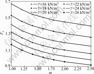
Fig.12 Effects of nonlinear parameter m on safety factor Fs for different slopes with �� varying from 16 to 26 kN/m3
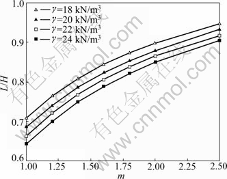
Fig.13 Critical failure surface coefficient L/H versus nonlinear parameter m for different slopes with �� varying from 18 to 24 kN/m3
It is from Fig.12 that safety factor Fs decrease with increase of m and the rise of ��, but the degree of influence with the rise of �� goes deeper. For a single slope with ��=20 kN/m3, from m = 1.0 to m = 2.5, the absolute decrease on safety factor Fs (from 1.4150 to 1.1502) is 23.0% ; and for a single slope with nonlinear parameter m= 2.0, and �� from 16 to 26 kN/m3, the absolute decrease on safety factor Fs (from 1.4456 to 0.9600) is 50.1%.
According to Figs.13 and 14, when other parameters remain unchanged under nonlinear failure criterion, the latent slide surface moves towards the inner-slope with the increase of m, sliding surface becomes bigger, failure mass is slightly larger than that for linear case m=1.0, and safety factor declines gradually with the rise increaseof m at the same time.
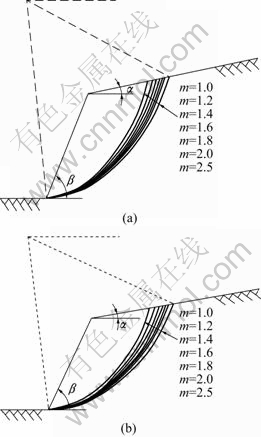
Fig.14 Comparison of potential sliding surface based on nonlinear failure criterion: (a) ��=20 kN/m3; (b) ��=24 kN/m3
It is seen
Soil bulk density �� has a certain effect on latent slide surface as well, for a single slope with nonlinear parameter m=2.0, from ��= 18kN/m3 to ��= 24kN/m3, absolute increaseon the L/H (from 0.8985 to 0.8500) is 5.7%decrease 24 .
6 Conclusions
(1) Case study and comparative analysis show that solutions presented here agree with available predictions when nonlinear criterion reduces to linear criterion, and the validity of present method can be illuminated.
(2) The effects of nonlinear parameter m, slope foot gradient ��, height of slope H, slope top gradient �� and soil bulk density �� are investigated by using log-spiral rotational fracture surface in upper bound method with nonlinear yield criterion. It is found that all these parameters have a significant influence on slope stability. Under the same conditions, safety factor Fs of slopes decrease non-linearly with stability condition of a slope deteriorates (increase in values of ��, ��, H and ��).
(3) The nonlinear strength parameter value of soil has a vital influence on evaluation slope stability, the safety factor Fs of slopes decreasing non-linearly and a deeper failure surface with a larger sliding wedge is observed with increase in values of m; consequently, it is crucial to introduce the assumption of nonlinear strength curve into the geo-material analysis.
Acknowledgments
Authors are grateful to ZHANG Ting for her assistance.
References
[1] ZHENG Ying-ren, CHEN Zu-yu, WANG Gong-xian, LING Tian-qing. Engineering treatment of slope and landslide [M]. Beijing: China Communication Press, 2007: 94-143. (in Chinese)
[2] Chen W F. Limit analysis and soil plasticity [M]. Amsterdam: Elsevier, 1975: 244-274.
[3] MICHALOWSKI R L. Slope stability analysis: A kinematical approach [J]. Geotechnique, 1995, 45(2): 283-293.
[4] AUSILIO E, CONTE E, DENTE G. Stability analysis of slopes reinforced with piles [J]. Computers and Geotechnics, ASCE, 2001, 28(8): 591-611.
[5] LI X P, H S M, WANG C H. Stability analysis of slopes reinforced with piles using limit analysis method [C]// Proceedings of Geo- Shanghai International Conference. Shanghai: Geotechnical Special Publication, 2006: 105-112.
[6] NIAN T K, CHEN G Q, LUAN M T, YANG Q, ZHENG D F. Limit analysis of the stability of slopes reinforced with piles against landslide in nonhomogeneous and anisotropic soils [J]. Canadian Geotechnical Journal, 2008, 45(8): 1092-1103.
[7] Zhang X J, Chen W F. Stability analysis of slopes with general nonlinear failure criterion [J]. International Journal for Numerical and Analytical Methods in Geomechanics, 1987, 11(1): 33-50.
[8] Drescher a, Christopoulos C. Limit analysis slope stability with nonlinear yield condition [J]. International Journal for Numerical and Analytical Methods in Geomechanics, 1988, 12(4): 341-345.
[9] Collins I F, Gunn C I M, Pender M J, Yan W. Slope stability analyses for materials with a non-linear failure envelope [J]. International Journal for Numerical and Analytical in Geomechanics, 1988, 12(5): 533-550.
[10] YANG Xiao-li, YIN Jian-hua. Slope stability analysis with nonlinear failure criterion [J]. Journal of Engineering Mechanics, 2004, 130(3): 267-273.
[11] YANG Xiao-li. Upper bound limit analysis of active earth pressure with different fracture surface and nonlinear yield criterion [J]. Theoretical and Applied Fracture Mechanics, 2007, 47(1): 46-56.
[12] YANG Xiao-li, HUANG Fu. Slope stability analysis considering joined influences of nonlinearity and dilation [J]. Journal of Central South University of Technology, 2009, 16(2): 292-296.
[13] LI X. Finite element analysis of slope stability using a nonlinear failure criterion [J]. Computers and Geotechnics, 2007, 34(1): 127-136.
[14] HU Wei-dong, ZHU Xin-nian, LI Xiao-qiang. Slope stability analysis with nonlinear failure criterion [J]. Journal of Hunan Institute of Science and Technology: Natural Sciences, 2006, 19(3): 85-91. (in Chinese)
[15] BISHOP A W. The use of the slip circle in the stability analysis of slopes [J]. Geotechique, 1955, 5(1): 7-17.
Foundation item: Project(2006318802111) supported by West Traffic Construction Science and Technology of China; Project(2008yb004) supported by Excellent Doctorate Dissertations of Central South University, China; Project(2008G032-3) supported by Key Item of Science and Technology Research of Railway Ministry of China
Received date: 2009-11-25; Accepted date: 2010-03-09
Corresponding author: ZHAO Lian-heng, PhD; Tel: +86-13755139425; E-mail: zlh8076@163.com

