Partial transient-liquid-phase bonding of TiC cermet to stainless steel using impulse pressuring with Ti/Cu/Nb interlayer
来源期刊:中南大学学报(英文版)2018年第5期
论文作者:盛光敏 黄利 LI Jia(李佳) 黄光杰 YUAN Xin-jian(袁新建)
文章页码:1025 - 1032
Key words:TiC cermet; transient liquid phase; impulse pressuring; mechanical property; fracture
Abstract: Partial transient liquid phase (PTLP) bonding of TiC cermet to 06Cr19Ni10 stainless steel was carried out. Impulse pressuring was used to reduce the bonding time, and a Ti/Cu/Nb interlayer was employed to alleviate the detrimental effect of interfacial reaction products on the bonding strength. Successful bonding was achieved at 885 °C under a pulsed pressure of 2–10 MPa within durations in the range of 2–8 min, which was notably shortened in comparison with conventional PTLP bonding. Microstructure characterization revealed the σ phase with a limit solubility of Nb, a sequence of Ti–Cu intermetallic phases and solid solutions of Ni and Cu in α+β Ti in the reaction zone. The maximum shear strength of 106.7 MPa was obtained when the joint was bonded for 5 min, indicating that a robust metallurgical bonding was achieved. Upon shear loading, the joints fractured along the Ti–Cu intermetallics interface and spread to the interior of TiC cermet in a brittle cleavage manner.
Cite this article as: HUANG Li, SHENG Guang-min, LI Jia, HUANG Guang-jie, YUAN Xin-jian. Partial transient-liquid-phase bonding of TiC cermet to stainless steel using impulse pressuring with Ti/Cu/Nb interlayer [J]. Journal of Central South University, 2018, 25(5): 1025–1032. DOI: https://doi.org/10.1007/s11771-018-3802-z.

J. Cent. South Univ. (2018) 25: 1025-1032
DOI: https://doi.org/10.1007/s11771-018-3802-z

HUANG Li(黄利)1, SHENG Guang-min(盛光敏)1, LI Jia(李佳)2,HUANG Guang-jie(黄光杰)1, YUAN Xin-jian(袁新建)1
1. College of Materials Science and Engineering, Chongqing University, Chongqing 400044, China;
2. Changan Commercial Vehicle Business Department, China Changan Automobile Group,Chongqing 400023, China
 Central South University Press and Springer-Verlag GmbH Germany, part of Springer Nature 2018
Abstract: Partial transient liquid phase (PTLP) bonding of TiC cermet to 06Cr19Ni10 stainless steel was carried out. Impulse pressuring was used to reduce the bonding time, and a Ti/Cu/Nb interlayer was employed to alleviate the detrimental effect of interfacial reaction products on the bonding strength. Successful bonding was achieved at 885 °C under a pulsed pressure of 2–10 MPa within durations in the range of 2–8 min, which was notably shortened in comparison with conventional PTLP bonding. Microstructure characterization revealed the σ phase with a limit solubility of Nb, a sequence of Ti–Cu intermetallic phases and solid solutions of Ni and Cu in α+β Ti in the reaction zone. The maximum shear strength of 106.7 MPa was obtained when the joint was bonded for 5 min, indicating that a robust metallurgical bonding was achieved. Upon shear loading, the joints fractured along the Ti–Cu intermetallics interface and spread to the interior of TiC cermet in a brittle cleavage manner.
Key words: TiC cermet; transient liquid phase; impulse pressuring; mechanical property; fracture
Cite this article as: HUANG Li, SHENG Guang-min, LI Jia, HUANG Guang-jie, YUAN Xin-jian. Partial transient-liquid-phase bonding of TiC cermet to stainless steel using impulse pressuring with Ti/Cu/Nb interlayer [J]. Journal of Central South University, 2018, 25(5): 1025–1032. DOI: https://doi.org/10.1007/s11771-018-3802-z.
1 Introduction
TiC cermet was a promising material due to its excellent combination of desirable properties at elevated temperature [1, 2]. However, the intensive application of TiC cermet is restricted for the poor workability originated from its inherent brittleness. A promising option to take advantage of the good characteristics of cermets was to combine it with other metals, such as steel.
Selecting appropriate filler metal is critical for brazing of TiC cermet to steel. The filler is required to be capable of accommodating their chemical and physical incompatibility, such as covalent nature of cermets and coefficient of thermal expansion (CTE) mismatch between these materials [3–5]. Conventional fusion welding was infeasible in the case of dissimilar materials joining of refractory TiC cermet (–3067 °C [6]) to steel owing to their different melting points, and would result in concentration of residual stress at the interface of the joints [7]. Partial transient liquid phase (PTLP) bonding, by contrast, has been demonstrated to be one of the most practicable methods to effectively bond ceramics to steels.
In PTLP bonding process, a eutectic liquid formed at the bonding interface allows the TiC cermet/steel joint formation at much lower bonding temperature than conventional connection methods, which was improved by TLP. [8, 9]. In terms of cermet/steel brazing, a series of Ti-, Cu-, Nb- and Ni-based interlayers have been well documented.
Recently, the Ti/Cu/Ti [10], Ti/Ni/Ti [11] and Ti/Cu/Ni [12] interlayers used for PTLP bonding of ceramics to metal have been reported. Ti was the most attractive active element for almost all the structure ceramics [13]. A thin Cu and Ni interlayer as melting point depressant was popularly used involving Ti because a low eutectic melting liquid-phase can be formed above 875 °C and 942 °C, respectively [14]. It was also reported by YANG et al [15] and MARKS et al [16] that the Si3N4/Inconel600 joint and Al2O3/Al2O3 joint can be achieved respectively, and the average shear strength can reach to 90–142 MPa. Soft Nb was a suitable candidate to buffer the residual stress in the ceramic/metal joints attributed to its lower CTE value (7.2×10⁻⁶ K–1) compared to ceramics (TiC cermet: 7.4×10⁻⁶ K–1) and steel ((12–13)×10–6 K–1) [6, 17]. Therefore, an interlayer Ti/Cu/Nb was required to be capable of accommodating the incompatible chemical and physical properties between TiC cermet and steel in the present study.
In spite of successful diffusion bonding achieved in above cases, it was noted that the diffusion bonding was time-consuming as 30–120 min was generally required to complete the bonding process [10–16]. A reduction in bonding time, which can retard the excessive growth of interfacial intermetallic compound (IMC), would be in turn potentially contributed to the bonding strength. In this regards, it was of great interest to shorten the bonding time by further optimizing the bonding circle, for the purpose of both productive efficiency and cost saving. Auxiliary impulse pressure can offer an advantage in the process of PTLP bonding because the pressure can enhance the speed of the atomic diffusion [18]. The compressive deformation generated by impulse pressure can fill voids and lead to titanium grain refining [19], which produced more grain boundaries to generate additional diffusion paths. Thus thermodynamically, all of these factors were in good shape to shorten the bonding time, and then accelerated the bonding process.
In the present study, a modified diffusion bonding technology, PTLP bonding using impulse pressuring with Ti/Cu/Nb interlayer was applied to realize robust bonding of TiC cermet to steel within a significantly reduced duration.
2 Experimental
The base materials, hot pressure sintering (HPS) TiC cermet and commercially stainless steel (SS, 06Cr19Ni10), were processed into 3 mm×4 mm×8 mm and 3 mm×8 mm×30 mm, respectively. As the multilayer metals, pure Ti, Cu, and Nb, with a thickness of 30 μm, 20 μm and 30 μm, were used. The chemical compositions and room temperature thermophysical properties of substrates and interlayer are given in Tables 1 and 2. The mating surfaces of the specimen were prepared by conventional grinding and polishing techniques, and subsequently cleaned in acetone to eradicate any residual contamination. The assembly sequence of samples was TiC–Ti–Cu–Nb-SS, as displayed in Figure 1(a). Bonding trials were performed in a Gleeble-1500D tester and the parameters were: temperature T=885 °C, pulsed compressive load pmin=2 MPa and pmax=10 MPa, impulse frequency f=0.5 Hz, bonding time t=2–8 min under a pulsed compressive load, in vacuum maintained at 1×10⁻³ Pa.
Subsequent to bonding, selected specimens were sectioned and microstructural observations were conducted in field emission scanning electron microscope (FEI-SEM, FEI Nova400) using back scattered mode (BSE) to reveal the interfacial reaction layers. Chemical concentration profile across the joints was determined using energy dispersive spectroscope (EDS). Room temperature shear tests were performed in a testing machine (Instron 1342) at a crosshead speed of 0.025 mm/min to examine the mechanical properties, as displayed in Figure 1. Fracture morphologies were observed by SEM, and X-ray diffraction (XRD) was used to identify phase at the fracture.
Table 1 Chemical composition of substrates (wt %)
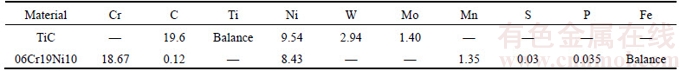
Table 2 Room temperature thermo-physical properties of Ti, Cu, Nb and substrates [6, 17]
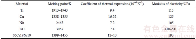
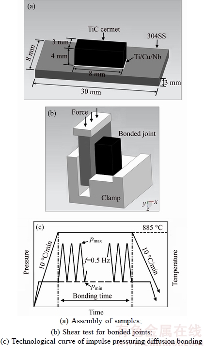
Figure 1 Schematic diagram
3 Results and discussion
3.1 Mechanical properties
Shear strength of the PTLP joints with the change of bonding time and the axial shear load–displacement curve are given in Figure 2. The shear strength was determined by the formula σ=F/S (σ was the strength, MPa; F was the loading, kN; and S was the bonded acreage of the sample, 3 mm×8 mm). The TiC cermet/SS joint was destroyed at the maximum load and then the load decreased suddenly, shown in Figure 2(b). This meant that fracture of the TiC cermet/SS joint was a brittle manner.
It was well known that the most important parameters for PTLP bonding, bonding temperature, pressure and bonding time, were not independent with each other. At a given temperature, the bonding time required to complete the bonding was a function of the applied pressure. A higher pressure would preferentially result in a reduced time required. At the short time range of 2–3.5 min, the joints exhibited a rather low strength of approximately 21–58.5 MPa. As the bonding time increased, so does the number of impulses (f=0.5 Hz). When t<5 min, elemental diffusion gradually increased as the number of impulses multiplies. The limited macroscopic deformation of the joint can be attributed to the increasing loading cycle the substrate experienced, which further promoted the atomic diffusivity [19]. It was thus deduced that the poor bonding quality of the joints was precisely because of the insufficient mass transfer of the reaction interface in such short bonding time. The joint strength was notably improved to 106.7 MPa when the bonding time increased to 5 min. The improvement can be attributed to the enhanced interdiffusion at the bonding interface. Obviously, atomic diffusivity was dominant in leading to the observed change since atomic diffusion has a decisive influence on forming the bonded joint, thereby affecting the strength of the joint significantly. However, when t>5 min, the joint shear strength decreased steadily, which can be ascribed to the ease of the deformation and thickening of brittle phases with a further increase in bonding time [20]. In all cases, the excellent mechanical property of joints indicated that good metallurgical bonding was achieved at the appropriate bonding parameters.

Figure 2 Shear strength measurement
3.2 Microstructure characterization
Detailed microstructure of the maximum strength joint bonded for 5 min studied by SEM is shown in Figure 3(a). The micrograph exhibited an excellent bonding along the interface of the bonded couples. A reaction and interdiffusion area was found at the TiC cermet/SS interface, and several distinct regions were observed on the micrograph. Corresponding elemental concentration profile of this joint was conducted to identify the phase constituent of the interfacial reaction layers, as shown in Figure 3(b).
The SS/Nb interface was planar in character. It can be seen that there was a thin diffusion zone “1” rich in Fe and Cr, which could be the formation of σ phase [14]. The average composition of this σ phase was Fe 65.5at %, Cr 24.8at %, Ni 3.5at % and Nb 6.2at %, as listed in Table 3. Owing to the reactive nature of Nb, metallurgical bonding can be readily formed at the SS/Nb interface via forming σ phase with a low solubility of Nb, as shown in Figure 3. However, since the mutual solubility of the Nb–σ phase system was limited, relatively prolonged duration was required to achieve adequate interdiffusion, which was a time-dependent process.
Adjacent to the SS/Nb interface, no element other than Nb can be detected from the elemental concentration profile. Therefore, this was the remnant Nb layer. The remnant Nb layer with low CTE value (7.2×10⁻⁶ K–1) between TiC cermet and SS can be a significant player to relieve the residual stress. Close to the remnant Nb interlayer, three distinct eutectic Cu–Ti layers, marked “2”, “3” and “4”, were also detected, and there was a plateau in the corresponding concentration profile of these layers. The average compositions of these layers respectively were: Ti 26.7 at %, Cu 71.8 at %, and Nb 1.5 at % in layer “2”; Ti 35.2 at %, Cu 60.5 at %, and Nb 4.3 at % in layer “3”; and Ti 64.7 at %,Cu 31.9 at %, and Nb 3.4 at % in layer “4”. XU et al [21] investigated the phase equilibria of the Cu–Nb–Ti system, which suggested that the solubility of Nb in Ti2Cu was determined to be 3.5 at %, whereas the solubility of Nb in TiCu4 was rather low, and the invariant reaction TiCu2 TiCu4+Ti2Cu3 should occur at 850 °C. In combination with the EDS results and the Cu–Nb–Ti ternary phase diagram, continuous IMC layers, including TiCu4, Ti2Cu3 and Ti2Cu, were generated from layer “2” to “4” attributed to the interdiffusion of Ti and Cu. The final thickness of the IMC layers was only about 22 μm after the isothermal solidification and solid phase homogenization, compared to the original Cu and Ti in the thickness of 50 μm. It was attributed to the impulse pressure, which crowded out partial liquid to reduce the thickness of IMC layers. Moreover, Nb and Cu played a role as diffusion barrier between Ti and SS, and Ti–Fe IMCs which have been recognized to be the most detrimental to the joint strength successfully inhibited.
Figure 3 SEM micrograph of joint interface at bonding time of 5 min (a) and corresponding elemental concentration profile (b)
Table 3 Chemical composition of marked regions in Figure 3(a)
Between the eutectic Cu–Ti layers and TiC substrate, a thin hybrid layer “5” was observed, with the average composition Ti (92.6 at %), Ni (5.1 at %) and Cu (2.3 at %). The diffusion distance of Ti and Ni from cermet to interface was about 5 μm. And the concentration profiles of both Ti and Ni in this layer exhibited smooth and continuous variations. Due to the diffusion of Ni, a β stabilizing element, towards the Ti substrate, led to the formation of β Ti phase at bonding temperature. Therefore, during the cooling stage, the hybrid α+β Ti was formed in this layer because the β Ti transformed to α+β Ti aggregate under the phase transformation point (882 °C) [22]. As the bonding proceeded, due to the solid state interdiffusion of elements, considerable mass transfer occurred and continuous transition layers were approached across the bonding interface.
3.3 Fracture analysis
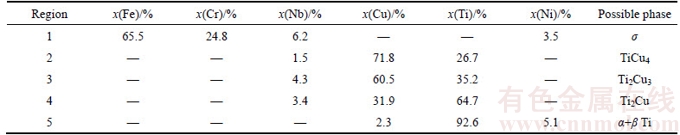
The fracture morphologies for all the TiC cermet/SS joints under the SEM micrograph, irrespective of the bonding parameters, appeared alike. A typical example of the maximum strength sample bonded under conditions of T=885 °C, p= 2–10 MPa, t=5 min, f=0.5 Hz is shown in Figure 4. The fracture surfaces as seen in Figure 4 consisted of gray matrix, white lumpy region and relatively few dark blocks of different sizes and distribution. The grains in the gray matrix magnified in Figure 4(b) showed isometric and coarse morphology, but not metallic shine, which can be deduced to be TiC cermet. By contrast, extensive cleavage patterns were observed in the lumpy region and dark blocks, magnified in Figures 4(c) and (d), respectively, from which it can be reasonably inferred that these regions were where the shear forces were concentrated, and the joints fail in a brittle manner.
To further investigate this characterization, the EDS technique was used to identify the elemental composition of the lumpy region and dark blocks on the fracture surfaces, given in Table 4. The average percentage of Cu and Ti in lumpy region was 58.44 at% and 41.56 at% respectively. According to the Cu–Ti phase diagram [14], the lumpy region was occupied mainly by Cu–Ti intermetallic phases. On the other hand, the average percentage of Cu and Ni in the dark blocks was only 2.1 at% and 4.9 at%, which was within the Cu and Ni solubility limit in α+β Ti.
To further verify the fracture location, the existence of the phases on the fracture surfaces has also been identified by XRD of a fractured specimen, displayed in Figure 5. The XRD patterns indicated that the Ti–Cu IMCs, (Ti, Ni) and TiC are detected on both sides of the fracture, while the Nb and γ Fe phase were only detected on SS side. The composition of (Ti, Ni) matched that of α+β Ti layer, and it can be inferred that fracture has taken place at the interface of the Cu–Ti intermetallic layers and spread to the TiC cermet layer. The presence of the Ti–Cu IMCs and the fracture of TiC cermet lead to decreasing the strength of the bonded joint, indicating that this is the weak point in the PTLP bonded joint.
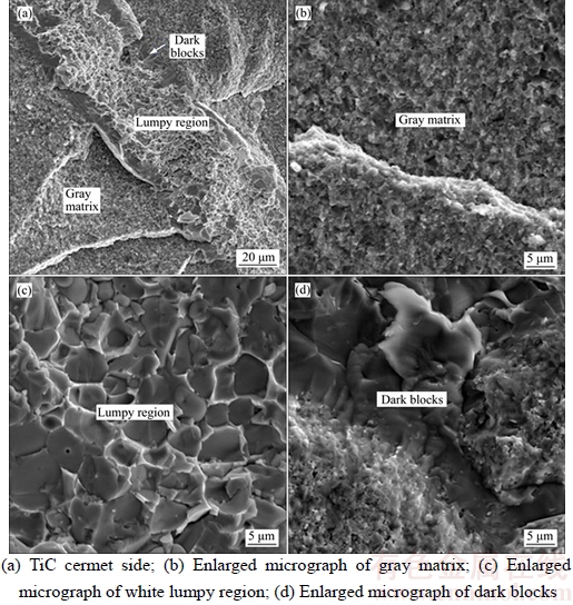
Figure 4 Fracture surface of sample
Table 4 EDS analysis of fracture surface in Figures 4(c) and (d)

ZDANIEWSKI et al [23] and BLUGAN et al [24] revealed that the residual stresses were at maximum within the ceramics closed to reaction interface, which explains the fracture extension to TiC cermet. The stresses resulted in crack formation at the gaps either due to the thermal expansion mismatch and subsequent differences in thermal contraction in cooling or by the applied loads during indentation. Because the CTE of SS was higher than that of TiC ceramic, the tensile residual stress σx parallel of the interface was always the largest within the joint, and in the free surface suddenly reduced to 0. In this work, a uniaxial compressive load of 2–10 MPa was applied along the longitudinal direction of sample in the process of bonding which results in the compressive stress σy perpendicular to the interface by lateral contraction of the ceramic and steel [23]. The addition of Nb (7.2×10⁻⁶ K–1) and Ti (9.4×10⁻⁶ K–1) should theoretically accommodate the mismatch between TiC cermet (7.4×10⁻⁶ K–1) and SS (12–13×10–6 K–1). The CTE values of new generated α+β Ti phases and Ti2Cu adjacent to TiC cermet were (9.41–10.03)×10–6 K–1 and 13.5×10⁻⁶ K–1 respectively [6, 17]. Thus, the residual stresses at TiC cermet/α+β Ti/Ti2Cu interface were alleviated. However, there was still the weak region in TiC cermet. In effect, the fracture was not only based on the CTE values, but also determined by the plastic deformation of brazed interface [25]. The ability of plastic deformation of brazed interface was reflected by the hardness of new phases indirectly because the low hardness corresponds to relatively high plasticity and ductility. It was obvious that the TiC substrate with the highest Vickers hardness (28–35 GPa) [6] has low fracture toughness due to its covalent nature. This indicated that the ability of plastic deformation of TiC cermet was weaker than that of other metal phases. Therefore, the fracture propagation was originated in Ti–Cu IMCs interface, and then spreaded to the TiC cermet in a typical brittle fracture manner, when exerting an external shear load upon the brazed joints.

Figure 5 XRD patterns of fracture surface
4 Conclusions
By utilizing impulse pressuring in combination of Ti/Cu/Nb interlayer, successful PTLP bonding of TiC cermet to commercially 06Cr19Ni10 SS can be achieved at 885 °C within duration of only 2–8 min under the bonding pressure of 2–10 MPa in vacuum. This technique provided a reliable and efficient diffusion bonding method of TiC cermet to stainless steel.
1) Adopting the PTLP bonding technique can shorten the bonding time notably.
2) The Ti–Cu–Nb interlayer can effectively promote the interdiffusion and reaction between TiC cermet and SS. The joints were characterized by the presence of the σ phase with a limited solubility of Nb, a sequence of Ti–Cu intermetallic phases and solid solutions of Ni and Cu in α+β Ti in the reaction zone, from SS to TiC side.
3) The maximum shear strength of 106.7 MPa can be achieved when the joints were bonded for 5 min. Upon shear loading, the fracture took place through the Ti–Cu IMCs interface to the interior of TiC cermet in a typical brittle fracture manner.
References
[1] LIU N, XU Y D, LI H. Effect of nano-micro TiN addition on the microstructure and mechanical properties of TiC based cermets [J]. J Eur Ceram Soc, 2002, 22(13): 2409–2414.
[2] SUN K N, YIN Y S, LI A M. Intermetallics/ceramic matrix composite [M]. Beijing: China Machine Press, 2002. (in Chinese)
[3] TRAVESSA D, FERRANTE M, DEN O G. Diffusion bonding of aluminium oxide to stainless steel using stress relief interlayers [J]. Mater Sci Eng A, 2002, 337(1): 287–296.
[4] SHEN X Q, LI Y J, PUTCHKOV U A. Finite-element analysis of residual stresses in Al2O3–TiC/W18Cr4V diffusion bonded joints [J]. Comp Mater Sci, 2009, 45(2): 407–410.
[5] YE D M, XIONG W H. Vacuum brazing of Ti(C, N) based cermets to 45 Steel [J]. Rare Metal Mat Eng,2008, 37(7): 1281–1284.
[6] PIERSON H O. Handbook of refractory carbides & nitrides: Properties, characteristics, processing and apps [M]. William Andrew, 1996.
[7] GOMEZ-DE-SALAZAR J M, BARRENA M I. Dissimilar fusion welding of AA7020/MMC reinforced with Al2O3 particles, microstructure and mechanical properties [J]. Mater Sci Eng A, 2003, 352(1): 162–168.
[8] BARRENA M I, GOMEZ-DE-SALAZAR J M, MATESANZ L. Ni–Cu alloy for diffusion bonding cermet/steel in air [J]. Mater Lett,2009, 63(24): 2142–2145.
[9] LI Z R, FENG J C, CAO J. Vacuum diffusion bonding of TiB2 cermet to TiAl based alloys [J]. Mater Sci Tech-Lond, 2004, 20(12): 1666–1668.
[10] HUANG W Q, LI Y, WANG J. Microstructure and fracture of TiC-Al2O3/W18Cr4V diffusion bonded joint [J]. Kovove Mater, 2010, 48: 227–231.
[11] CHEN Z, CAO M S, ZHAO Q Z. Interfacial microstructure and strength of partial transient liquid-phase bonding of silicon nitride with Ti/Ni multi-interlayer [J]. Mater Sci Eng A, 2004, 380(1): 394–401.
[12] ZHENG C, LOU H, FEI Z. Partial transient liquid-phase bonding of Si3N4 with Ti/Cu/Ni multi-interlayers [J]. J Mater Sci Lett, 1997, 16(24): 2026–2028.
[13] WANG G, LANNUTTI J J. Chemical thermodynamics as a predictive tool in the reactive metal brazing of ceramics [J]. Metall Mater Trans A, 1995, 26(6): 1499–1505.
[14] MASSALSKI T B, OKAMOTO H, SUBRAMANIAN P R. Binary alloy phase diagrams [M]. Materials Park, OH: ASM International, 1990.
[15] YANG M, ZOU Z D, SONG S L. Effect of interlayer thickness on strength and fracture of Si3N4 and Inconel600 joint [J]. Key Eng Mater, 2005, 297: 2435–2440.
[16] MARKS R A, SUGAR J D, GLAESER A M. Ceramic joining IV. Effects of processing conditions on the properties of alumina joined via Cu/Nb/Cu interlayers [J]. J Mater Sci, 2001, 36(23): 5609–5624.
[17] SHACKELFORD J F, ALEXANDER W.CRC materials science and engineering handbook [M]. CRC Press, 2010.
[18] HAN J, SHENG G M, ZHOU X L. Pulse pressuring diffusion bonding of Ti alloy/austenite stainless steel processed by surface self-nanocrystallization [J]. ISIJ Int, 2009, 49(1): 86–91.
[19] SUN X J, GU J L, BAI B Z, CHEN N P. Fabrication of submicron grained titanium alloy by compressive deformation [J]. Acta Metall Sin-Engl,2009, 13(2): 638–644.
[20] LIU G M, ZOU G S, WU A P. Improvements of the Si3N4 brazed joints with intermetallics [J]. Mater Sci Eng A, 2006, 415(1): 213–218.
[21] XU H, DU Y, HUANG B. Phase equilibria of the Cu–Nb–Ti system at 850 °C [J]. J Alloy Compd, 2005, 399(1): 92–95.
[22] KUNDU S, CHATTERJEE S. Characterization of diffusion bonded joint between titanium and 304 stainless steel using a Ni interlayer [J]. Mater Charact,2008, 59(5): 631–637.
[23] ZDANIEWSKI W A, CONWAY J C, KIRCHNER H P. Effect of joint thickness and residual stresses on the properties of ceramic adhesive joints: II, Experimental results [J]. J Am Ceram Soc,1987, 70(2): 110–118.
[24] BLUGAN G, KUEBLER J, BISSIG V. Brazing of silicon nitride ceramic composite to steel using SiC-particle- reinforced active brazing alloy [J]. Ceram Int, 2007, 33(6): 1033–1039.
[25] SINGH M, MARTINEZ F J, ASTHANA R. Interfacial characterization of silicon nitride/silicon nitride joints brazed using Cu-base active metal interlayers [J]. Ceram Int, 2012, 38(4): 2793–2802.
(Edited by YANG Hua)
中文导读
Ti/Cu/Nb作中间层脉冲加压瞬间液相连接TiC金属陶瓷与不锈钢
摘要:部分瞬间液相焊接(PTLP)综合了钎焊和固相扩散连接的优点,且对连接母材表面粗糙度比传统固相连接相对较低,因此在陶瓷和金属异种材料连接方向上具有较大的优势。采用Ti–Cu–Nb金属中间层,对TiC金属陶瓷与06Cr19Ni10不锈钢进行PTLP连接试验。通过SEM、EDS、XRD和拉伸试验等方法,研究了活性元素中间层、工艺参数对TiC/TiCuNb/06Cr19Ni10瞬间液相焊接头性能与界面微观结构的影响规律。结果表明,在连接温度885 °C、脉冲压力2~10 MPa的工艺条件下保温5 min时接头剪切强度达到最大值(~106.7 MPa)。微观组织表征发现,在TiC金属陶瓷一侧,Ti–Cu层在高于共晶点的连接温度时发生熔化,与TiC金属陶瓷、核心金属层Nb产生界面反应;而在304SS侧,Nb与304SS进行固相扩散,形成具有固相扩散特征的连接结构,连接后界面形成06Cr19Ni10/σ/Nb/CuTi/CuTi2/α+βTi/TiC过渡结构。连接接头的裂纹沿着Ti–Cu金属化合物层向TiC陶瓷母材扩展,呈脆性解理断裂特征。
关键词:TiC金属陶瓷; 不锈钢; 瞬间液相连接;脉冲加压;断口;力学性能
Foundation item: Project(51421001) supported by the National Natural Science Foundation of China; Projects(106112015CDJXZ138803, 106112015CDJXY130003) supported by the Fundamental Research Funds for the Central Universities, China
Received date: 2016-10-13; Accepted date: 2017-02-23
Corresponding author: SHENG Guang-min, PhD, Professor; Tel: +86–23–65120787; E-mail: gmsheng@cqu.edu.cn

