Trans. Nonferrous Met. Soc. China 24(2014) 499-508
Thermal-hydro-mechanical coupling stress intensity factor of brittle rock
Peng LI1, Qiu-hua RAO1, Zhuo LI1, Jing JING2
1. School of Civil Engineering, Central South University, Changsha 410075, China;
2. School of Resources and Safety Engineering, Central South University, Changsha 410083, China
Received 30 October 2013; accepted 19 January 2014
Abstract: A new calculation formula of THM coupling stress intensity factor was derived by the boundary collocation method, in which an additional constant stress function was successfully introduced for the cracked specimen with hydraulic pressure applied on its crack surface. Based on the newly derived formula, THM coupling fracture modes (including tensile, shear and mixed fracture mode) can be predicted by a new fracture criterion of stress intensity factor ratio, where the maximum axial load was measured by self-designed THM coupling fracture test. SEM analyses of THM coupling fractured surface indicate that the higher the temperature and hydraulic pressure are and the lower the confining pressure is, the more easily the intergranular (tension) fracture occurs. The transgranular (shear) fracture occurs in the opposite case while the mixed-mode fracture occurs in the middle case. The tested THM coupling fracture mechanisms are in good agreement with the predicted THM coupling fracture modes, which can verify correction of the newly-derived THM coupling stress intensity factor formula.
Key words: stress intensity factor; thermal-hydro-mechanical coupling; boundary collocation method; fracture mechanism; brittle rock
1 Introduction
In deep exploitation of minerals and oil, geothermal development, nuclear waste disposal and underground energy storage, brittle rock is usually subjected to thermal-hydro-mechanical (THM) coupling condition and THM coupling fracture easily occurs, which attracts more and more attentions of researcher [1-3]. It is very important to calculate stress intensity factor for determining fracture mode in study of THM coupling fracture [4,5]. Currently, available literatures of coupling stress intensity factor calculation are only focused on thermal-mechanical (TM) or hydro-mechanical (HM) coupling condition. For example, weight function method [6,7] and interaction integral method [8] were used to deduce TM coupling stress intensity factors of the semi-elliptical crack, circumferential crack and three dimensional curved crack. Scaled boundary finite element method [9], Geertsma’s model method [10] and superposition principle method [11,12] were applied to calculating HM coupling stress intensity factors of the opening crack and compressive-shear crack. Although there are very few literatures on the simulation of THM coupling fracture process by using virtual multi-dimensional internal bonds method [13] and hybrid finite difference-displacement discontinuity method [14], there is lacking in study of THM coupling stress intensity factor.
In this study, the traditional boundary collocation was used to deduce THM coupling stress intensity factor formula by firstly introducing an additional constant stress function, since this method was only suitable for calculating stress intensity factor of the cracked specimen without any force on its crack surface. THM coupling fracture mode (including tensile, shear and mixed mode fracture) could be predicted by a new criterion of stress intensity factor ratio and self-designed THM coupling fracture test. THM coupling fracture mechanism was revealed by analyzing microscopic characteristics of fractured surface and compared with the predicted THM coupling fracture mode in order to verify the newly-derived THM coupling stress intensity factor formula.
2 Derivation of THM coupling stress intensity factor
2.1 Calculation model
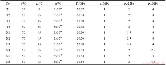
A standard cylinder specimen (D=50 mm, L=100 mm) was adopted (Fig. 1), with an inclined penetrating crack of 2a=30 mm and a=45° and subjected to THM coupling condition (i.e., temperature t, hydraulic pressure pH, confining pressure pM and axial pressure pL). Table 1 shows different THM coupling conditions for calculation, where the axial pressure was unit pressure (pL=1 MPa) and the hydraulic pressure (pH) must be smaller than the confining pressure (pM) in order to avoid the mixture of water and oil. The temperature must be controlled within 100 °C for preventing evaporation of water, since actual temperature in deep mining is lower than 100 °C. Dt, a, and ETwere temperature difference between room temperature and tested temperature, thermal expansion coefficient and elastic modulus, respectively.
2.2 Formula derivation
2.2.1 Stress function
As shown in Fig. 1, a global rectangular coordinate system (XOY) was set at the center of crack surface (O), and a local rectangular (xoy) and a polar (ox) coordinate systems were set at the crack tip (o).
The boundary collocation method was applied to calculating stress intensity factor of the cylinder specimen under THM coupling condition, where a biharmonic stress function must be chosen appropriately to meet all boundary conditions. Generally, the stress function (φ1) is in the form of series expansion only for the crack without applied force on its surface. For the THM coupling specimen with the hydraulic pressure pH (Fig. 1), it is necessary to introduce an additional constant stress function (φ2). The stress function φ is written as the sum of φ1 and φ2.
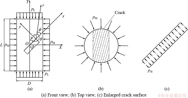
Fig. 1 THM coupling calculation model
Table 1 THM coupling loading condition

 (1)
(1)
 (2)
(2)
 (3)
(3)
where An, Bn, Cn, and Dn are coefficients determined by boundary conditions. Obviously, the stress function φ can satisfy the biharmonic equation  φ=0.
φ=0.
In the polar coordinate system, the stress components are expressed as
 (4)
(4)
Substituting the boundary condition of crack surface (when θ=0, σθ=-pH and τrθ=0) into Eq. (4), it becomes


i.e.,


Therefore, the stress function is simplified as


 (5)
(5)
In order to determine the coefficients An, Bn, Cn, and Dn conveniently, angle Ψ is introduced and positive angle Ψ is defined in anticlockwise direction (Fig. 1(a)). SubstituteΨ=θ-Π into Eq. (5) and then rewrite the stress function φ in the sum of even function φe(r, Ψ) and odd function φo(r, Ψ) for calculating tensile (Mode I) and shear (Mode II) stress intensity factor, respectively.
 (6)
(6)

 (7)
(7)

 (8)
(8)
Since the stress intensity factor at crack tip is calculated when r→0, only the least power term r3/2 in Eqs. (7) and (8) needs to be considered and thus Eq. (6) becomes

 (9)
(9)
The stress components in the polar coordinate system can be obtained by substituting Eq. (9) into Eq. (4)
 (10)
(10)
and the stress components in rectangular coordinate system can be obtained by coordinate transformation.
 (11)
(11)
According to the stress components under mixed mode loading
 (12)
(12)
Modes I and II stress intensity factors KI and KII can be calculated by comparing Eqs. (11) and (12) as follows.
 (13)
(13)
It is seen that KI and KII depend only on the two coefficients a1 and b1. The two coefficients can be determined by boundary conditions, i.e., selecting several points at the boundary except the crack surface (which is included in the stress function φ2) and solving the equations of a1 and b1 established by the boundary condition.
2.2.2 Coefficients for stress function
For different values of m (m=1, 2, …) in Eqs. (6-8), there are different numbers of the coefficients a and b, and different numbers of the boundary points are needed for determining the different coefficients. As shown in Fig. 2, several boundary points Mi and Ni (i=1, 2, …) are selected on the cylindrical generatrix passing through the crack midpoint at interval of 5 mm and their polar coordinates can be calculated by geometrical relations of the triangles (Table 2). Since any boundary point Mi or Ni (i=1, 2, …) has the following stress components in X and Y directions according to THM loading condition:
 (14)
(14)
the coefficients a and b for the stress function can be determined by using stress analysis of the element (Fig. 3) and Eq. (4).
Table 2 Polar coordinate of boundary points
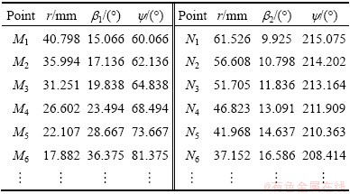
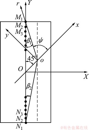
Fig. 2 Boundary points position
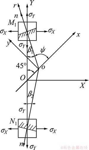
Fig. 3 Polar stress of boundary points
Take the specimen T1 as an example to illustrate the detailed process. Firstly, let m=1 and Eq. (6) becomes

 (15)
(15)
Because the term of b2 always equals zero, there is only three coefficients a1, a2 and b1 and thus two boundary points M1 and M2 are enough, with four known stress conditions (each point has both normal and shear stresses).
The polar normal and shear stresses of M1 and N1 can be calculated by stress analysis.
 (16)
(16)
 (17)
(17)
In addition, the polar stress expressions of points M1 and N1can be obtained by substituting Eq. (15) and the polar coordinates of points M1 and N1 into Eq. (4)
with the consideration of Ψ=θ-Π.
 (18)
(18)
 (19)
(19)
Combining Eqs. (16-19) results in four linear equations including the three coefficients a1, a2 and b1. The overdetermined equations are rewritten in the form of matrix as follows, which can be solved by least square method, i.e., the optimal solution of x must satisfy min ||Ax-b||.
 (20)
(20)

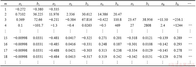
From the above analysis, it is seen that m=1 corresponds to three coefficients and two boundary points. Therefore an arbitrary value of m (m=1, 2, …) corresponds to coefficients of 4m-1 and boundary points of 2m are needed for determining the coefficients of 4m-1 (each point has both normal and shear stresses). Similarly, overdetermined equations of 4m can be obtained and coefficients of 4m-1 can be calculated as listed in Table 3. It is found that the values of a1 and b1 for determining KI and KII (Eq.(13)) are almost unchanged and can be regarded as convergence when m3 15. Therefore, the values of a1 and b1 in the case of m=15 can meet accuracy requirements for calculating KI and KII.
Table 3 Corresponding undetermined coefficients of different m in stress function (Specimen T1)
2.2.3 Stress intensity factor
For the specimen T1 under THM coupling condition, modes I and II stress intensity factors are calculated by substituting the values of a1 and b1 (m=15) into Eq. (13).
 (21)
(21)
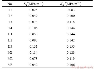
Table 4 lists the stress intensity factors of different specimens with different THM coupling conditions (Table 1). Calculation formulae of THM coupling stress intensity factors can be obtained by fitting method.
 (22)
(22)
Table 4 THM coupling stress intensity factors
3 Test verification
3.1 Test arrangement
Rock material was local red sandstone, and its mineral composition was quartz (90.0%) and little feldspar (4.1%) cemented by hydromica (4.8%) and kaolinite (1.1%), etc. Rock specimen was the same as the calculation model (Fig. 1), i.e., standard cylinder of d50 mm×100 mm with a penetrating precrack of 2a=30 mm and a=45°. An additional vertical hole of d3 mm×50 mm was drilled from the bottom center of the specimen to the crack surface in order to apply the hydraulic pressure PH on the crack surface (Fig. 4).
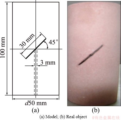
Fig. 4 Rock specimen
THM coupling fracture test was conducted by the self-designed THM coupling testing system (Fig. 5), including tri-axial loading system, hydraulic pressure and confining pressure loading system. The hydraulic pressure and confining pressure system were connected to the tri-axial loading system by high-strength hose, in which special isolation films were used to avoid the water mixing with the oil. Before the test, both the rock specimen and the water were heated to the specific temperature t. The temperature t must be controlled within 100 °C for preventing evaporation of water since actual temperature in deep mining is lower than 100 °C and the hydraulic pressure pH must be smaller than the confining pressure pM in order to prevent the water mixing with oil, as shown in Table 1. During the test, the maximum axial pressure pL,max was recorded for calculating the maximum stress intensity factors KI,max and KII,max (Eq. (22)) and microscopic characteristics of the fractured specimens were analyzed by a scanning electron microscope for revealing the fracture mechanism.

Fig. 5 THM coupling testing system
3.2 Test results and analysis
3.2.1 Fracture mode
In classical fracture mechanics, fracture mode (Mode I or Mode II) is assumed to be the same as loading forms (tension or shear). That is suitable for most metal materials. For brittle rock with much smaller tensile strength than shear strength, the shear loading results in the tensile fracture rather than the shear fracture. Therefore, a new fracture criterion of stress intensity factor ratio has been established based on the fact that the fracture mode ( Mode I, II or mixed mode) depends on the ratio of maximum shear to tensile stress intensity factor at crack tip (KII,max/KI,max) but not the loading mode as follows [15].
 (23)
(23)
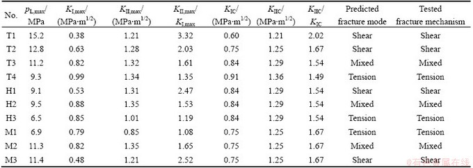
In the new fracture criterion, the maximum modes I and II stress intensity factors (KI,max and KII,max) of the THM coupling specimens are calculated by substituting the tested value of maximum axial pressure pL,max (Table 5) into Eq. (22). Modes I and II fracture toughness (KIC and KIIC) of the red sandstone were obtained by three-points bending test and shear-box test at different
temperatures t (Table 5), since KIC and KIIC (as a material constant) are independent of the hydraulic pressure pH, confining pressure pM and axial pressure pL, but affected by temperature t. Thus the fracture modes of the THM coupling specimens can be predicted (Table 5) according to the new fracture criterion (Eq. (23)).
3.2.2 Fracture trajectory and fracture mechanism
Figures 6-11 show the fracture trajectories and SEM images of the THM coupling specimens, and the microscopic fracture mechanism is analyzed as follows.
1) Under lower temperatures (Specimens T1, T2), lower hydraulic pressure (Specimen H1) and higher confining pressure (Specimen M3), the specimens have similar macroscopic and microscopic fracture characteristics (Figs. 6(a), 6(b), 7(a) and 8(d)). The cracks are initiated at the two crack tips and propagated only in one direction of negative angle (y<0 clockwise, Fig. 1(a)). There are many sliding steps and dense parallel stripes appearing on the fractured surfaces and transgranular fracture occurs, which are typical characteristics of Mode II (shear) fracture.
2) Under higher temperature (Specimen T4), higher hydraulic pressure (Specimen H3) and lower confining pressure (Specimen M1), the specimens have similar macroscopic and microscopic fracture characteristics (Figs. 6(d), 7(d) and 8(a)). The cracks are initiated at the two crack tips and propagated only in one direction of positive angle (y>0 anticlockwise, Fig. 1(a)). There are many complete crystal particles in sugar shape appearing on the fractured surfaces and intergranular fracture occurs, which are typical characteristics of Mode I (tensile) fracture.
Table 5 THM coupling fracture mode and mechanism of red sandstone specimens
3) Under middle temperature (Specimen T3), middle hydraulic pressure (Specimen H2) and middle confining pressure (Specimen M2), the specimens have similar macroscopic and microscopic fracture characteristics (Figs. 6(c), 7(c) and 8(b)). The cracks are initiated at the two crack tips and propagated in two directions (y<0 clockwise and y>0 anticlockwise, Fig. 1(a)). Both the sliding steps of parallel stripes and the complete crystal particles in sugar shape appear on the fractured surfaces, and both the transgranular and intergranular fractures occur, which are typical characteristics of mixed mode fracture.
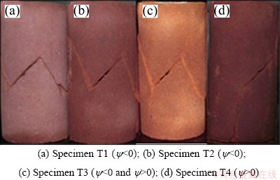
Fig. 6 Fracture trajectories of red sandstone at different temperatures
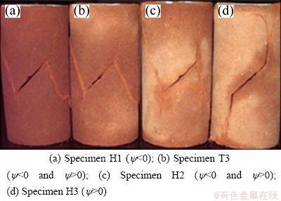
Fig. 7 Fracture trajectories of red sandstone at different hydraulic pressures
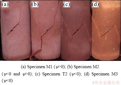
Fig. 8 Fracture trajectories of red sandstone at different confining pressures
Table 5 lists the test results of fracture mechanisms of the THM coupling specimens based on the fracture trajectories and microscopic characteristics, which are in good agreement with the predicted results of fracture modes based on Eqs. (22) and (23). It is verified that the established calculation formula of stress intensity factor (Eq. (22)) is correct for the THM coupling specimen.
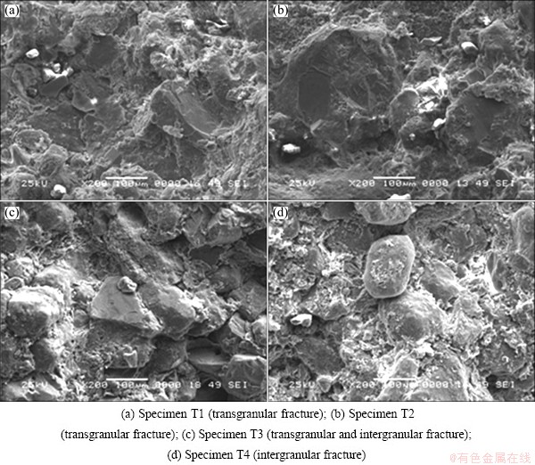
Fig. 9 Fracture morphologies of red sandstone at different temperatures
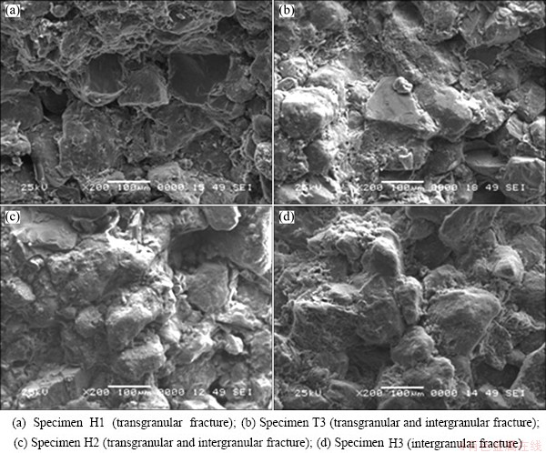
Fig. 10 Fracture morphologies of red sandstone at different hydraulic pressures
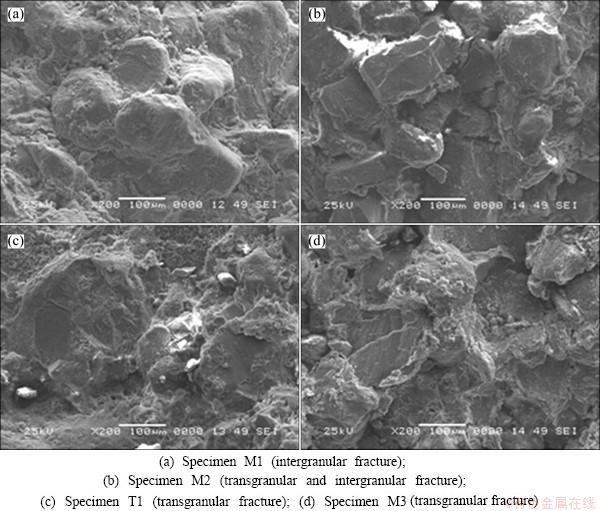
Fig. 11 Fracture morphologies of red sandstone at different confining pressures
4 Conclusions
1) Traditional boundary collocation method is only suitable for calculating stress intensity factor of the cracked specimen without any force on its crack surface. By successfully introducing an additional constant stress function into the boundary collocation method, a calculation formula of THM coupling stress intensity factor of the cracked specimen (with hydraulic pressure applied on its crack surface) was firstly derived, which is very important both for improving classical fracture mechanics theory and for providing evidence for fracture prediction, safety assessment and cracking-arrest design in THM coupling rock engineering.
2) The maximum THM coupling stress intensity factors can be determined by substituting the maximum axial load measured by self-designed THM coupling fracture test into the newly-derived THM coupling stress intensity factor formula. THM coupling fracture modes (including tensile, shear and mixed fracture mode) can be predicted based on a new fracture criterion of stress intensity factor ratio.
3) SEM analyses of THM coupling fractured surface indicated that the higher the temperature and hydraulic pressure are and the lower the confining pressure is, the more easily the intergranular (tension) fracture occurs. The transgranular (shear) fracture occurs in the opposite case and the mixed-mode fracture occurs in the middle case. The tested THM coupling fracture mechanisms are in good agreement with the predicted THM coupling fracture modes, which can verify correction of the newly-derived THM coupling stress intensity factor formula.
References
[1] JING L, TSANG C F, STEPHANSSON O. DECOVLALEX―An international co-operative research project on mathematical models of coupled THM processes for safety analysis of radioactive waste Repositories [J]. International Journal of Rock Mechanics and Mining Sciences, 1995, 32(5): 389-398.
[2] HUDSON J A, STEPHANSSON O, ANDERSSON J, TSANG C F, JING L. Coupled T-H-M issues relating to radioactive waste repository design and performance [J]. International Journal of Rock Mechanics and Mining Sciences, 2001, 38(1): 143-161.
[3] RUTQVIST J, CHIJIMATSU M, JING L, MILLARD A, NGUYEN T S, REJEB A, SUGITA Y, TSANG C F. A numerical study of THM effects on the near-field safety of a hypothetical nuclear waste repository-BMT1 of the DECOVALEX III project. Part 3: Effects of THM coupling in sparsely fractured rocks [J]. International Journal of Rock Mechanics and Mining Sciences, 2005, 42(5-6): 745-755.
[4] XIE Hai-feng, RAO Qiu-hua, XIE Qiang, LI Zong-yu, WANG Zhi. Plane shear (Mode II) fracture experiment analysis of brittle rock at high temperature [J]. The Chinese Journal of Nonferrous Metals, 2008, 15(s1): 402-405. (in Chinese)
[5] CHAN T, KHAIR K, JING L, AHOLA M, NOORISHAD J, VUILLOD E. International comparison of coupled thermo-hydro- mechanical models of a multiple-fracture bench mark problem: DECOVALEX phase I, bench mark test 2 [J]. International Journal of Rock Mechanics and Mining Sciences & Geomechanics Abstracts, 1995, 32(5): 435-452.
[6] SHAHANI A R, NABAVI S M. Closed form stress intensity factors for a semi-elliptical crackin a thick-walled cylinder under thermal stress [J]. International Journal of Fatigue, 2006, 28(8): 926-933.
[7] NABAVI S M, GHAJAR R. Analysis of thermal stress intensity factors for cracked cylindersusing weight function method [J]. International Journal of Engineering Science, 2010, 48(12): 1811-1823.
[8] JOHNSON J, QU J. An interaction integral method for computing mixed modestress intensity factors for curved bimaterial interface cracksin non-uniform temperature fields [J]. Engineering Fracture Mechanics, 2007, 74(14): 2282-2291.
[9] LIU Jun-yu, LIN Gao. Effect of the water pressure inside the crack on the fracture behavior of concrete gravity dam [D]. Dalian: Dalian University of Technology, 2008. (in Chinese)
[10] YEW C H, LIU G F. The fracture tip and critical stress intensity factor of a hydraulically induced fracture [J]. SPE Production and Facilities, 1993, 8(3): 171-177.
[11] LI Xi-bing, HE Xian-qun, CHEN Hong-jiang. Crack initiation characteristics of opening-mode crack embedded in rock-like material under seepage pressure [J]. Chinese Journal of Rock Mechanics and Engineering, 2012, 31(7): 1317-1324. (in Chinese)
[12] ZHAO Yan-lin, CAO Ping, WEN You-dao, YANG Hui, LI Jiang-teng. Damage fracture failure mechanism of compressive-shear rock cracks under seepage pressure [J]. Journal of Central South University: Science and Technology, 2008, 39(4): 838-844. (in Chinese)
[13] HUANG K, GHASSEMI A. Modeling 3d hydraulic fracture propagation and thermal fracture using virtual multidimensional internal bonds [J]. Geothermal Reservoir Engineering, 2012, 18(1): 311-320.
[14] MOHAMMADREZA J. Thermo-hydro-mechanical behavior of conductive fractures using a hybrid finite difference-displacement discontinuity method [D]. Waterloo: University of Waterloo, 2013.
[15] RAO Q H, SUN Z Q, STEPHANSSON O, LI C L, STILLBORG B. Shear fracture (Mode II) of brittle rock [J]. International Journal of Rock Mechanics and Mining Sciences. 2003, 40(3): 355-375.
脆性岩石热-水-力耦合应力强度因子计算
李 鹏1,饶秋华1,李 卓1,敬 静2
1. 中南大学 土木工程学院,长沙 410075;
2. 中南大学 资源与安全工程学院,长沙 410083
摘 要:采用边界配置法并引入附加的常应力函数,成功地推导出岩石热-水-力(THM)耦合条件下含裂纹试件(裂纹面有水压作用)的裂尖应力强度因子计算公式。利用自行设计的THM耦合断裂试验,测定脆性岩石THM耦合断裂的最大轴压,并依据新推导的公式和新型应力强度因子比断裂准则预测脆性岩石THM耦合断裂模式。岩石THM耦合断口的形貌特征分析结果表明:温度、水压越高,围压越低,沿晶(拉伸)断裂越容易发生;反之,则穿晶(剪切)断裂更容易发生;而介于两者中间时,则复合型断裂更容易发生。测得的THM耦合断裂机理与预测的THM耦合断裂模式结论一致,从而验证了推导出的THM耦合应力强度因子计算公式的正确性。
关键词:应力强度因子;热-水-力耦合; 边界配置法;断裂机理;脆性岩石
(Edited by Sai-qian YUAN)
Foundation item: Project (11072269) supported by the National Natural Science Foundation of China; Project (20090162110066) supported by the Research Fund for the Doctoral Program of Higher Education of China
Corresponding author: Qiu-hua RAO; Tel: +86-731-88836423; E-mail: raoqh@csu.edu.cn
DOI: 10.1016/S1003-6326(14)63088-0

