
Influences of stoichiometric ratio B/A on structures and electrochemical behaviors of La0.75Mg0.25Ni3.5Mx(M=Ni, Co; x=0-0.6) hydrogen storage alloys
ZHANG Yang-huan(张羊换)1, 2, DONG Xiao-ping(董小平)1, 3, ZHAO Dong-liang(赵栋梁)1,
GUO Shi-hai(郭世海)1, QI Yan(祁 焱)1, WANG Xin-lin(王新林)1
1. Department of Functional Materials Research, Central Iron and Steel Research Institute, Beijing 100081, China;
2. School of Materials, Inner Mongolia University of Science and Technology, Baotou 014010, China;
3. School of Materials Science and Engineering, University of Science and Technology Beijing,
Beijing 100083, China
Received 24 September 2007; accepted 7 January 2008
Abstract: In order to investigate the influences of the stoichiometric ratio of B/A (A: gross A-site elements, B: gross B-site elements) and the substitution of Co for Ni on the structures and electrochemical performances of the AB3.5-4.1-type electrode alloys, the La-Mg-Ni-Co system La0.75Mg0.25Ni3.5Mx (M=Ni, Co; x= 0, 0.2, 0.4, 0.6) alloys were prepared by induction melting in a helium atmosphere. The structures and electrochemical performances of the alloys were systemically measured. The results show that the structures and electrochemical performances of the alloys are closely relevant to the B/A ratio. All the alloys exhibit a multiphase structure, including two major phases, (La, Mg)2Ni7 and LaNi5, and a residual phase LaNi2, and with rising ratio B/A, the (La,Mg)2Ni7 phase decreases and the LaNi5 phase increases significantly. When ratio B/A=3.7, the alloys obtain the maximum discharge capacities. The high rate discharge(HRD) capability of the alloy (M=Ni) monotonously rises with growing B/A ratio, but that of the alloy (M=Co) first mounts up then declines. The cycle stability of the alloy (M=Co) monotonously increases with rising B/A ratio, but it first decreases slightly then increases for the alloy (M=Ni). The discharge potential of the alloy (M=Ni) declines with increasing B/A ratio (x>0.2), but for the alloy (M=Co), the result is contrary. The substitution of Co for Ni significantly ameliorates the electrochemical performances. For a fixed ratio B/A=3.7, the Co substitution enhances the discharge capacity from 365.7 to 401.8 mA?h/g, the capacity retention ratio (S100) after 100 charging-discharging cycles from 50.32% to 53.26% and the HRD from 88.65% to 90.69%.
Key words: stoichiometric ratio; La-Mg-Ni-Co alloy; hydrogen storage alloy; substitution; Co; Ni
1 Introduction
Recently, R-Mg-Ni-based (where R is a rare earth or Y, Ca) PuNi3-type alloys have been considered to be the most promising candidate owing to their high discharge capacities (360-410 mA?h/g) and low production costs in spite of their poor cycle stabilities. A lot of investigations on this kind of alloys have been performed in the world, and some very important results have been obtained. LIU et al[1] revealed that the La0.7Mg0.3(Ni0.85Co0.15)3.5 alloy had a multi-phases structure, and two major phases were found, e.g. a (La, Mg)Ni3 phase with the PuNi3-type rhombohedral structure in space group m and a LaNi5 phase with the CaCu5-type hexagonal structure in space group P6/mmm. KOHNO et al[2] found that the La5Mg2Ni23-type electrode alloy La0.7Mg0.3Ni2.8Co0.5 had a capacity of 410 mA?h/g, and good cycle stability during 30 charge-discharge cycles. PAN et al[3] investigated the structures and electrochemical characteristics of the La0.7Mg0.3(Ni0.85Co0.15)x (x=3.15-3.80) alloy system and obtained a maximum discharge capacity of 398.4 mA?h/g, but the cycle stability of the alloy needs to be further improved. After investigating the structure and the electrochemical performances of the La0.67Mg0.33Ni3.0-x- Cox (x=0-0.75) alloys, WANG et al[4] reported that the alloy (x=0.5) obtained a maximum discharge capacity of 404.47 mA?h/g, and the addition of Co significantly improved the cycle stability of the alloys. A systemic investigation on the influence of the stoichiometric ratio B/A on the structure and electrochemical performances of the AB3.5-4.1-type electrode alloys will be helpful to the development of the La-Mg-Ni system electrode alloys. Therefore, in this work, the structures and electro- chemical characteristics of the La0.75Mg0.25Ni3.5Mx (M=Ni, Co; x=0-0.6) hydrogen storage alloys were investigated, and the stoichiometric ratio B/A at which the La-Mg-Ni system electrode alloy has good integrated electrochemical performances is selected.
2 Experimental
The nominal compositions of the experimental alloys were La0.75Mg0.25Ni3.5Mx (M=Ni, Co; x=0, 0.2, 0.4, 0.6). The purity of all the component metals (La, Ni, Co, Mg) was at least 99.8%. The experimental alloys were melted in a vacuum induction furnace at a high purity helium atmosphere with a pressure of 0.04 MPa for preventing the volatilization of magnesium during the melting. A cast ingot was thus obtained by pouring the melt into a copper mould cooled by water.
The alloys were mechanically crushed and ground into the powder of <50 μm size for X-ray diffraction (XRD). The phase structures and compositions of the alloys were determined by X-ray diffractometer (D/max/ 2400). The diffraction, with the experimental parameters of 160 mA, 40 kV and 10(?)/min respectively, was performed with Cu Kα1 radiation filtered by graphite. The samples prepared by direct polish were etched with a 60% HF solution, and the morphologies of the alloys were examined by SEM.
Round electrode pellets with a diameter of 15 mm were prepared by cold pressing a mixture of 0.2 g alloy powder and carbonyl nickel powder in a mass ratio of 1?4 under a pressure of 35 MPa for 5 min. After being dried for 4 h, the electrode pellets were immersed in a 6 mol/L KOH+15 g/L LiOH solution for 24 h in order to have fully wet electrodes before the electrochemical measurement.
A tri-electrode open cell, consisting of a metal hydride electrode, a NiOOH/Ni(OH)2 counter electrode and a Hg/HgO reference electrode, was used for testing the electrochemical performances of the experimental electrodes. The electrolyte was a 6 mol/L KOH+15 g/L LiOH solution. The voltage between the negative electrode and the reference electrode was defined as the discharge voltage. In every cycle, the alloy electrode was charged with a constant current density. After resting for 15 min, it was discharged at the same current density to -0.500 V cut-off voltage.
After the alloy electrodes were completely activated, the electrochemical impedance spectroscopy(EIS) of the alloys were measured by an advanced electrochemical system PARSTAT 2273 at 50% depth of discharge(DOD) and in the frequency range from 10 kHz to 5 MHz with an amplitude of 5 mV under the open-circuit condition. The environment temperature of the measurement was kept at 30 ℃.
3 Results and discussion
3.1 Structural characteristics
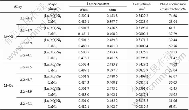
The XRD patterns of the La0.75Mg0.25Ni3.5Mx (M= Ni, Co; x=0-0.6) alloys are shown in Fig.1. All the alloys hold a multiphase structure, consisting of (La, Mg)2Ni7 and LaNi5 major phases as well as LaNi2 residual phase. The lattice parameters and the phase abundances of two major phases LaNi5 and (La, Mg)2Ni7 in the alloys, which were calculated from the XRD data by the software Jade 6.0, are listed in Table 1. The results indicate that the lattice constants and abundances of the alloys have significant changes with the variety of the B/A ratio. It can be clearly seen that both the parameter a and the unit cell volume of the (La,Mg)2Ni7 and the LaNi5 phases decrease with increasing B/A ratio. However, the parameter c of the (La,Mg)2Ni7 phase decreases and that of the LaNi5 phase increases with increasing B/A ratio. The abundance of the (La,Mg)2Ni7 phase reduces and that of the LaNi5 phase increases with rising B/A ratio. When B/A ratio increases from 3.5 to 4.1, the abundance of the (La,Mg)2Ni7 phase drops from 74.68% to 28.53%, and that of the LaNi5 phase mounts up from 23.04% to 71.42% for the alloy (M=Ni), and from 74.68% to 31.06% and from 23.04% to 68.91% for the alloy (M=Co), respectively. The substitution of Co for Ni increases the abundance of the (La,Mg)2Ni7 phase but decreases that of the LaNi5 phase, and it enlarges the lattice parameters and the cell volume of the major phases in the alloy.
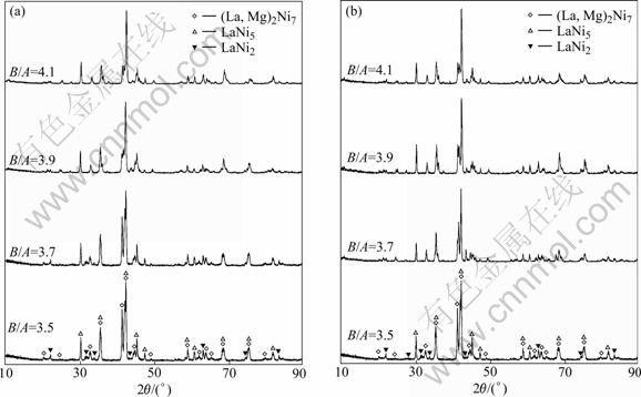
Fig.1 XRD patterns of La0.75Mg0.25Ni3.5Mx (M=Ni, Co; x=0-0.6) alloys: (a) M=Ni; (b) M=Co
Table 1 Lattice parameters and abundances of LaNi5 and (La,Mg)Ni3 phases
The SEM images of the La0.75Mg0.25Ni3.5Mx (M=Ni, Co; x=0-0.6) alloys are shown in Fig.2. The result obtained by energy dispersive spectrometry(EDS) (Fig.3) indicates that the experimental alloys are of multiphase structure, containing (La,Mg)2Ni7 (denoted by A) and LaNi5 (denoted by B) phases, which is in agreement with the results analyzed by XRD. Because the amount of the LaNi2 phase in the alloys is small and it attaches itself to the (La, Mg)2Ni7 phase in the process of growing, it is difficult to observe the morphology of the LaNi2 phase. It is also seen in Fig.2 that the amount of the LaNi5 phase significantly increases with increasing B/A ratio.
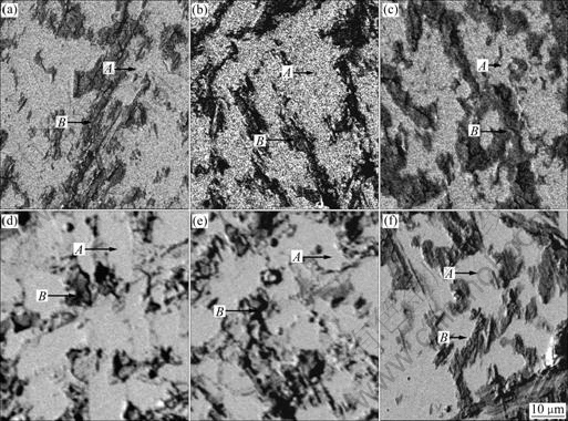
Fig.2 SEM images of La0.75Mg0.25Ni3.5Mx alloys: (a), (b) and (c) M = Ni, x=0.2, 0.4 and 0.6; (d), (e) and (f) M=Co, x=0.2, 0.4 and 0.6, respectively
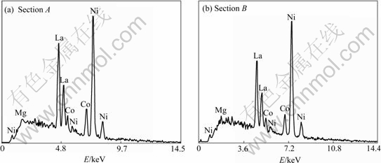
Fig.3 Typical EDS spectra of sections A and B in Fig.2(d)
3.2 Electrochemical performances
3.2.1 Discharge potential characteristic and discharge capacity
The discharge performances are characterized by the potential plateau of the discharge curve of the alloy. The longer and the more horizontal the potential plateau, the better the potential characteristics of the alloy. The discharge potential curves of the La0.75Mg0.25Ni3.5Mx (M=Ni, Co; x=0-0.6) alloys are presented in Fig.4. It is shown that the variety of B/A ratio exerts a significantly impact on the discharge potential characteristics of the alloys. For the alloy (M= Ni), the discharge potential of the alloy (B/A≤3.7) rises with increasing B/A ratio, but the increase of B/A ratio (B/A>3.7) leads to the decrease of the discharge potential of the alloy; and for the alloy (M=Co), the discharge potential of the alloy rises with the increase of B/A ratio. The plateau potential is closely relative to the internal resistance of the battery, including ohmic internal resistance and polarization resistance. The discharge reaction of the alloy electrode mainly depends on the diffusion of hydrogen atoms in the alloy, and the internal resistance of the alloy electrode reduces with the increase of the diffusion coefficient of the hydrogen atom[5]. A proper ratio of (La,Mg)2Ni7 to LaNi5 phases is probably the reason why the alloy (B/A=3.7) has a high discharge potential.
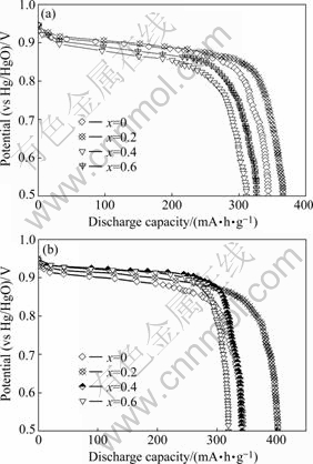
Fig.4 Discharge potential curves of La0.75Mg0.25Ni3.5Mx alloys: (a) M=Ni; (b) M=Co
The maximum discharge capacities of the La0.75Mg0.25Ni3.5Mx (M=Ni, Co; x=00.6) alloys as a function of B/A ratio are shown in Fig.5, at charge- discharge current density being 60 mA/g. It can be derived from Fig.5 that the discharge capacity increases from 343.7 (x=0) to 365.7 mA?h/g (x=0.2), and then drops to 311.2 mA?h/g (x=0.6) for the alloys (M=Ni); and for the alloys (M=Co), it mounts up from 343.7 (x=0) to 401.8 mA?h/g (x=0.2), and then declines to 319.2 mA?h/g (x=0.6). It is also seen in Fig.5 that for a fixed B/A ratio, the substitution of Co for Ni significantly enhances the discharge capacity of the alloy. The maximum discharge capacities of the alloys first increase and then decrease with increasing B/A ratio and the alloys obtain their maximum discharge capacities when ratio B/A=3.7, which is relevant to the change of the phase abundances of the alloys caused by the variety of B/A ratio. The LaNi5 phase in the alloy increases with rising B/A ratio (Fig.1), which is disadvantageous to the discharge capacity of the alloy due to the fact that the discharge capacity of the LaNi5 phase is less than that of the (La,Mg)Ni3 phase[6-7]. However, it is noteworthy that the LaNi5 phase works not only as a hydrogen reservoir but also as a catalyst to activate the (La,Mg)2Ni7 phase to absorb/desorb reversibly hydrogen in the alkaline electrolyte[8-9]. It is the above contrary effect that results in an optimum B/A ratio for the discharge capacity of the alloy. The fact that Co substitution raises the discharge capacity of the alloys is mainly attributed to the increase of the cell volumes of the alloy caused by the substitution.
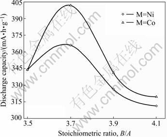
Fig.5 B/A ratio dependence of discharge capacities of La0.75Mg0.25Ni3.5Mx alloys
3.2.2 High rate discharge(HRD) capability
The high rate discharge(HRD) capability, a kinetic property of the alloy electrode, is calculated according to the following formula:
 (1)
(1)
where C600 is the discharge capacity at a discharge current density of 600 mA/g at the cut-off potential of -0.500 V (vs Hg/HgO reference electrode), C60 is the residual discharge capacity at a discharge current density of 60 mA/g also at the cut-off potential of -0.500 V (vs Hg/HgO reference electrode) after the alloy electrode has been fully activated at a discharge current density of 60 mA/g. The HRD capabilities of the La0.75Mg0.25Ni3.5Mx (M=Ni, Co; x=0-0.6) alloys as a function of B/A ratio are shown in Fig.6. It can be derived from Fig.6 that when B/A ratio increases from 3.5 to 4.1, the HRD capability grows from 82.6% (B/A=3.5) to 89.97% (B/A=4.1) for the alloy (M=Ni), and it mounts up from 82.6% (B/A=3.5) to 90.69% (B/A=3.7), and then drops to 78.74% (B/A=4.1) for alloy (M=Co). The HRD capability of the alloy (M=Ni) monotonously rises with growing B/A ratio, for which the increase of the LaNi5 phase is mainly respon- sible because the LaNi5 phase has a good electrocatalytic activity. The substitution of Co for Ni enhances the HRD capability of the alloy (B/A≤3.7), which may be ascribed to the fact that the moderate substitution of Ni by Co can cause the concentration of Co and Ni at the surface of the alloy particles during charge/discharge cycling and the formation of Raney Ni-Co film with higher electrocatalytic activity[10-11]. However, with the further increase of B/A ratio, the substitution of Co for Ni leads to a slight decrease of the HRD capability of the alloy, which can be attributed to the decrease in effective surface area as a result of the decreased volume expansion[12] and the decrease in electrocatalytic activity because of the notable reduction of the Ni content due to the increase of Co substitution.

Fig.6 B/A ratio dependence of high rate discharge capabilities (HRDs) of La0.75Mg0.25Ni3.5Mx alloys
The electrochemical impedance spectra(EIS) were measured in the KOH electrolyte at 303 K. Fig.7 shows the typical electrochemical impedance spectra(EIS) of the La0.75Mg0.25Ni3.5Mx (M=Ni, Co; x=0-0.6) alloy electrodes at 50% depth of discharge(DOD) and 303 K, displaying that the EIS of all the alloys consist of two semicircles. The larger semicircle in the low-frequency region in the spectra can be characterized as the reaction resistance in the charge-transfer process[13]. As shown in Fig.7, the radius of the larger semicircle in the low-frequency region reduces with increasing B/A ratio for the alloy (M=Ni), but it first reduces and then enlarges when Co content x increases from 0 to 0.6, suggesting that the increase of Ni content decreases the charge-transfer reaction resistance of the alloy electrode, but the increase of Co content leads to the charge-transfer reaction resistance to first decrease and then increase, which is in good agreement with the HRD capabilities of the alloys.
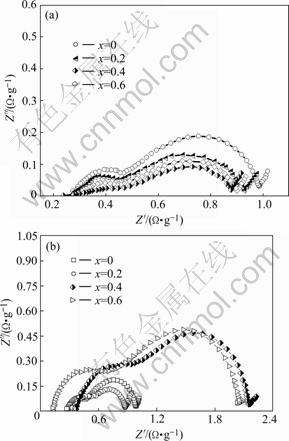
Fig.7 Electrochemical impedance spectra of La0.75Mg0.25Ni3.5- Mx alloy electrodes measured at 50% depth of discharge and 303 K: (a) M=Ni, (b) M=Co
3.2.3 Cycle stability
The cycle stability of the alloys, characterized by the capacity retaining rate (S100), is defined as S100= (C100/Cmax)×100%, where Cmax is the maximum discharge capacity, and C100 is the discharge capacity of the 100th cycle at a current density of 600 mA/g, respectively. The B/A ratio dependence of the capacity retaining rate (S100) of the La0.75Mg0.25Ni3.5Mx (M=Ni, Co; x=0-0.6) alloys is plotted in Fig.8. The figure shows that when B/A ratio rises from 3.5 to 4.1, the capacity retaining rate (S100) drops from 51.5% (B/A=3.5) to 50.32% (B/A=3.7) and then mounts up to 55.53% (B/A= 4.1) for the alloy (M=Ni), and it enhances from 51.5% (B/A=3.5) to 60.09% (B/A=4.1) for the alloy (M=Co). It can be clearly seen in Fig.8 that for a fixed B/A ratio, the Co substitution raises the capacity retaining rate (S100) of the alloy.
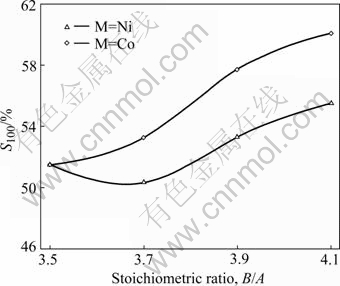
Fig.8 B/A ratio dependence of capacity retaining rate (S100) of alloys
In order to understand correctly the mechanism of the efficacy loss of the experimental alloy electrode, the morphologies of the alloy particles before and after electrochemical cycle observed by SEM are shown in Fig.9. The cracks on the surface of the alloy particles after electrochemical cycle can clearly be seen in Fig.9(b), confirming that the pulverization of alloy particles takes place in the process of charging- discharging cycle, but the pulverization degree of the alloy is much smaller than that of the AB5-type alloy[14].
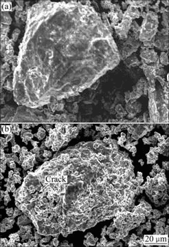
Fig.9 SEM morphologies of alloy (x=0) before (a) and after (b) electrochemical cycle
It is noteworthy that a rough and porous layer can clearly be found on the surface of the alloy particles after electrochemical cycle.
In order to confirm the presence of the oxidation layer on the surface of the alloy electrode, the core level spectra of La 3d and Mg 2p orbital electrons in the alloy (x=0) before and after electrochemical cycling are analyzed, as shown in Fig.10. The deviation of these peaks caused by the charge effect is corrected by binding energy (284.6 eV) for C 1s, using a software of XPSEAK, obtaining the binding energies of La 3d and Mg 2p orbital electrons. The level binding energies of La 3d and Mg 2p orbital electrons are 835.90 and 49.8 eV, respectively, showing that the electrochemical cycle leads to an obvious change of the binding energies of La 3d and Mg 2p orbital electrons. The binding energy of Mg 2p from energy spectra before cycling exceeds that of metallic Mg (49.8 eV), which is ascribed to the oxidization of Mg owing to its contacting with air, as shown in the Fig.10(a). Therefore, it can be concluded that the reason why electrochemical cycle causes a change of the binding energies of the alloy electrons is that La and Mg in the alloy are oxidized to form La2O3 and MgO because La and Mg directly contact with the
alkaline electrolyte during electrochemical cycle. It is the oxidation-passivation layer, decreasing the electronic conductibility of the surface of the alloy electrode, preventing the diffusion of hydrogen atoms, reducing charge-transfer in the process of electrochemical reaction, that lessens the capability of hydrogen absorption/ desorption of the alloy.

Fig.10 Core level spectra of La 3d and Mg 2p orbital electrons in alloy (x=0) before and after electrochemical cycle
The positive impact of the Co substitution on the cycle stability is ascribed to the increase of the cell volume and the decrease of the expansion/contraction ratio of the alloy in the process of the hydrogen absorption/desorption, which means strengthening the anti-pulverization capability of the alloy.
4 Conclusions
1) The La-Mg-Ni-Co system La0.75Mg0.25Ni3.5Mx (M=Ni, Co; x= 0, 0.2, 0.4, 0.6) hydrogen storage alloys have a multi-phase structure, involving the (La,Mg)2Ni7 and LaNi5 major phases as well as the LaNi2 residual phase. When B/A ratio increases from 3.5 to 4.1, the content of (La,Mg)2Ni7 phase reduces from 74.68% to 28.53%, and that of the LaNi5 phase grows from 23.04% to 71.42% for the alloy (M=Ni), and from 74.68% to 31.06% and from 23.04% to 68.91% for the alloy (M= Co), respectively.
2) The discharge capacities of the alloys have a maximum value with the variety of B/A ratio. The HRD capability of the alloy (M=Ni) monotonously rises with growing B/A ratio, but the HRD capability of the alloy (M=Co) first rises and then drops. The capacity retaining rates (S100) of the alloy (M=Ni) first decrease then increase with the incremental change of B/A ratio, whereas the rates of the alloy (M=Co) monotonously increase.
3) The substitution of Co for Ni significantly affects the electrochemical performances of the alloys: enhancing the discharge capacity and the cycle stability, improving the discharge potential characteristic, increasing the high rate discharge (HRD) ability of the alloys (B/A≤3.7).
4) When the stoichiometric ratio B/A is 3.7, the alloys exhibit good integrative electrochemical performances: the discharge capacity of 343.7 mA?h/g, the high rate discharge(HRD) ability of 88.65%, the capacity retaining rate (S100) of 50.32% for the alloy (M=Ni), and 401.8 mA?h/g, 90.69% and 53.26% for the alloy (M=Co), respectively.
References
[1] LIU Y F, PAN H G, GAO M X, LEI Y Q, WANG Q D. XRD study on the electrochemical hydriding/dehydriding behavior of the La-Mg-Ni-Co-type hydrogen storage alloys [J]. J Alloys Comp, 2005, 403: 296-304.
[2] KOHNO T, YOSHIDA H, KAWASHIMA F, INABA T, SAKAI I, YAMAMOTO M, KANDA M. Hydrogen storage properties of new ternary system alloys: La2MgNi9, La5Mg2Ni23, La3MgNi14 [J]. J Alloys Comp, 2000, 311: L5-L7.
[3] PAN H G, LIU Y F, GAO M X, ZHU Y F, LEI Y Q, WANG Q D. An investigation on the structural and electrochemical properties of La0.7Mg0.3(Ni0.85Co0.15)x (x=3.15-3.80) hydrogen storage electrode alloys [J]. J Alloys Comp, 2003, 351: 228-234.
[4] WANG D H, LUO Y C, YAN R X, ZHANG F L, KANG L. Phase structure and electrochemical properties of La0.67Mg0.33Ni3.0-xCox (x=0, 0.25, 0.5, 0.75) hydrogen storage alloys [J]. J Alloys Comp, 2006, 413: 193-197.
[5] LAI W H, YU C Z. Research survey of improving discharge voltage platform for Ni-MH battery [J]. Chinese Battery, 1996, 26(4): 189-191. (in Chinese)
[6] LIU Y F, PAN H G, GAO M X, ZHU Y F, LEI Y Q. Hydrogen storage and electrochemical properties of the La0.7Mg0.3Ni3.825-x- Co0.675Mnx hydrogen storage electrode alloys [J]. J Alloys Comp, 2004, 365: 246-252.
[7] TAKESHITA T, WALLACE W E, CRAIG R S. Hydrogen solubility in 1:5 compounds between yttrium or thorium and nickel or cobalt [J]. Inorg Chem, 1974, 13: 2282-2283.
[8] PAN H G, LIU Y F, GAO M X, LEI Y Q, WANG Q D. A study of the structural and electrochemical properties of La0.7Mg0.3- (Ni0.85Co0.15)x (x=2.5-5.0) hydrogen storage alloys [J]. J Electrochem Soc, 2003, 150(5): A565-A570.
[9] LIU Y F, PAN H G, GAO M X, ZHU Y F, GE H W, LI S Q, LEI Y Q. Investigation on the structure and electrochemical properties of the rare-earth Mg-based hydrogen storage electrode alloys [J]. Acta Metallurgica Sinica, 2003, 39(6): 666-672. (in Chinese)
[10] FIORINO M E, OPILA R L, KONSTADINIDAS K, FANG W C. Electrochemical and X-ray photoelectron spectroscopy characterization of surface films on MmNi3.5Al0.8Co0.7 [J]. J Electrochem Soc, 1996, 143: 2422-2428.
[11] IWAKURA C, FUKUDA K, SENOH H, INOUE H, MATSUOKA M, YAMAMOTO Y. Electrochemical characterization of MmNi4.0-xMn0.75Al0.25Cox electrodes as a function of cobalt content [J]. Electrochim Acta, 1998, 43: 2041-2046.
[12] CHOQUETTE Y, MENARD H, BROSSARD L. Electrocatalytic performance of composite-coated electrodes for alkaline water electrolysis [J]. Int J Hydrogen Energy, 1990, 15: 21-26.
[13] KURIYAMA N, SAKAI T, MIYAMURA H, UEHARA I, ISHIKAWA H, IWASAKI T. Electrochemical impedance and deterioration behavior of metal hydride electrodes [J]. J Alloys Comp, 1993, 202: 183-197.
[14] ZHANG Y H, WANG G Q, DONG X P, GUO S H, REN J Y, WANG X L. Effect of substituting Co with Fe on the cycle stabilities of the as-cast and quenched AB5-type hydrogen storage alloys [J]. J Power Sources, 2005, 148: 105-111.
Foundation item: Project(2006AA05Z132) supported by High-tech Research and Development Program of China; Project(50642033) supported by the National Natural Science Foundation of China; Project(200711020703) supported by the Natural Science Foundation of Inner Mongolia, China; Project (20050205) supported by Science and Technology Planned Project of Inner Mongolia, China
Corresponding author: ZHANG Yang-huan; Tel: +86-10-62187570; E-mail: zyh59@yahoo.com.cn
(Edited by YUAN Sai-qian)

