Trans. Nonferrous Met. Soc. China 20(2010) s911-s915

Treatment of discontinuous interface in liquid-solid forming with extended finite element method
ZHOU Ji-ming(�ܼ���)1,2, QI Le-hua(���ֻ�)1,2
1. School of Mechatronic Engineering, Northwestern Polytechnical University, Xi��an, 710072, China
2. Key Laboratory of Contemporary Design and Integrated Manufacturing Technology, Northwestern Polytechnical University, Ministry of Education, Xi��an 710072, China
Received 6 July 2010; accepted 30 December 2010
Abstract: Extended finite element method (XFEM) is proposed to simulate the discontinuous interface in the liquid-solid forming process. The discontinuous interface is an important phenomenon happening in the liquid-solid forming processes and it is difficult to be simulated accurately with conventional finite element method (CFEM) because it involves solid phase and liquid phase simultaneously. XFEM is becoming more and more popular with the need of solving the discontinuous problem happening in engineering field. The implementation method of XFEM is proposed on Abaqus code by using UEL(user element) with the flowchart. The key is to modify the element stiffness in the proposed method by using UEL on the platform of Abaqus code. In contrast to XFEM used in the simulation of solidification, the geometrical and physical properties of elements were modified at the same time in our method that is beneficial to getting smooth interface transition and precise analysis results. The analysis is simplified significantly with XFEM.
Key words: extended finite element method; solid metal with liquid phase; numerical simulation
1 Introduction
Liquid-solid forming is a special casting process in which liquid metal solidifies under the direct action of pressure. Liquid extrusion is a typical liquid-solid forming process and it is proposed to form tubes or bars in a single process which can not only improve the product quality but also reduce the manufacture cost dramatically[1-2]. Besides, squeeze casting[3] and semisolid die casting[4] can also be classified into liquid-solid forming process. Abundant experiments were done to optimize the process for manufacturing the qualified goods through liquid-solid process, which are the most direct way to get the optimized process parameters but at high cost. Numerical simulation provides a powerful tool to analyze various physical phenomena occurring during liquid extrusion processes[5]. It gives an insight into the details of coupled deformation between liquid zone and solid zone. More importantly, numerical simulations can also shorten the design process and optimize extrusion parameters to improve the quality of the products. But the liquid extrusion involves deformation and solidification under high pressure, so the simulation of the process is more complex than that of deformation or solidification, respectively. The literatures about the couple simulation of deformation and solidification are few as we know. It is a considerable challenge to apply the commercial finite element software to simulate the realistic extrusion process, which demands the incorporation of many important phenomena such as contact, thermal�Cmechanical coupling and dynamic transition from liquid phase to solid phase. Liquid-solid forming can be treated as fluid-structure interaction approximately. Fluid-structure interaction was investigated by GERSTENBERGER and WALL[6] through extended finite element method/lagrange multiplier based approach. But concurrent investigation on fluid-structure interaction does not usually involve the interface transition.
The treatments to the deformation of the liquid zone are different in literatures. KEN-ICHIRO et al[7] simulated the forming process of solid metal with liquid phase by finite element method. The liquid phase was removed in the simulation in the KEN-ICHIRO��s method, which avoids the distortion of elements in the liquid zone. Unfortunately, KEN-ICHIRO didn��t simulate the process of the dynamic transition from liquid phase to solid phase. We also simulated the couple deformation behavior of the solid metal with liquid zone[8]. What��s more, the dynamic transition from liquid to solid was also considered in our simulation[9]. Two methods were used to treat liquid deformation by us. One is based on the element removal, and the other is based on the material model[11-12]. However, the dynamic transition of the interface between liquid phase and solid phase was handled manually step by step. This is a tedious work and the precision is affected by discontinuous interface constructed manually during simulation. XFEM was first introduced to simulate solidification problems by BELYTSCHKO et al[13]. Solidification only involves thermal analysis that is relatively ease to implement by XFEM[14]. Liquid-solid forming process is a thermal mechanical process in which solidification and deformation must be considered at the same time. No investigation on the analysis for liquid-solid forming process by XFEM was reported, as we know.
In this work, a new method is proposed to treat the discontinuous interface in the liquid-solid forming process by XFEM. The flowchart of implementing XFEM on Abaqus code is introduced at last.
2 Characteristics of typical liquid-solid forming process
Liquid extrusion process is a typical liquid-solid forming process, which includes the following steps, namely preheating the mold, pouring the melt alloy into the mold, closing the mold by pushing the punch into the container, keeping pressure to make the melting alloy solidify under pressure, and extruding the semisolid metal out of the exit. The whole process is shown in Fig.1.
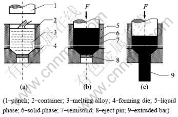
Fig 1 Illustration of liquid extrusion process: (a) Pouring melting alloy into container; (b) Closing mold and pressure keeping; (c) Extruding
Liquid, semi-solid and solid metal coexist in the container at the beginning of extrusion. When the extrusion starts, the workpiece in the container changes in two ways. On one hand, the workpiece is extruded out the exit of the mold. On the other hand, the liquid zone decreases with the workpiece solidifying. The deformation of the solidified zone and the flow of the liquid zone affect the forming process significantly. The top part of the workpiece crystallizes and moves down under high pressure with little deformation whereas the solid and semisolid workpiece near the exit deforms greatly. The central part of the extruded product will contain liquid metal without the deformed microstructure if the extrusion speed and the temperature are not controlled carefully. The extrusion process will not continue if much liquid metal is contained in the extruded product.
It can be drawn from the above mentioned characteristics of liquid solid forming process that the interface evolution and thermal mechanical analysis should be considered at the same time in the simulation. Unfortunately, the simulation is difficult to be implemented by conventional finite element method (CFEM) only. This is the purpose of this work.
3 Principle of extended finite element method (XFEM)
Stationary discontinuities, such as cracks and inclusions in materials, are difficult to be modeled with the conventional finite element method, which requires that the mesh conforms the geometric discontinuities. Modeling dynamic crack propagation or moving interface is even more cumbersome because the mesh must be updated continuously to match the geometry of the discontinuity as the crack progresses or interface evolves. Liquid-solid forming process includes typical moving interface because the temperature of the billet decreases continuously, as mentioned before in section 2.
The extended finite element method (XFEM) alleviates the shortcomings associated with CFEM in dealing the discontinuities presented in the problems. BELYTSCHKO and BLACK[15] used XFEM to solve the elastic crack growth problem with minimal remeshing. XFEM is based on the concept of partition of unity proposed by MELENK and BABUSKA[16]. LI and WANG[17] presented an overview and comments on the XFEM from basic theory to implementation procedure. ABDELAZIZ and HAMOUINE[18] also gave an overview and recent progress of the extended finite element method X-FEM in the analysis of crack growth modeling.
The interface between liquid and solid depends on the temperature of melting alloy. The standard finite element approximation of the temperature field is
 (1)
(1)
where Ni is the standard finite element shape function, and Ti represents the value of the temperature at node i. Shape functions Ni is constructed into the partition of unity, which means
 (2)
(2)
The following property is automatically satisfied for arbitrary function Y in the partition of unity
 (3)
(3)
The theoretical basis of the XFEM is the global solution of partition of unity finite element method (PUFEM), in which additional extended basis functions was used to reproduce the desired local feature, such as discontinuity. For PUFEM, Eq.(1) can be tailored into Eq.(4).
 (4)
(4)
where j j(x, t) is the discontinuous enrichment function (also means additional extended basis function ) defined for the set of nodes that the interface between liquid and solid is in its influence domain, as shown in Fig.2,  is the additional degrees of freedom.
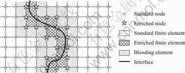
Fig.2 Schematic diagram of enrichments
According to Eq.(3), Eq.(4) can be rewritten as
 (5)
(5)
In the practical application, j j is replaced by  , which ensures Th(xi)=Ti.
In contrast to PUFEM, XFEM employs enrichment locally, which saves abundant computational resources, as it is equivalent to enriching only nodes close to discontinuity. In the extended finite element method, the conventional finite element mesh is produced. Then a few degrees of freedom are added to the selected nodes near the discontinuities to provide a higher level of accuracy.
4 Description of interface through level set method
XFEM was used to solve problems of evolving interfaces. In these applications, XFEM is often combined with the level set method for tracking interfaces. The level set method becomes a key ingredient of XFEM. In the level set method, the interface is represented implicitly by the zero of an isosurface of a function j j, a so-called level set function as shown in Fig.3. The interface evolution is then mapped into an evolution of the level set function with Hamilton�CJacobi equations, knowing the speed v of the interface in the direction normal to this interface. The relevant evolution equation is then given by requiring the material derivative of the level set function to vanish,
 (6)
(6)
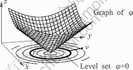
Fig.3 Level set function
Consider the domain W as illustrated in Fig.4, which is composed of solid region Ws and liquid region W1. The interface between solid and liquid is denoted by Gint and the subscripts s and l are used to denote solid and liquid phase, respectively.
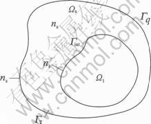
Fig.4 Evolution of interface
Let[12]
 (7)
(7)
be the distance of the point x from the transition interface at time t, we define the level set function j as the signed distance function from the interface:
 (8)
(8)
On the other hand, when the level set function is given, the interface Gint is the zero isocontour of j, namely,
 (9)
(9)
The level set approach can dramatically simplify the solution of many problems, such as interface evolution, dislocation evolution and crack growth. Besides, the interface evolution in the liquid metal infiltration process used to fabricate carbon fiber reinforced metal matrix composite also can be treated by the level set approach when the microstructure is not considered.
5 Implementation of XFEM in Abaqus code
Liquid-solid forming is a thermal mechanical coupled process. Mechanical equilibrium and thermal equilibrium must satisfy the static and stationary condition as Eq.(10):
 (10)
(10)
where K and KT are element stiffness matrix, u is displacement, T is temperature, F is force, and Q is thermal force.
 (11)
(11)
 (12)
(12)
where B=��N, D is the elastic modulus matrix, and k is the heat conductivity of materials.
K and KT are discontinuous because of the interface existing in the liquid-solid forming process. Discontinuous K and KT can be treated by XFEM through changing the properties of elements geometrically and physically. Geometric discontinuity is treated by modifying geometric matrix B with level set function. In this step the definition of enriched nodes is very important.
For the derivation of the finite element equations, it is convenient to write the enriched approximation Eq.(5) as

where
 (13)
(13)
 (14)
(14)
The shape function of elements containing enriched nodes is replaced by Eq.(13), which incorporates the level set function. This is also true for matrix B in the mechanical analysis from Eq.(11).
Properties of liquid are different from those of solid phase, which results in the discontinuity of D and k. Different D and k are chosen for liquid and solid. It is difficult to deal with D and k on the interface for the latent heat and complex mechanical behavior of semisolid. This will be a challenging research topic in the future.
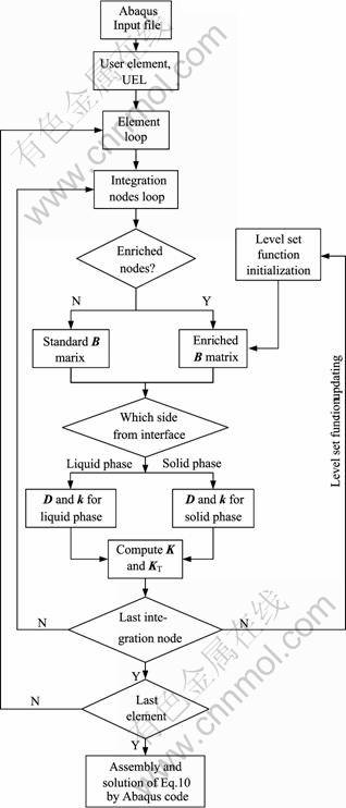
Fig.5 Flowchart of implementing XFEM on Abaqus code
Although the literatures widely reported the ease of implementation for such enrichment schemes, the practices showed that they are not easily incorporated into existing finite element codes.
Fig.5 shows the flowchart of XFEM implementation on general finite element analysis code Abaqus. User element (UEL) will be defined in the future. But due to short time for research, the procedure is still under compilation.
6 Conclusions
1) XFEM can be used to simulate the dynamic transition from liquid phase to solid phase in the process of liquid-solid forming based on the characteristics of the process and the ability of XFEM.
2) The flowchart of implementing XFEM on Abaqus code is illustrated based on UEL subroutine, which modifies the element stiffness matrix from the properties of materials and elements.
3) Sample simulation by UEL should be conducted to verify the feasibility of the proposed method in the future.
References
[1] LUO Shou-jing, LI He-jun. Research on the Deforming Load of Liquid Extrusion [J]. Chinese Journal of Mechanical Engineering, 1993, 6(2): 171-175.
[2] QI Le-hua, LI He-jun, CUI Pei-ling, SHI Zhong-ke. Forming of tubes and bars of Alumina/LY12 composites by liquid extrusion process [J]. Transactions of Nonferrous Metals Society of China, 2003, 13(4): 803-808.
[3] LI Run-xia, LI Rong-de, BAI Yan-hua, QU Ying-dong, YUAN Xiao-guang. Effect of specific pressure on microstructure and mechanical properties of squeeze casting ZA27 alloy [J]. Transactions of Nonferrous Metals Society of China, 2010, 20(1): 59-63.
[4] WANG Kai, LIU Chang-ming, ZHAI Yan-bo, ZOU Mao-hua. Microstructural characteristics of near-liquidus cast AZ91D alloy during semi-solid die casting [J]. Transactions of Nonferrous Metals Society of China, 2010, 20(2): 171-177.
[5] QI Le-hua, SU Li-zheng, JIANG Chun-xiao, ZHOU Ji-ming, LI He-jun. Research on the numerical simulation of liquid-infiltration-extrusion process for composites based on the rigid-viscoplastic FEM [J]. Materials Science and Engineering A, 2007, 454: 608-613.
[6] GERSTENBERGER A, WALL W A. An extended finite element method/lagrange multiplier based approach for fluid-structure interaction [J]. Computer Methods in Applied Mechanics And Engineering, 2008, 197(19/20): 1699-1714.
[7] KEN-ICHIRO M, KOZO O, MASANORI S. Finite element modelling of forming process of solid metal with liquid phase [J]. Journal of Materials Processing Technology, 1991, 27: 111-118.
[8] ZHOU Ji-ming, QI Le-hua, CHEN Guo-ding, ZHANG Yue-bing. Investigation on the couple deformation behavior of the solid metal with liquid phase under the pressure [J]. Journal of Plasticity Engineering, 2005, 12(Suppl): 129-134.
[9] QI Le-hua, ZHOU Ji-ming. Investigation on the numerical simulation for the dynamic transition from liquid to solid during liquid-solid extruding forming [J]. Solid State Phenomena. 2006, 116/117: 573-577.
[10] WANG Z G, INOUE T. Simulation of continuous casting process considering material flow [J]. Trans JSME A. 1987, 53: 1739-1742. (in Japanese)
[11] LI Chun-sheng, THOMAS B G. Thermo-mechanical finite element model of shell behavior in the continuous casting of steel [C]//ZHANG L C, LU G. Engineering Plasticity from Macroscale to Nanoscale Parts 1 and 2. Switzerland: Trans Tech Publications Ltd, 2003: 827-833
[12] SALVATORI L, TOSI N. Stefan Problem through Extended Finite Elements: Review and Further Investigations [J]. Algorithms, 2009, 2(3): 1177-1220.
[13] CHESSA J, SMOLINSKI P, BELYTSCHKO T. The extended finite element method (XFEM) for solidification problems [J]. International Journal for Numerical Methods in Engineering, 2002, 53: 1959-1977.
[14] MERLE R, DOLBOW J. Solving thermal and phase change problems with the extended finite element method [J]. Computational Mechanics, 2002, 28(5): 339-350.
[15] BELYTSCHKO T, BLACK T. Elastic crack growth in finite elements with minimal remeshing [J]. International Journal for Numerical Methods in Engineering, 1999, 45(5): 601-620.
[16] BABUSCARONKA I, MELENK J M. The partition of unity method [J]. International Journal for Numerical Methods in Engineering. 1997, 40(4): 727-758.
[17] LI Lu-xiang, WANG Tie-jun. The extended finite element method and its applications-A review [J]. Advances in Mechanics, 2005, 35(1): 5-20.
[18] ABDELAZIZ Y, HAMOUINE A. A survey of the extended finite element [J]. Computers & Structures, 2008, 86(11/12): 1141-1151.
(Edited by HE Xue-feng)
Foundation item: Project(50972121) supported by the National Nature Science Foundation of China; Project(20080004) supported by the Foundation of Key Laboratory for Advanced Materials Processing Technology, Ministry of Education, China
Corresponding author: ZHOU Ji-ming; Tel: +86-29-88488017, E-mail: zhoujm@nwpu.edu.cn

