
Effect of ion implantation upon erosion resistance of polyimide films in space environment
DUO Shu-wang(多树旺)1,2, LI Mei-shuan(李美栓)2, ZHOU Yan-chun(周延春)2
1. Jiangxi Key Laboratory of Surface Engineering, Jiangxi Science and Technology Normal University,Nanchang 330013, China;
2. Shenyang National Laboratory for Materials Science, Institute of Metal Research, Chinese Academy of Sciences, Shenyang 110016, China
Received 10 April 2006; accepted 25 April 2006
Abstract: The atomic oxygen (AO) resistance of Si ion implanted polyimide films in the ground-based AO simulation facility was investigated by scanning electron microscopy (SEM), X-ray photoelectron spectroscopy (XPS) and Auger electron spectroscopy (AES). The results show that at the initial stage of AO exposure the implanted sample has a small mass change, and then is stabilized. The erosion yield of the implanted polyimide film decreases by about two orders of magnitude compared with that of the polyimide film. The analysis through XPS and AES indicates that a continuous high-quality protective oxide-based (SiO2) surface layer is formed on the implanted polyimide films after the AO exposure. It can provide high-quality erosion protection for these materials. The implanted polyimide fully restores its original color and the carbonization effect disappears on the whole after AO exposure. Thermal-optical properties and surface morphology of the implanted polyimide materials are not altered. The modified materials have a markedly increased erosion resistance in AO environment.
Key words: atomic oxygen; ion implantation; surface modification; polyamide; erosion resistance
1 Introduction
Atomic oxygen (AO) materials on space vehicles in the low earth orbit (LEO) are exposed to atomic oxygen (AO). The O-atom number density at space shuttle altitudes is typically on the order of 109 cm-3. A body orbiting relative to this density in LEO, traveling at about 8 km/s, experiences a flux of 1015 O atoms/(cm2・s). The energy with which AO impinges on the spacecraft surface is approximately 5 eV [1, 2]. Because of their high strength to mass ratio, polymer materials and polymer-based composites are desirable for use in space applications. However, atomic oxygen causes surface erosion and performance degradation on such materials, although the erosion efficiency depends on the chemical structure of the polymer [3, 4]. For example, polyimide (named “Kapton” as a registered trade mark of DuPont) has been widely used as a flexible substrate for lightmass and high power solar arrays. When exposed in AO environment, the Kapton undergoes surface reaction evolution and mass loss. As a result, its thermal, optical and mechanical properties may degrade. The degradation of the Kapton may affect the mission performance significantly [4].
In order to prolong the service life and enhance the effectiveness of the spacecrafts, the development of new AO-resistant materials and protective coatings is needed. Numerous schemes are available to mitigate the AO damage to polymers and polymer matrix composites in LEO environment [5-7]. The coatings composed of inorganic materials such as Al2O3 and SiO2 can provide excellent AO protection [6], but they lack flexibility and easily crack. Through cracks, AO may undercut the substrate [8]. The difficulties of inorganic coatings associated with brittleness, mismatch of coefficients of thermal expansion, and morphology change due to atomic oxygen attack are overcame by creation of a highly protective oxide-based surface modified region. Thus, we focused on adoption of new surface modification method to protect materials against AO attack. The surface of implanted polymer based materials combines the advantages of inorganic materials and organic polymers. The technique eliminates the interface related weakness of inorganic coatings almost without changing the morphology of the substrate materials [9].
In this paper, we took an approach to improve the AO resistance of Kapton by silicon ion implantation in polyimde films. The AO exposure test of polyimide films was conducted in the ground-based simulation facility. The mass change of polyimide films was recorded during AO exposure. The surface morphology and chemical structure of the exposed polyimide films were investigated. The optical property of polyimide films before and after AO exposure were also tested.
2 Experimental
2.1 Materials
Polyimide H films with a dimension of 20 mm×20 mm×0.15 mm were cleaned in acetone and distilled water in an ultrasonic bath, and then dried before each AO exposure test and implantation. The Si ion implantation with nominal dosage of 7×10¹⁶ ions/cm2 was carried out by using the plasma immersion ion implanter. The samples were pulse-biased to 40 kV with a pulse width of 15 ?s and repetition rate of 100 Hz. The implantation current was about 1 A per pulse. The sample temperature was below 150 ℃.
2.2 AO erosion facility and test conditions
The ground-based tests of atomic oxygen erosion were carried out in a space environment simulator established at the Institute of Metal Research of Chinese Academy of Science. The working process of the facility was represented in detail in Ref.[10]. The AO beam with the density of 1016/(cm2・s) and energy of 5 eV could be obtained in the facility. During exposure, a vacuum level of about 10-3 Pa was maintained. For a test period of about 11 h, the AO flux was about 6×10²⁰ atoms/cm2.
2.3 Analysis methods
UV-Vis spectra were obtained in a Perkin-Elmer Lambda 900 UV-Vis-NIR spectrophotometer. The morphologies of the polyimide films before and after AO exposure test were observed with a Philips XL30 scanning electronic microscope (SEM) equipped with energy dispersive spectroscopy (EDS). The surfaces of the polymer samples were sputtering coated with a thin gold film before SEM observation in order to prevent charging. A VG ESCALAB MKⅡ XPS/AES was used to analyze the phases formed due to the surface reactions after exposure to AO flux.
3 Results and discussion
3.1 AO erosion kinetics
Fig.1 shows the AO erosion kinetics of Kapton and implanted polyimide films during the exposure for 11 h in AO ground simulation facility. As shown in Fig.1, the mass of the Kapton sample decreases continually, the mass loss is about 2 mg/cm2 under the test conditions. Kapton film undergoes degradation dramatically during exposed by AO flux. However, implanted polyimide films have a smaller initial mass loss that can be associated with a combined effect of mass loss due to volatile products formation and mass gain due to oxidation of implanted elements through oxygen uptake. The mass change then drops to zero, indicating formation of oxide based surface layer. This shows that the surface modification layer provides a very good resistance to AO erosion. The erosion yield of the implanted polyimide film derived from these experiments is about 5.0×10⁻²⁶ cm3/AO. The AO resistance of the modified polyimide increases by an order of 2-3 compared to that of the pristine polyimide depending on the ion dose and the energy of implanted ion. From the data on mass loss measurements of samples described above, confirmed as well by XPS and SEM (see below), it is clear that a stable, protective SiO2 surface structure is developed during AO exposure.
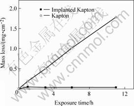
Fig.1 Mass change of ion-implanted Kapton and unimplanted Kapton under exposure to AO
3.2 Surface morphology analysis
All of the implanted polyimide films were subjected to a change of their initial colors, attaining light brown, dark brown or even black color shades with a graphite luster, similarly to many results for polymers implanted at higher energies and by other species [11, 12]. Graphite-like lustrous shade appears at strong carbonization of the surface layer after implantation. However, polyimide films implanted with Si, practically restored their color and degree of transparency after 2-4 h of AO exposure. In whole of AO test process, the surface were always smooth, and no subjected to AO erosion. Fig.2 shows the SEM images of Kapton. Before exposure, the surface structure was smooth and uniform. One of the major features of the interaction of AO with Kapton is the significant roughening of surface with the formation of carpet-like or cone-like structures (Fig.2(a)). Atomic oxygen apparently oxidizes and erodes Kapton. This is in agreement with the observations made for Kapton [1-3]. In contrast to these results, ion-implanted sample after AO exposure for 11 h, shows a smooth surface without any apparent erosion feature (Fig.2(b)). The ion-implanted modified layer appears to be quite stable in the AO environment and apparently protects the Kapton substrate from AO erosion.
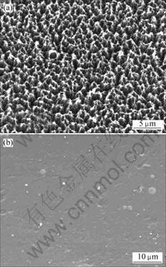
Fig.2 SEM images of Kapton: (a) Unimplanted; (b) Implanted with Si after AO exposure
3.3 Thermal cycling property
In order to evaluate the crack and spallation resistance of the modification layer, the samples were subjected to thermal cycling in the space simulator. The cyclic condition consisted of a range of temperature from -150 ℃ to 150 ℃ for a total of 30 cycles. The results indicate that no crack occurs, confirming that the coating is tightly adherent to the substrate. There is not apparent interface on the surface region of ion implanted polyimide film. The resistance of thermal cycling of implanted modified layers is very higher than that of inorganic coatings.
3.4 Surface structure and composition analysis
High-resolution XPS spectra of Si 2p obtained from the implanted polyimide films surface before and after AO exposure are shown in Fig.3. Variations in peak shapes and positions are observed between the AO exposed surfaces, indicating that the chemical species distribution is altered by exposure to the AO beam. The Si 2p peak that shifted 2.5 eV to a higher binding energy after AO exposure is centered at 103.6 eV, which corresponds to SiO2 [13]. These reveal the formation of a SiO2 layer with exposure to the 5 eV AO beam. When attacked by AO, this surface converts to ceramic-like SiO2 silicate. Increasing exposure to the AO flux results in formation of a silica layer on the surface, this layer acts as a protective barrier preventing further degradation of underlying polymer in the process of long exposure to the AO beam.
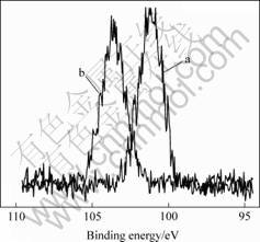
Fig.3 High resolution XPS spectra of Si 2p of ion-implanted Kapton sample before(a) and after(b) AO exposure
AES depth profile analysis reveals that the silicon is distributed in the sample up to above 100 nm in depth and the thickness of the formed oxide layer is about 30 nm (Fig.4). These results suggest that the concentration of implanted species is high enough to form a continuous high-quality protective oxide-based surface layer.
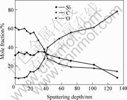
Fig. 4 Elements depth profile of ion-implanted Kapton sample after AO exposure
Based on above experimental results, the sequence of processes of the formation of implanted modification layer with protection polymer from AO erosion can be understood as follows. During the first stage, high doses of selected elements are implanted. During the implantation process, the surface region is enriched with the implanted ions, and various volatiles may be released from the surface simultaneously, leaving a carbonized surface layer. The second stage is a process of oxidative conversion of the surface of the implanted materials in an AO environment. At this stage some reactions take place at the same time. They include the oxidation of the remaining organic of the surface layer, the release of the formed volatiles, and the oxidation of the implanted elements, similar to surface conversion of organ silicones to SiOx based layers in oxygen plasmas [14]. The implanted layer is then gradually converted to a highly protective, uniform, oxide based, graded surface modified region which provide long-term protection for the original polymer beneath.
3.5 Optical property analysis
To evaluate the effects of ion-implantation upon the optical performance of polyimide, solar transmittance measurements were performed by using a laboratory spectro-reflectometer. In Fig.5, a comparison of the optical transmittance of the implanted polyimide film before and after the AO exposure with that of the pristine polyimide is presented. It can be seen the transmittance reduces substantially after implantation. The trans- mittance of the implanted polyimide film after the AO exposure is almost equal to that of the original polyimide film. The results indicate that the implanted polyimide fully restores their optical transparency and the carbonization effect almost disappears after AO exposure. The changes in optical transmittance are further indications of the conversion of at least the top surface of the implanted layer to a colorless transparent oxide-based material in 11 h of AO exposure. The modified surface
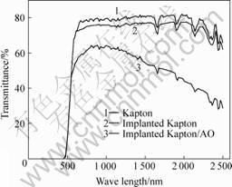
Fig. 5 Transmittance of Si ion implanted Kapton before and after AO exposure
layer that formed by ion implantation and oxidation conversion are very stable to the AO exposure.
4 Conclusions
The AO resistance of Si ion implanted polyimide films was tested in the ground-based AO simulation facility. At the initial stage of AO exposure, the implanted sample has a mass change, and then is stabilized. The erosion yield of the implanted polyimide film is 5.0×10⁻²⁶ cm3/atom and decreases by about two orders of magnitude compared with that of the polyimide film. The analysis through XPS and AES indicates that a continuous high-quality protective oxide-based (SiO2) surface layer forms on the implanted polyimide films after the AO exposure. It can provide high-quality erosion protection for these materials. The implanted polyimide fully restores their optical transparency and the carbonization effect disappears on the whole after AO exposure. The results by spectrophotometer show that the optical properties of coatings are not significantly altered. The modified materials increase erosion resistance markedly in AO environment.
References
[1] REDDY M R. Review: effect of low earth orbit atomic oxygen on spacecraft materials [J]. J Mat Sci, 1995, 38: 281-307.
[2] DEVER J A, BRUCKNER E J, SCHEIMAN D A, STIDHAM C R. Contamination and space environmental effects on solar cells and thermal control surfaces [J]. J Spacecr Rock, 1995, 32(5): 850-855.
[3] HOFLUND G B, EVERETT M L. Chemical alteration of poly(vinyl fluoride) Tedlar by hyperthermal atomic oxygen [J].App Surf Sci, 2005, 239(3-4): 367-375.
[4] REDDY M R, SRINIVASAMURTHY N, AGRAWAL B L. Atomic oxygen protective coatings for Kapton film [J]. Surf Coat Tech, 1993, 58: 1-17.
[5] TENNYSON R C. Protection of polymeric materials from atomic oxygen [J]. High Perform Polym, 1999, 11: 157-165.
[6] PACKIRISAMY S, SCHWAM D, LITT M H. Review: atomic oxygen resistant coatings for low earth orbit space structures [J]. J Mat Sci, 1995, 30: 308-320.
[7] KIEFER R L, ANDERSON R A, KIM M, THIBEAULT S A. Modified polymeric materials for durability in the atomic oxygen space environment [J].Nucl Instr Meth Phy Res, 2003, B208: 300-302.
[8] BANKS B A, SNYDER A, MILLER S K, GROH K K. Atomic-oxygen undercutting of protected polymers in low earth orbit [J]. J Spacecr Rock, 2005, 41(3): 335-339.
[9] UEDA M, TAN I H, DALLAQUA R S, ROSSI J O, BARROSO J J, TABACNIKS M H. Aluminum plasma immersion ion implantation in polymers [J]. Nucl Instr Meth Phy Res, 2003, 206: 760-766.
[10] DUO S W, LI M S, ZHANG Y M. A simulator for producing of high flux atomic oxygen beam by using ECR plasma sources [J]. J Mater Sci Tech, 2004, 20(6): 759-762.
[11] KLEIMAN J, ISKANDEROVA Z, TENNYSON R C. Ion implantation protects surfaces [J]. Advanced Materials & Processes, 1998, 4: 26-30.
[12] PIVIN J C. Hardening and embrittlement of polyimides by ion implantation [J]. Nucl Instr Meth Phys Res, 1994, B84: 484-490.
[13] BEAMSON G, BRIGGS D. High Resolution XPS of Organic Polymers: the Scienta ESCA300 Database [M]. New York: Wiley, 1992. 268.
[14] GILMAN J W, SCHLITZER D S, LICHTENHAN J D. Low earth orbit resistant siloxane copolymers[J]. J App Polym Sci, 1996, 60(4): 591-596.
(Edited by LI Xiang-qun)
Foundation item: Project (G19990650) supported by the National Key Basic Research and Development Program of China
Corresponding author: DUO Shu-wang; Tel: +86-791-3801423; Fax: +86-791-3801423; E-mail: swduo@imr.ac.cn

