Article ID: 1003-6326(2005)05-1040-05
Finite element analysis of free expansion of aluminum alloy tube under magnetic pressure
YU Hai-ping(于海平), LI Chun-feng(李春峰)
(School of Materials Science and Engineering, Harbin Institute of Technology, Harbin 150001, China)
Abstract: A link between the electromagnetic code, ANSYS/Emag and the structural code, Ls-dyna was developed, and the numerical modeling of electromagnetic forming for aluminum alloy tube expansion was performed by means of them (discharge energy 0.75kJ). A realistic distribution of magnetic pressure was calculated. The calculated values of displacement along the tube axis and versus time are in very good agreement with the measured ones. The maximum strain rate is 1122s-1, which is not large enough to change the constitutive equations of aluminum alloy. With the augment of discharge energy (0.5-1.0kJ), the relative errors of the maximum deformation increase from 2.93% to 11.4%. Therefore, coupled numerical modeling of the electromagnetic field and the structural field should be performed to investigate the electromagnetic forming with larger deformation.
Key words: electromagnetic forming; finite element analysis; magnetic pressure; strain rate CLC number: TG391
Document code: A
1 INTRODUCTION
Electromagnetic forming is one of the high rate forming methods, which uses intense magnetic field to form metal parts from plate and tube[1, 2]. The electromagnetic forming study consists of magnetic field and dynamic deformation analyses, which are coupled together[3]. So, the dependence of the system parameters on each other is the biggest obstacle to analyze electromagnetic forming.
In fact, it is the first wave of the magnetic pulse that provides energy for part forming. If the part forms little during the first wave, the system inductance and resistance will not change evidently. Therefore, the magnetic field and structural field have often been solved separately based on the assumptions that the coil and part are long enough to neglect the end effects[5-10].
Suzuki et al[10] assumed that magnetic pressure was the pulse load acting on the inner wall of tube, and the finite element analysis of electromagnetic forming for free tube expansion was performed by means of the RLC circuit method. The deformation equations were solved with Newmark integration method. In Ref.[11], the magnetic pressure involving end effects was obtained, which reflected the influence of vertical coordinate on the magnetic pressure distribution. However, the magnetic pressure stated above still neglected the axial component, and it was invalid when the coil was longer than the tube. Lee et al[3] introduced magnetic vector potential to Maxwell equations and obtained the magnetic pressure, which included the effects of coil and tube and was used as loads in Adina to analyze the dynamic deformation, whose accuracy was higher than that in Ref.[10].
Presently, researchers began to link the software that can calculate magnetic field and structural field separately to model the coupled field, such as modeling the armature startup behavior using EMAP3D/DYNA3D[12], the ball deformation of railgun using MEAG/DYNA3D[13] and electromagnetic forming for uniform tube-compression using ANSYS[14]. In this paper, a link is established between ANSYS/Emag and Ls-dyna to analyze the electromagnetic forming for free expansion of aluminum alloy tube by means of FEM. Realistic distributions of magnetic pressures in X, Y directions acting on the inner wall of tube are calculated. The high velocity deformation behavior and the strain rate are investigated, and the effects of discharge energy on calculating accuracy are compared.
2 FINITE ELEMENT ANALYSIS
This section consists of electromagnetic field and dynamic deformation analyses, which are performed in turn.
2.1 Electromagnetic field analysis
The dimension and the shape of the tube expansion system are illustrated in Fig.1. Only half view of the model is considered in this analysis because of its symmetry. A finite element mesh for the electromagnetic field and structural field is shown in Fig.2. 1335 axisymmetric quadrilateral elements with four nodes are used in electromagnetic analysis. Although the boundary of magnetic field is open space, the modeling region is limited by the computation capability and the efficiency. In this calculation, the dimension of the entire analysis region is four times half-length of the tube. In order to obtain the reliable results, finer meshes are used to describe the region of the coil and the tube. And the skin effects are considered in the meshes in the tube region.
The material properties of the tube expansion system are given in Table 1. The primary current is the same as that in Ref.[10] and is shown in Fig.3. The hypotheses used in the analysis are listed in Refs.[3, 14, 15]. lows. For the isotropic and linear magnetic medium, the density of magnetic field energy can be written as

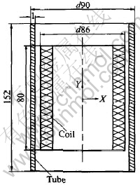
Fig.1 Electromagnetic forming system for tube expansion(Unit: mm)

Fig.2 Finite element mesh for tube expansion analysis
2.2 Structural field analysis
The calculating process of magnetic pressures action on the inner wall of the tube is given as fol-[CM)]
Table 1 Material properties of system[10]

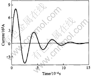
Fig.3 Primary current in analysis[10]
where ωm is the density of magnetic field energy, μ is the permeability, and B is the magnetic flux density.
The magnetic force solved by means of the virtual work principle[16] is expressed as

where Wm is the magnetic field energy, fm is the total magnetic force, and g is the generalized coordinate.
It can be known from Eqn.(2) that the decrease of magnetic field energy converts into magnetic field work. To the tube expansion by electromagnetic forming, the magnetic filed energy can be derived from Eqn.(1):

where V is the volume of gap between coil and tube, rti is the inner radius of tube, rco is the outer radius of coil, and l is the length of the gap.
According to Eqn.(2), the total magnetic force exerting on the inner wall of tube is

where the minus indicates the tendency of the magnetic force to reduce the gap. So, the magnetic pressure Pm can be expressed as
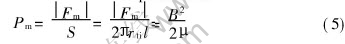
It can be known from the comparison of Eqns.(1) and (5) that the expression of magnetic pressure is the same as that of the density of magnetic field energy.
The finite element software ANSYS/Emag for electromagnetic field analysis is used to calculate the magnetic flux densities, Bx and By, along the inner wall of tube, which are substituted into Eqn.(5) to obtain the magnetic pressures in X, Y directions; and then the pressures are written and stored in the predefined array, which is a special data format provided in ANSYS. The elastic-plastic element code Ls-dyna is used to investigate the deformation process of the tube with the magnetic pressures, which are read from the ANSYS array aforementioned, as the loads are exerted on the inner wall of the tube. Only the first wave of magnetic pressures is considered, because the second wave is lower in amplitude than the first one and the increase distance between the coil and the tube further reduces the effects of the second wave[1].
The tube is the only component in the structural field analysis, which is described with 90 four-node quadrilateral elements, formulated through axisymmetric, area-weighted option. The explicit integration method is used to solve the motion equations on the discrete time in Ls-dyna, and the inertia effect is taken into account. The strain rate effect is neglected in the analysis, since aluminum alloy is insensitive to the strain rate at room temperature. And flow stress of the tube material[10] is approximated by
σ/MPa=162(ε+0.000663)0.411(6)
3 MODELING RESULTS AND DISCUSSION
As described in Fig.3, the time for the current up to the maximum is 80μs, and the cycle is 350μs. The distribution of axial magnetic flux density along the tube length corresponding to the maximum current is shown in Fig.4, and the maximum density is at the center of the tube wall, which is up to 2.56T. The change of radial magnetic pressure at the longitudinal center of tube versus time is shown in Fig.5, which is up to 2.65MPa at 80μs after the current starts to flow.
The comparison is illustrated in Fig.6 and Fig.7 between the modeling results in this work and the data in Ref.[10], which indicates that this modeling method is feasible under the discharge energy 0.75kJ. Fig.8 shows the change of the tube profile versus time, and deformation completes in about 250μs. And the peak radial veloci ty, 47.5m/s, at the center of the tube is observed at about 120μs, as shown in Fig.9. The equivalent plastic strain is shown in Fig.10. Although the oscillation in velocity still exists after the plastic deformation for the elastic oscillation of the tube, its value is so small that it cannot affect the calculating accuracy.

Fig.4 Flux density vs position along tube length
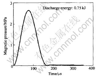
Fig.5 Magnetic pressure at longitudinal center of tube vs time

Fig.6 Comparison of radial displacement atlongitudinal center of tube

Fig.7 Comparison of final tube shape in experiment and modeling
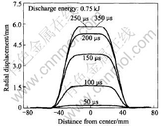
Fig.8 Tube profile vs time

Fig.9 Radial velocity at longitudinal center of tube
The change of the strain rate at the center of the tube versus time is shown in Fig.11, which is up to the maximum value 1122s-1 at about 127μs. In Ref.[17], the strain rate of the high velocity deformation in electromagnetic forming is not large enough to change the constitutive relations of tube material (102-103 vs 104s-1). Therefore, it is reasonable to neglect the strain rate effects in material model in this work.
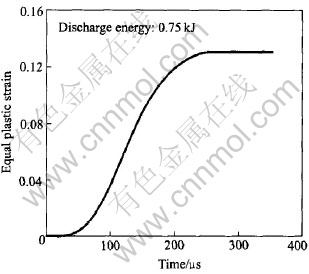
Fig.10 Equal plastic strain at longitudinal center of tube
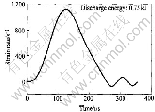
Fig.11 Strain rate at longitudinal center of tube
As shown in Fig.12, the modeling deformation results under three kinds of discharge energy are compared with the experimental data in Ref.[10]. The relative errors and the absolute errors of the maximum deformation with different discharge energy are indicated in Fig.13. It can be known from the above two figures that the errors between the modeling results in this work and the experimental data increase with the deformation, and the relative errors augment from 2.93% to 11.4%, which is caused by the neglect of effects of tube deformation on the magnetic field. Hence, the coupled field analysis of electromagnetic, structural fields should be performed to model electromagnetic forming with larger deformation.
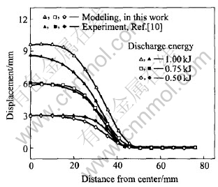
Fig.12 Comparison of final shapes with different discharge energies
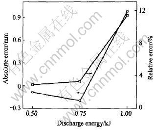
Fig.13 Errors of modeling results with different discharge energies
4 CONCLUSIONS
1) A link between the electromagnetic code, ANSYS/Emag and the structural code, Ls-dyna is developed, and the numerical modeling of electromagnetic forming for aluminum alloy tube expansion is performed by means of them, where the former calculates magnetic field and the latter does the high velocity deformation of tube. The modeling results of tube deformation agree well with the measured ones (discharge energy 0.75kJ).
2) With the augment of discharge energy, the tube deformation and the relative errors of the maximum deformation calculated by means of the separate method increase. Therefore, the coupled numerical modeling of electromagnetic and structural fields should be performed to investigate the electromagnetic forming with larger deformation.
3) The maximum strain rate is 1122s-1, which is not large enough to change the constitutive equations of aluminum alloy, so it is reasonable to discard strain rate effects of the forming materials in the modeling.
REFERENCES
[1]American Society for Metals. Metals Handbook (9thed), Vol.14, Forming and Forging [M]. Ohio: ASM International Handbook Committee, 1988. 644-653.
[2]LI Chun-feng. High Energy Rate Forming [M]. Beijing: China Machine Press, 2001. 1-65.
[3]Lee S H, Lee D N. A finite element analysis of electromagnetic forming for tube expansion [J]. Journal of Engineering Materials and Technology, 1994, 116(4): 250 - 254.
[4]Bendjima B, Srairi K, Feliachi M. A coupling model for analyzing dynamical behaviours of an electromagnetic forming system [J]. IEEE Transactions on Magnetics, 1997, 33(2): 1638-1641.
[5]Lai G K, Hillier M J. The electrodynamics of electromagnetic forming [J]. Int J Mech Sci, 1968, 10: 491-500.
[6]Suzuki H. Finite element analysis of tube deformation under impulsive internal pressure [A]. Proceedings of the 1st ICTP [C]. Tokyo, Japan, 1984. 367-372.
[7]Takatsu N. High-speed forming of metal sheets by electromagnetic force [J]. Int J Jpn Soc Mech Eng, 1988, 31(1): 142-144.
[8]Zhang H, Murata M, Suzuki H. Effects of various working conditions on tube bulging by electromagnetic forming [J]. Journal of Material Processing Technology, 1995, 48: 113-121.
[9]Hashimoto N. Electromagnetic forming of thin-walled metal tube with fine grooves [A]. Proceedings of the 4th ICTP [C]. Beijing, China, 1993. 533-538.
[10]Suzuki H, Negishi H, Yokouchi Y, et al. Free expansion of tube under magnetic pressure [J]. Journal of the Japanese Society for Technology of Plasticity, 1986, 27(310): 1254-1260.
[11]Beerwald C, Brosius A, Homberg W, et al. New aspects of electromagnetic forming [A]. Proceedings of the 6th ICTP [C]. Nuremberg, Germany, 1999. 2471-2476.
[12]David A, Hopkins, Francis S, et al. Analysis of startup behavior in a C-shaped armature using linked emap3d/dyna3d finite element codes [J]. IEEE Transactions on Magnetics, 1999, 35(1): 59-64.
[13]Hainsworth G, Lwonard P J, Rodger D. Finite element modeling of magnetic compression using coupled electromagnetic structural codes [J]. IEEE Transactions on Magnetics, 1996, 32(3): 1050-1053.
[14]YU Hai-ping, LI Chun-feng. Numerical modeling methods of electromagnetic forming and analysis of electromagnetic tube-compression [J]. Materials Science and Technology, 2004, 12(5): 346-34. (in Chinese)
[15]YU Hai-ping, LI Chun-feng, ZHAO Zhi-heng, et al. Magnetic pressure in electromagnetic aluminum tube-compression forming [J]. Trans Nonferrous Met Soc China, 2003, 13(special 1): 165-169.
[16]FENG Ci-zhang. Electromagnetic Field (2nd ed) [M]. Beijing: Higher Education Press, 2000. 163-174.(in Chinese)
[17]Vohnout V J. A Hybrid Quasi-Static/Dynamic Process for Forming Large Metal Parts from Aluminum [D]. Ohio State University, 1998.
Received date:2005 -01-16; Accepted date: 2005-04-26
Correspondence: YU Hai-ping, PhD candidate; Tel: +86-451-86413970; Fax: +86-451-86418753; E-mail: haipingy@hit.edu.cn
(Edited by YUAN Sai-qian)

