采用锌粉喷吹技术从熔融铅中除银
来源期刊:中国有色金属学报(英文版)2014年第2期
论文作者:V. H. GUTIéRREZ-PéREZ A. CRUZ-RAMíREZ M. VARGAS-RAMíREZ E. PALACIOS-BEAS R. G. SáNCHEZ-ALVARADO
文章页码:544 - 552
关键词:铅;银;粒径;粉末喷吹;沉降时间;除银率
Key words:lead; silver; particle size; powder injection; residence time; desilvering ratio
摘 要:采用锌粉喷吹技术从Pb-Ag合金中除银。所用锌粉粒径分别为3.55,44.4和734.8 μm,以氮气为输送气体,通过从顶部插入的一根喷管喷入熔体中。实验结果表明,采用粒径为44.4 μm的锌粉时,银的去除率最高,而采用较小粒径的锌粉时去除率最低。X射线衍射分析表明,采用粒径为44.4和734.8 μm的锌粉时,生成的渣中存在AgZn相,这与SEM-EDS分析结果相吻合。根据喷吹进入熔体中锌粉的熔化时间和沉降时间,对实验现象进行了解释。
Abstract: A silver removal process was carried out on a Pb-Ag alloy through zinc powder injection of three different sizes (3.55, 44.4 and 734.8 μm) with a top submerged lance using nitrogen as carrying gas. The higher silver removal was obtained for the zinc powder size of 44.4 μm, while the lowest silver removal efficiency was attained for the smaller particle size. The AgZn phase was detected in the slag for the 44.4 and 734.8 μm particle sizes by XRD, which was in agreement with SEM-EDS analysis. Experimental behavior was explained according to the melting and residence time of the injected particles.
Trans. Nonferrous Met. Soc. China 24(2014) 544-552
Silver removal from molten lead through zinc powder injection
V. H.  1, A.
1, A.  1, M.
1, M.  2, E. PALACIOS-BEAS1, R. G.
  1
1
1. ESIQIE, Instituto  Nacional, UPALM 07738,
  D.F., ;
2. CIIM-UAEH, Carretera Pachuca-Tulancingo Km 4.5, 42084, Pachuca, Hgo.
Received 18 June 2013; accepted 30 October 2013
Abstract: A silver removal process was carried out on a Pb-Ag alloy through zinc powder injection of three different sizes (3.55, 44.4 and 734.8 μm) with a top submerged lance using nitrogen as carrying gas. The higher silver removal was obtained for the zinc powder size of 44.4 μm, while the lowest silver removal efficiency was attained for the smaller particle size. The AgZn phase was detected in the slag for the 44.4 and 734.8 μm particle sizes by XRD, which was in agreement with SEM-EDS analysis. Experimental behavior was explained according to the melting and residence time of the injected particles.
Key words: lead; silver; particle size; powder injection; residence time; desilvering ratio
1 Introduction
Lead is one of the most widely used metals in the world, but it is highly toxic, posing risks for humans and for the environment if not been utilized or treated adequately [1]. Most of lead produced worldwide is used for manufacturing lead acid batteries, which constitute the largest market for lead. The growth in the number of vehicles and the associated demand of lead-acid batteries as well as the strict regulations of environmental authorities are creating the need to relocate, modernize and/or reconvert processes for both batteries and lead recycling to avoid a negative impact on the environment [2]. Secondary lead produced by recycling process has come to dominate much of the world market for lead. This has happened under immense social pressure to mitigate the environmental and health hazards of lead use and supply the material necessary to support economic growth in the industrial and emerging economies [3]. The recycled lead keeps the same physicochemical properties as primary lead and has become the raw material of this metal.
There are basically three methods for battery recycling: Separation of components through unity operations of mining treatment and pyrometallurgy or hydrometallurgy for the metal and paste treatment [4]. The pyrometallurgical process is composed of four stages: 1) grinding of the battery to separate plastic, electrolyte and lead plates; 2) lead reduction in rotary furnace; 3) separation of metallic lead from slag; and 4) refining of recycled lead [1]. The refining process consists in the removal of impurities and it is developed in the furnace or can be done as a separate operation in individual kettles. The refining stage involves three main processes: 1) the copper drossing or decoppering; 2) softening, and 3) desilvering. The copper drossing is a simple cooling process in a large kettle in which impurity compounds (mostly antimonies, arsenides, and stannides) are separated in either solid or immiscible liquid phases due to the decreasing solubility of the phases at lower temperatures. The impurities are removed by skimming during cooling, and the melt is finally cooled to about 340 °C. To remove the remains of the copper (to 20-200 g/t range), sulfur may be stirred into the melt, and cooling is continued to very near the melting point of the melt (~330 °C). The phases to be removed float on the lead surface and are called mattes or speiss, depending on their impurities. They are skimmed off, tapped off, or otherwise removed [3,5,6]. At this point, antimony, arsenic, tin, bismuth and any noble metals (primarily silver) are the major impurities remaining. The first three of these elements are removed in an oxidation process called softening. Silver is removed last, generally in primary lead refining. The removal of silver is performed in two stages [7]. First, zinc is added to lead bullion held at 500 °C, afterward the molten bath is cooled to around 350 °C at which a Ag-Zn-Pb crust forms on the top of the molten lead. The crust, which is subsequently removed from the process, is highly valued as it contains approximately 6% (mass fraction) silver. This material is then fire-refined to a final 99.999% (mass fraction) silver product. The difficulty for secondary plant is that whilst the process could be used for the removal of low levels of silver (i.e. up to 0.01%) in lead bullion, the same amount of zinc must be added as for high-silver primary bullion (up to 0.5%). The resultant crust would be very low in silver and, therefore, low in value. Thus, the process is very costly and does not give the benefit of silver credits [8]. At this point, the bullion is relatively pure lead.
In the smelting of primary lead, silver is considered to be a valuable by-product and is recovered during the refining process. In fact, most of the world’s silver is produced as a by-product of lead and copper smelting. The initial content of silver in the lead bullion can be up to 0.5%, and after subsequent refining the levels are below 0.001% in the final product. This is not the case in secondary smelting where the element is considered to be an impurity. Historically, silver levels in secondary lead have ranged from 0.001% to 0.005% (mass fraction) for most smelters world-wide, and these levels have been stable for many years [8]. However, with the development of new batteries, new alloys have been developed to decrease the positive grid corrosion at elevated temperatures and to increase voltage, and these requirements have led to the production of thinner grids made from corrosion resistant alloys as the Ca-Sn-Ag alloys [8-13] for use in automotive batteries. The level of silver is rapidly increasing in recycled lead streams throughout the world approaching to the upper limits of many specifications. The problem now facing the secondary smelters is that whilst there is a method for removing silver, it is a very costly exercise due to the low level of silver present in relation to primary smelting. The procedure of adding zinc powder onto the lead surface and further stirring to remove silver is an inefficient step in lead refining. A technique for increasing the efficiency of lead refining is the submerged injection of solid reagents into melts. PLASCENCIA et al [14] developed experiments to remove copper from lead bath by conventional top addition and injection of sulfur powder. The injection efficiency depends mainly on the interaction (solid particles and conveying gas) with the liquid metal. Typical factors to consider are the real contacting interfacial area and the residence time between the liquid metal and solid particles [15]. Powder injection process considers two possible reaction zones [16]. These are the transitory reaction zone (reaction between the particles injected and liquid metal) and the permanent reaction zone (reaction between the metal-slag interfaces). The residence time of the particles is determined by their velocity relative to the melt and by the bulk flow velocity of the melt. If the particles have low settling velocities, their motion will be controlled by the bulk circulation generated by the bubble plume. If they remain in the vicinity of the lance tip upon injection, they will be rapidly carried by the plume to the upper surface of the melt with low utilization efficiency [17].
This works deals with the silver removal from a Pb-Ag alloy through the zinc powder injection with nitrogen as conveying gas. The effect of the zinc powder size (3.55, 44.4 and 734.8 μm) is evaluated to determine the highest zinc efficiency in silver removal. The slag is analyzed by X-ray powder diffraction and scanning electron microscopy with energy dispersive spectra techniques. The residence and melting time are determined in order to explain the experimental behavior.
2 Experimental
2.1 Pb-Ag alloy production
According to the literature review, silver contents are reaching levels higher than 0.01% in the secondary lead refining [8]. Thus, in this work a master alloy Pb-Ag with 0.0132% Ag was manufactured by conventional melting in an electric furnace at 650 °C from pure metals. 11 kg of alloy was melted in a SiC crucible and poured into an iron mold to obtain ingots of approximately 900 g each one.
2.2 Zinc powder production
Three sizes of zinc powder were used as raw materials for the injection trials. J. T. Baker commercial reagents of zinc were used in granular and powder presentation with 99.9% and 99.8% of purity, respectively. The third size was obtained by mechanical milling of granular zinc in a mill Spex 8000. The container used was made of hardened steel with zirconium balls and 10% methanol was added as process control agent to avoid excessive agglomeration. The milling was carried out for 30 min under argon atmosphere. The samples were classified with an optical microscope Carl Zeiss Axiovert 40-MAT and SEM Jeol 6300. The three sizes of zinc powder were named as fine, middle and coarse particles.
2.3 Injection trials
Figure 1 shows schematically the experimental arrangement used to develop the injection trials. It consists of a SiC crucible of 2 kg capacity to melt the Pb-Ag master alloy. The heating system was an electrical furnace enabled with the control of temperature to within ±3 °C of the set values. The temperature was measured with a K-type thermocouple. The injection system consisted of a sealed chamber where zinc powder was charged and it was joined to an stainless steel lance with an inner diameter of 3.6 mm. Nitrogen of commercial purity was used as conveying gas. Five melting-injection trials were carried out for each of the three sizes of zinc. According to the mass charge (Pb-Ag alloy), the stoichiometric amount of zinc was added considering the following reaction.
Ag+3Zn=AgZn3 (1)
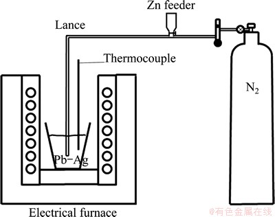
Fig. 1 Schematic diagram of injection trials
The following experimental parameters were kept constant: temperature of 485 °C, distance between the lance and crucible bottom of 10 mm, nitrogen gas flow rate of 1.6 L/min and injection time of 7 s. Samples of molten lead were taken out before and just after each injection with a silica tube by suction and the slag was removed before pouring the melt into metallic molds. The silver content in the metallic samples was determined using a Perkin Elmer 300 atomic spectrometer [18]. The slag was characterized by XRD and MEB/SEM techniques.
2.4 Slag characterization
The size, morphology and qualitative chemical analysis of slag obtained were determined with the SEM Jeol 6300 and with the energy dispersive spectra (EDS) analysis. An Au-Pd film was deposited on the surface of the slag to make them conductive. Images were obtained with backscattering electrons at 15 kV and 10 A. In addition, the slag was analyzed in an X-ray diffractometer Bruker D8 Focus with monochromatic Cu Kα radiation working in θ/2θ configuration. Data were collected in an angular range from 20° to 80° with a step size of 0.02° and a counting time of 2 (°)/min.
3 Results and discussion
3.1 Morphology and particle size distribution
Figures 2, 3 and 4 show the morphology and particle size distribution of the three zinc powders used for injection trials. Figure 2 shows the spherical zinc particles with a narrow size distribution in the range from 1 to 9 μm, typical of gas atomized metals. Figure 3 shows a broad size distribution of flattened zinc morphologies in the range from 1 to 95 μm; it is evident that large flattened particles are deformed plastically due to the milling process. Large flattened zinc particles with a broad size distribution in the range from 242 to 2000 μm are observed in Fig. 4.
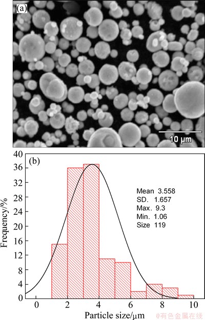
Fig. 2 Morphology of fine zinc powder (a) and its particle size distribution (b)
3.2 Injection trials
Table 1 shows the results of the injection trials for the three sizes of zinc particle. The amount of Pb-Ag alloy with its corresponding stoichiometric zinc amount, the initial (w(Ag)initial) and final (w(Ag)final) content of silver in the alloy and the ratio (w(Ag)final/w(Ag)initial) are presented in Table 1. The amount of zinc added considers reaction (1) and the silver content of 0.0132% in the Pb-Ag alloy. The silver removal (η) is presented as desilvering fraction, which is calculated according to the following expression: η=1-w(Ag)final/w(Ag)initial. An average desilvering efficiency of 6%, 18% and 13% was obtained for the fine, middle and coarse zinc particles, respectively. Figure 5 shows the desilvering fraction for the three zinc particles. The best desilvering fraction was obtained for middle particle size and the worst result was attained for the fine particle size. As can be observed in Fig. 5, there is a high dispersion on the experimental results, which is directly related with the particle size distribution for the three sizes. The middle size presents the best desilvering value; however, this silver removal efficiency could be increased up to a value of 28% or decreased to a value of 7%. For this particle size, it must be required to decrease the wide particle size distribution in order to increase the silver removal. The fine particle size achieves the lower silver removal, contrary to the expected due to its higher surface area which increases the reaction kinetic. In order to explain the experimental results, the residence and melting time are obtained. The residence time represents the time spent for the particles to reach the liquid surface after they leave the lance tip supported with the conveying gas. The residence time is calculated based on the efficiency of the transitory reaction given by OHGUCHI and ROBERTSON [19] with Eq. (2).
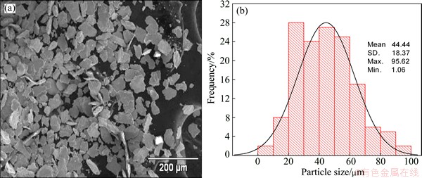
Fig. 3 Morphology of middle zinc powder (a) and its particle size distribution (b)
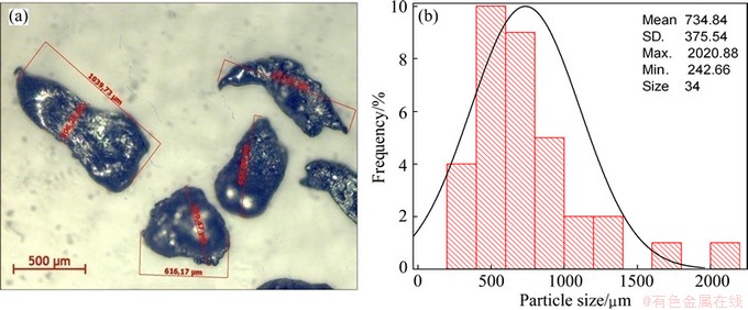
Fig. 4 Morphology of coarse zinc powder (a) and its particle size distribution (b)
Table 1 Experimental results of injection trials
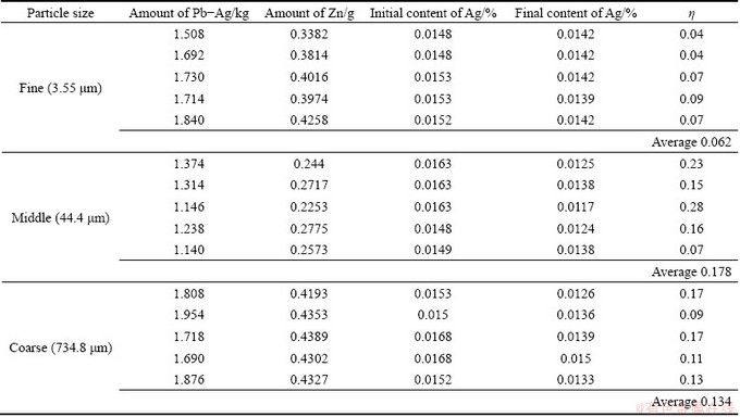
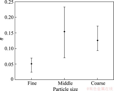
Fig. 5 Effect of particle size on desilvering efficiency
 (2)
(2)
where E is the efficiency of the transitory reaction, Ap is the particle area, ke is the mass transfer coefficient, τe is the residence time, Leq is the equilibrium coefficient of silver concentration in the particle and Vp is the particle volume. Rearranging terms and solving for the residence time, Eq. (2) is represented as follows:
 (3)
(3)
The value of the efficiency of the transitory reaction is in the range from 0 to 1. When E=1, the silver particle reacts totally with the molten lead in the residence time. The equilibrium coefficient of silver concentration in the particle (Leq) is obtained by
 (4)
(4)
where w(Ag) is the silver particle content when it reaches the liquid surface; w(Ag)eq is the silver content in thermodynamic equilibrium at the process temperature in the bath metal; both are in mass fraction. The following parameters were obtained in a previous work developed by  et al [20,21]: E=0.25, Leq=230.4147 at 480 °C. The mass transfer coefficient is determined by [22]
 (5)
(5)
where r is the radius of the particle (m), D is the zinc diffusion coefficient (2.3493×10⁻⁹ m2/s), ε is the specific mixing power (W/kg) and υ is the zinc kinematic viscosity (1.646×10⁻⁷ m2/s). The specific mixing power is represented by [16]
 (6)
(6)
where M is the mass of molten metal, Q is the volumetric flow of conveying gas (m3/s), T is the bath temperature (K) and H is the bath depth (0.057 m). Substitution of Eqs. (4), (5) and (6) into Eq. (3) gives the residence time. The residence time calculated with the Ohguchi’s model was 0.01, 0.51 and 11.3 s for the fine, middle and coarse particle size, respectively.
The rate of solidification or melting is a measure of the advance in the solid-liquid interface and it is determined by the relative magnitude of the resistance to heat transfer from the metal to the surrounding or vice versa. Considering an energy balance, the rate at which heat is transferred from the environment to the solid metal equals the rate of absorption of latent heat of fusion. Assuming that the temperature gradient in the environment is very small, therefore, the environment can be considered to be semi-infinite [23]. The time required to full melting of a cylinder or a sphere in a semi-infinite medium can be calculated by
 (7)
(7)
where Lc is the characteristic length; Vs represents the volume of solid metal; A is the solid metal surface area; T0 is the initial temperature of the solid metal; Tf represents the metal melting temperature; ρs is the density of solid metal; △Hfs is the latent fusion heat of metal; km represents the thermal conductivity of the medium; cp,m is the specific heat capacity of the medium: ρm is the density of the medium; tf represents the melting time; R is the radius of the cylinder or sphere; and n is the form factor in heat conduction and it is 1 and 2 for a cylinder and sphere, respectively. The characteristic length must include the whole zinc mass injected in the desilvering reaction in order to consider different particle sizes in the melting time determination [23]. Therefore, a characteristic length was considered constant for the three particle sizes in this work. For all the injection trials, an average zinc mass of 0.36 g was considered which is represented as a zinc spherical particle with a volume of 5.0422×10⁻⁸ m3 and an area of 6.6×10⁻⁵ m2. Therefore, Lc was determined to be 76.39×10⁻⁵ m. The zinc mass was considered the solid metal while the molten lead was the medium. By substitution of Lc and the data reported in Table 2 into Eq. (7), an equation was obtained that can be solved numerically to obtain the melting time. The melting time calculated was determined to be 0.041 s for the three particle sizes evaluated. Figure 6 shows the results obtained in the residence and melting time determination related with the particle size. The fine zinc particle shows a residence time of 0.01 s which is lower than the melting time (0.041 s) required to the full melting of zinc particles. This means that, the particle reaches immediately the liquid surface without fully melting to be retained in the slag phase. The middle size zinc particle shows a residence time of 0.51 s, more than 12 times the time required to fully melt zinc particle. In this case, particles remain in molten lead after coming out the lance tip and then fully melt and finally they reach the liquid surface. The coarse size zinc presents the highest residence time of 11 s, almost twice the injection time. After completing the injection, the coarse zinc particles still remain in molten lead. Therefore, coarse particles have enough time to coalesce between them to form big drops of zinc before they reach the liquid surface.
Table 2 Parameters considered in calculation of melting time
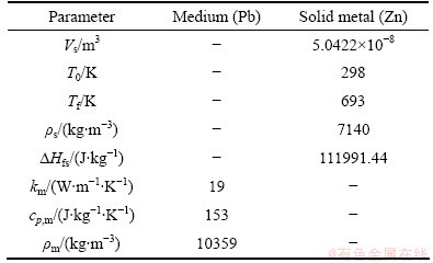
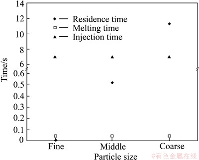
Fig. 6 Effect of particle size on melting and residence time
3.3 Slag characterization
The slag obtained by the injection trials was characterized by X-ray powder diffraction and the results are shown in Fig. 7. The major component for the three sizes evaluated was lead (JCPD file 4-0686) in the alloy. The low amount of lead oxide was identified as PbO-ortho (JCPD file 5-0570) and PbO-tetra (JCPD file 5-0561) for the fine size zinc particle and only PbO-ortho was determined for the middle and coarse sizes zinc particle. A zinc oxide phase (JCPD file 13-0311) was detected for the fine and middle size. In spite of using an electrical furnace and a silicon carbide crucible to minimize oxidizing conditions, the presence of oxide phases was unavoidable. The slag with fine size showed a high amount of ZnO2 phase, which indicates that zinc particles reach the liquid surface without reaction and later are oxidized. The slag with middle size zinc particle presented a lower zinc oxide amount and the presence of AgZn compound (JCPD file 29-1156) which was also detected in the case of coarse size but in a lower quantity. This AgZn compound represented the ideal composition of the β phase, stable at high temperature in the Ag-Zn binary system [24]. In this work, the AgZn3 compound was considered to be formed according to Reaction (1); however, after injection trials, the equilibrium was attained for the AgZn compound. In spite of the low amounts of silver and zinc used in the developing of the injection trials, it was possible to identify the AgZn compound for the middle and coarse sizes, which indicates the silver removal from the molten lead. The SEM-microanalysis results of the slag obtained by injection trials are shown in Fig. 8. The morphology of the slag and X-ray mappings of Zn and Ag are presented in Fig. 8. The X-ray mapping image shows a contrast due to element concentration gradient. As can be observed, in the case of fine size, there is a high zinc concentration without presence of silver. In addition, the slag morphology presents spherical particles, similar to those obtained in the zinc particle size distribution of Fig. 2. Therefore, the zinc injected reaches the liquid surface without reaction to form a stable slag layer, which is in agreement with X-ray powder diffraction and chemical analysis in the desilvering process. The slag with middle and coarse size zinc particles shows a high concentration of silver and zinc, homogeneously distributed in the slag, which supports the X-ray powder diffraction results in the AgZn compound formation and in the silver removal from molten lead. It was possible to observe that coarse size zinc particles present an agglomeration. The residence time for coarse particles (11 s) into molten lead is the longest for the three particle sizes. During this time, three possible cases may happen: the first and more unlikely is that zinc forms a solid solution with lead and this case is minimized due to the limited solubility of Zn in Pb according to its binary diagram system [24]; the second and more probably is that zinc reacts favorably with silver to form AgZn compound in the slag phase according to the Ag-Zn binary diagram system [24]; and the third is that big particles coalesce into an agglomeration of particles in the slag phase, which partially reacts with silver as observed in MEB results. It must be stressed out that the hydrodynamic and kinetic behavior of the lance-crucible system must be considered in order to have a better comprehension of particle behavior into molten lead with the carrier gas [25].
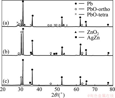
Fig. 7 XRD patterns of slag obtained using fine (a), middle (b) and coarse (c) zinc particle
The conventional process [20,21] was reported that an amount of 2% Zn of the lead charge is required to obtain a desilvering fraction of 0.07 with a Zn efficiency of 1.8%. In our cases, for the middle size zinc powder, an average amount of 0.02% Zn of the lead charge was added to obtain a desilvering fraction of 0.18 with a Zn efficiency of 18% in average. Therefore, the injection process reduces zinc consumption and a shorter time is required to remove silver from lead.
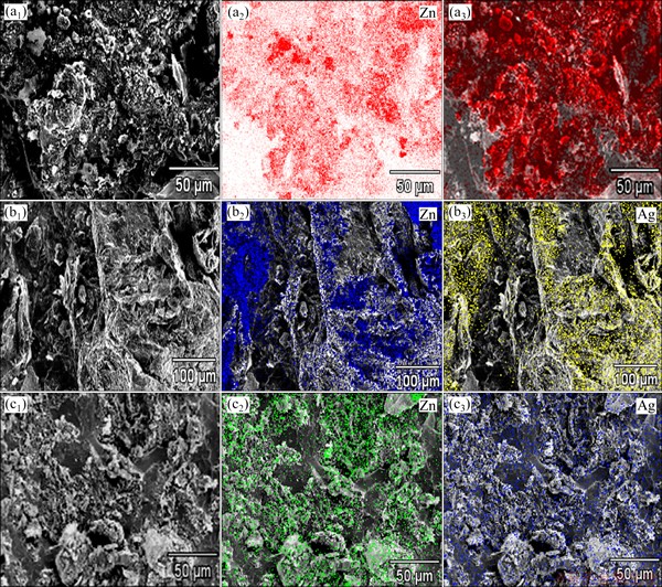
Fig. 8 X-ray mappings of Zn and Ag elements obtained for slag with injection of fine (a1, a2, a3), middle (b1, b2, b3) and coarse (c1, c2, c3) zinc particles
4 Conclusions
The effect of injection of three size zinc particles on the silver removal from a Pb-Ag alloy was studied. The zinc particles in sizes of 44.4 and 734.8 μm achieve the higher desilvering ratio of 0.178 and 0.134, respectively, whereas the zinc particles in size of 3.55 μm present a low desilvering ratio of 0.062. The residence time of the particle was determined to be 0.01, 0.51 and 11.0 s for the particle in size of 3.55, 44.4 and 734.8 μm, respectively, while the melting time was determined to be 0.041 s. The compound AgZn was found in the slag for the zinc particle in size of 44.4 and 734.8 μm by X-ray powder diffraction. The SEM-microanalysis results of the slag are in agreement with those obtained by X-ray powder diffraction. A relationship between the residence, melting and injection times was established to explain the experimental results in desilvering efficiency. The injection process represents an attractive route for secondary lead producers in the silver removal from molten lead.
Acknowledgements
The authors wish to thank the Institutions CONACyT, SNI, COFAA and SIP-Instituto Nacional for their permanent assistance to the Process Metallurgy Group at ESIQIE-Metallurgy and Materials Department.
References
[1] KREUSCH M, PONTE M, PONTE H, KAMINARI N, MARINO C, MYMRIN V. Technological improvements in automotive battery recycling [J]. Resources Conservation and Recycling, 2007, 52: 368-380.
[2] VALDEZ H. Lead battery markets and recycling in Mexico and South America [J]. J Power Sources, 1997, 67: 219-223.
[3] ELLIS T, MIRZA A. The refining of secondary lead for use in advanced lead-acid batteries [J]. J Power Sources, 2010, 195: 4525-4529.
[4] JOLLY R, RHIN C. The recycling of lead-acid batteries: Production of lead and polypropylene [J]. Resource, Conservation and Recycling, 1994, 10: 37-43.
[5] RAMACHANDRA S. Resource recovery and recycling from metallurgical wastes: Waste management series 7 [M]. 1st edition. The Netherlands: Elsevier B V, 2006.
[6] DAVEY T. The physical chemistry of lead refining, lead-zinc-tin [M]. 1st edition. USA: TMS, 1980.
[7] WOODCOCK J T, HAMILTON J K. Australasian mining and metallurgy: The Sir Mawby memorial [M]. 2nd Ed. Parkville Vic: Australasian Institute of Mining and Metallurgy, 1993.
[8] STEVENSON M, MANDERS J, ECKFELD S, PRENGAMAN R. Impact of modern battery design and the implications for primary and secondary lead production [J]. J Power Sources, 2002, 107: 146-154.
[9] PRENGAMAN R. Improvements to active material for VRLA batteries [J]. J Power Sources, 2005, 144: 426-437.
[10] BAUER J, STANDKER-THIEMANN C. Electro grid for lead storage batteries [P]. US 6210837. 2001.
[11] DAVIS J. Corrosion resistant lead alloy for lead-acid batteries [P]. US 6114067. 2000.
[12] RAO P, UHLEMANN T F. Sealed lead-acid cells and batteries [P]. US 5691087. 2000.
[13] RAO P, UHLEMANN T F, LARSON J, STEVEN R. Battery grids and plate and lead-acid batteries made using such grids and plates [P]. US 5434025. 1995.
[14] PLASCENCIA G, ROMERO A, MORALES R, HALLEN M, CHAVEZ F. Sulfur injection to remove copper from recycled lead [J]. Canadian Metallurgical Quarterly, 2001, 40(3): 309-316.
[15] EMI T, YIN H. Injection metallurgy in steel industry current and future development [C]//The Howard Worner International Symposium on Injection in Pyrometallurgy. USA: TMS, 1996: 19-38.
[16] VARGAS M, ROMERO A, MORALES R, HERNANDEZ M, CHAVEZ F, CASTRO J. Hot metal pretreatment by powder injection of lime-based reagents [J]. Steel Research, 2001, 72(5): 173-181.
[17] LANGBERG D, NILMANI M. The injection of solids using a reactive carrier gas [J]. Metallurgical and Materials Transactions B, 1994, 25: 653-660.
[18] Analytical methods for atomic absorption spectrometry [M]. Perkin-Elmer, 1994: 73-93.
[19] OHGUCHI S, ROBERTSON D. Kinetic model for refining by submerged powder injection: Part 1 transitory and permanent-contact reactions [J]. Ironmaking and Steelmaking, 1984, 11(5): 262-273.
[20] RODRIGUEZ J. Study of silver removal from liquid lead by zinc powder injection [D]. ESIQIE-IPN, D F, 2003.
[21] ROMERO A, MORALES R, CHAVEZ F, LOPEZ S, Y PALAFOX J. Removal of copper, nickel and silver from liquid lead [R]. IPN-ENERTEC Project. Metallurgy Department, ESIQIE-IPN, D F, 1999.
[22] NILMANI M, LANGBERG D. The production of nickel-zinc alloys by powder injection. metallurgical processes for early twenty-first century [M]. 1st Edition. USA: TMS, 1994.
[23] GASKELL D. An introduction to transport phenomena in materials engineering [M]. 1st edition. New York: Macmillan Publishing Inc, 1992.
[24] MASSALSKI T B. Binary alloy phase diagrams [M]. 2nd edition. USA: ASM, 1990.
[25] GUTIERREZ V, VARGAS M, CRUZ A, ROMERO A. Hydrodynamic analysis of particle injection during lead refining [J]. Acta Universitaria, 2011, 21(1): 29-35.
采用锌粉喷吹技术从熔融铅中除银
V. H. 1, A. 1, M. 2, E. PALACIOS-BEAS1, R. G. 1
1. ESIQIE, Instituto Nacional, UPALM 07738, D.F., ;
2. CIIM-UAEH, Carretera Pachuca-Tulancingo Km 4.5, 42084, Pachuca, Hgo.
摘 要:采用锌粉喷吹技术从Pb-Ag合金中除银。所用锌粉粒径分别为3.55,44.4和734.8 μm,以氮气为输送气体,通过从顶部插入的一根喷管喷入熔体中。实验结果表明,采用粒径为44.4 μm的锌粉时,银的去除率最高,而采用较小粒径的锌粉时去除率最低。X射线衍射分析表明,采用粒径为44.4和734.8 μm的锌粉时,生成的渣中存在AgZn相,这与SEM-EDS分析结果相吻合。根据喷吹进入熔体中锌粉的熔化时间和沉降时间,对实验现象进行了解释。
关键词:铅;银;粒径;粉末喷吹;沉降时间;除银率
(Edited by Sai-qian YUAN)
Corresponding author: A. ; Tel: +52-55-5729-6000-54202; Fax: +52-55-5273-2996; E-mail: alcruzr@ipn.mx
DOI: 10.1016/S1003-6326(14)63094-6

