
Numerical simulation of warm compacted synchronous pulley
ZHOU Zhao-yao(周照耀), ZHAO Wei-bin(赵伟斌), LI Yuan-yuan(李元元)
CHEN Pu-qing(陈普庆), NGAI Tungwai Leo(倪东惠), CHEN Wei-ping(陈维平)
College of Mechanical Engineering, South China University of Technology, Guangzhou 510640, China
Received 8 June 2005; accepted 17 October 2005
Abstract: A new mechanical model for warm powder compaction was presented. Warm compaction process of iron-based powder was investigated to deal with the existence of elastic, plastic and thermal strains. A coupled mechanical and thermal model was developed based on ellipsoidal yield criterion and continuum theory. The constitutive equations were integrated into the constitutive integral arithmetic and solved employing incremental iterative solution strategy. The flow stress model of iron powder was nonlinearly fitted according to uniaxial warm compaction. The constitutive model was implemented into user-subroutines of MSC.Marc. With the equations, algorithms and programs developed, the compaction procedures of a complex synchronous pulley were simulated. Two different compaction schemes with different punch displacements were tested and the relative density distribution was obtained. Comparison with experimental data shows that the homogeneity of green compact is greatly affected by the compaction mode. The simulation results agree with the experiments very well.
Key words: metal powder; finite element method; warm compaction; relative density
1 Introduction
In powder metallurgy manufacturing process, quality of green compacts obtained from the compaction procedure is essential to the performance and precision of the final products. The mechanical behavior of powder in warm compaction involves complicated nonlinear phenomena, i.e., special nonlinear mechanical characteristics of powder material, large displacement and large strain, continuously changing contact condition between the metal powder and die, changing frictional force with changing relative density, as well as the thermal effect due to plastic deformation or friction[1-7].
In the past three decades, different kinds of Elliptical Cap yield models based on von Mises yield criterion have been deduced and investigated by researchers such as Green[8], KUHN and DOWNEY [9], SHIMA and OYANE[10] and Doraivelu[11]. FLECK et al[12] proposed a micromechanical particle model based on Fleck model which was appropriate in the high porosity stage. Gurson[13] model was usually used in the low porosity stage. In the transition stage, Redanz et al[14, 15] developed a linear combination of Fleck and Gurson model. Bocchini[16] analyzed the decrease of powder’s yield stress in warm compaction quantitatively. Ariffin et al[17] developed a yield criterion considering the temperature and hardening effect, but there was no expatiation on the hardening model and simulation parameters.
The aim of this paper is to achieve a good numerical simulation of warm compaction. The thermal-elasto-plastic constitutive equations suitable for powder material obeying ellipsoidal yield criterion were developed. The constitutive equations were integrated into the constitutive integral arithmetic. A large displacement finite element method considering updated Lagrangian strategy was adopted to solve the coupled mechanical and thermal nonlinear problem.
2 Coupled thermal and mechanical model
The warm powder compaction is modeled using a thermo-elastoplastic constitutive law.
2.1 Yield criterion
For isotropic materials, the yield criterion may be formulated as[9]
 (1)
(1)
where  and J1 are the second invariant of deviator stress component and the first invariant of stress tensor, respectively. A and B are state variants pertinent to the plastic strain
  . In kuhn’s model:
 ,
,  ,
,  .
.
where  is the yield stress of the porous metal. Y0 is the yield stress of non-porous metal.
  is a function of relative density(ρ), which should be determined by experiments.
Differentiating Eqn.(1) yields
 (2)
(2)
where
 (3)
(3)
 (4)
(4)
Relationship between elastic stress and strain are
 (5)
(5)
The corresponding stress increment of warm compaction is
 (6)
(6)
According to Eqn.(3), the elastic stress and strain relation taking temperature into account is
 (7)
(7)
Compared with the expression neglecting the temperature effect, Eqn.(6) has one more term,  .
.
Eqn.(2) can be expressed as
 (8)
(8)
Substituting Eqn.(3) and rearranging yields
 (9)
(9)
Then Eqn.(8) can be written as

 (10)
(10)
The elasto-plastic matrix  is defined as

where  (defined as plastic matrix ) has the form as
 (11)
(11)
2.2 Calculation of thermal strain increment
The thermal strain increment  is defined as
 (12)
(12)
where  is the thermal expansion coefficient of porous metal, the relation between and
  can be expressed as[18]
 (13)
(13)
 (14)
(14)
where E, α0 and  are the elastic modulus, thermal expansion coefficient and Poisson’s ratio of non-porous metal, respectively; Eρ is the elastic modulus of porous metal.
2.3 Strain hardening
Strain hardening expression of non-porous metal is[18]
 (15)
(15)
 (16)
(16)
where K and n are the strength coefficient and strain hardening exponent of non-porous metal respectively;  and
and  are the apparent plastic strain and strain rate of non-porous metal respectively, Q and Rg are deformation activation energy and gas constant, respectively; A, β, m, εs are constants.
2.4 Material hardening
During compaction, the yield surface changes when the powder gets denser. The relationship of the relative density and flow stress was obtained based on the uniaxial warm compaction. The experimental results are nonlinearly fitted as shown in Fig.1. Some of the proposals for flow stress model are listed in Table 1.  is the critical relative density when the powder is compacted.
Table 1 Different proposals of flow stress model
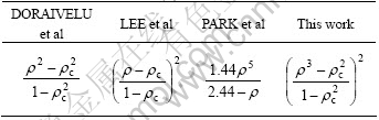
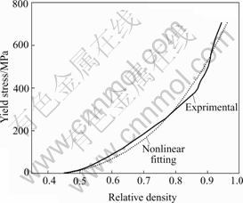
Fig.1 Comparison of nonlinear fitting and experimental results
In simulation, model parameters are set as Y0=740 MPa, elastic module E=200ρ3.2 kMPa and Poisson’s ratio  .
.
In experiments, iron powders were compacted to a cylindrical sample with a radius of 20 mm in a closed die at 130 ℃. An automatic powder pressing machine was used to conduct the compaction. During the deformation, the curve of the load versus the displacement was recorded by a microcomputer, which connected to the machine. Initially, the height of the cylinder was 70.27 mm. After pressing, the height was 30.82 mm. The volume of loose powder was measured and initial relative density was calculated to be  . Loose powder is quite easy to deform. Value of should be approximately equal to
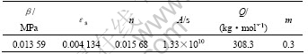
  . In this study, it was set at 0.404 9. Friction coefficient between powder and die wall was assumed to be 0.08. The strain hardening parameters are listed in Table 2.
Table 2 Strain hardening parameters in Eqns.(15) and (16)
The displacement vs load curves obtained from both experiments and simulation were compared in Fig.2.
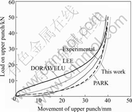
Fig.2 Load vs displacement curves of upper punch
3 User subroutine
The user subroutine flow charts were shown in Figs.3 and 4. The history variant needed in this subroutine includes the boundary stress ratio, elastic and shear module of prophase, plastic module, loading direction and flowing direction.
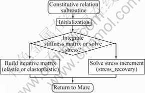
Fig.3 Flow chart of constitutive relation subroutine
4 Simulation
Warm compaction processing of a synchronous pulley was simulated. The schematic plot of the die, punches and powder is shown in Fig.5. The synchronous pulley illustrated in Fig.6 consists of four main parts: the gear part, inner-hole level, round arc level and cone level. Sizes of D1, D2 and D3 are 59 mm, 24 mm and 16 mm, respectively, and are kept constant during the compaction. Initially, H1 and H2 are 57 and 16 mm, respectively. After pressing, they become 28 and 10 mm, respectively. The initial relative density is 0.405.
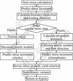
Fig.4 Flow chart of stress increment calculation
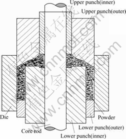
Fig.5 Sketch of cross section of die, punches and powder
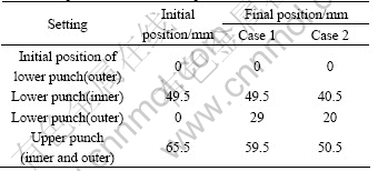
Two design cases were simulated. In both cases, the die and core rod were fixed. In the first case, the lower punch (inner) was fixed. The lower punch (outer) moved upward and two upper punches moved downward. In the second case, the lower punch (outer) moved upward while lower punch (inner) and the two upper punches moved downward. The displacements of each punch in these two cases are listed in Table 3. Velocites of the punches were proportional to the initial distances to their own final positions.
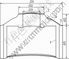
Fig.6 Sketch of synchronous pulley
Table 3 Displacement of different punches
The simulation was conducted on MSC.Marc. User subroutines were written and the flow stress model was implemented. Simulation of the two cases shared the same finite element model. Totally, 9 280 eight-node hexahedral elements and 2 960 nodes were included in the model. The calculation was divided into 100 increments steps. About an hour was spent on a PIV 2.4 GHz PC for each case.
Relative density distributions obtained in simulations for both cases are shown in Figs.7 and 8. In case 1, the highest relative density, 0.916, occurs at the bottom of the gear part (part 1 in Fig.6). The lowest relative density 0.827 occurs at the inner-hole part (part 2 in Fig.6) and the corner of cone level and the gear part (part 3 in Fig.6). In case 2, the highest relative density, 0.884, occurs at the bottom of gear part (part 1 in Fig.6) and the top of round arc level (part 4 in Fig.6). The lowest relative density 0.809 occurs at the middle of gear part (part 1 in Fig.6) and the corner of cone level and the gear part (part 3 in Fig.6). Comparing the two figures, density distribution in case 2 is much more homogeneous than that in case 1. Also, the low relative density area in case 2 is less than that of case 1. This contrast shows that the first case 1 is an improper movement design. In the filling stage of case 1, the initial position of lower punch (inner) was too low to get sufficient powder installed into parts 2 and 3. During compaction, the powder of part 4 was much easier to be densified than parts 2 and 3, so it was difficult for the powder of part 4 to flow transversely to parts 2 and 3.
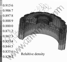
Fig.7 Relative density simulated in case 1
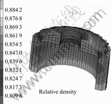
Fig.8 Relative density simulated in case 2
The simulation results of relative density distributions were compared with the experimental results. Fig.9 shows the relative density distribution on different part of the pulley. Fig.10 shows that the simulation prediction accords well with experimental results especially in parts 1 and 2. Fig.11 shows the cross section of P/M synchronous pulley developed by this work.
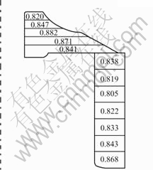
Fig.9 Distribution of experimental relative density
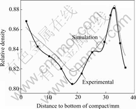
Fig.10 Comparison between simulated and experimental results of relative density vs distance to bottom of compact
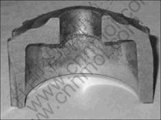
Fig.11 Cross section of synchronous pulley
5 Conclusions
1) The warm compaction constitutive equation of elliptical criterion was derived as

The flow stress model was determined through uniaxial warm compaction experiments.
2) The constitutive equations were integrated into the constitutive integral arithmetic. The model was implemented into MSC.Marc user subroutines to conduct the three dimensional numerical simulation of warm powder compaction.
3) The compaction process of a synchronous pulley was simulated. Relative density distribution results of two different cases were obtained and compared with those obtained from experiments. The simulation results show that the initial position and relative movements of the punches have great influence on the density of the green compacts.
References
[1] LI Y Y, NGAI T L, ZHANG D T, LONG Y, XIA W. Effect of die wall lubrication on warm compaction powder metallurgy[J]. Journal of Materials Processing Technology, 2002, 129(1-3): 354-358.
[2] NGAI Tungwai Leo, WANG Shang-lin, LI Yuan-yuan, ZHOU Zhao-yao, CHEN Wei-ping. Warm compaction powder metallurgy of Cu[J]. Trans Nonferrous Met Soc China, 2005, 15(1): 77-81.
[3] ZHOU Zhao-yao, ZHAO Wei-bin, CHEN Pu-qing, CHEN Wei-ping, SHAO Ming, WANG Jun-wen. Simulation of die wall friction effect on density distribution in metallic powder compaction[J]. Trans Nonferrous Met Soc China, 2002, 12(5): 890-893.
[4] LI Yuan-yuan, ZHANG Da-tong, XIAO Zhi-yu, NGAI Tungwai Leo. Influence of high-energy ball milling on Al-30wt%Si powder and ceramic particulate [J]. Trans Nonferrous Met Soc China, 2000, 10(3): 324-327.
[5] ZHOU Z Y, ZHAO W B, CHEN P Q, CHEN W P, SHAO M, WANG J W. Densification model for porous metallic powder materials[J]. Journal of Material Process Technology, 2002, 129(1-3): 385-388.
[6] LI Yuan-yuan, ZHANG Da-tong, NGAI Tungwai Leo, XIA Wei, LONG Yan. Diffusion couple between a high-strength wear-resisting aluminum bronze and machining tools materials [J]. Trans Nonferrous Met Soc China, 1999, 9(1): 6-10.
[7] SAUSA L C, SA J C. Finite element modeling of thermo mechanical forming processes using a mixed method [A]. Numerical Methods in Industrial Forming Processes[C]. A Balkena Rotterdam, 1992. 229-235.
[8] GREEN R J. A plasticity theory for porous solids[J]. Int J Mech Sci, 1972, 14: 215-224.
[9] KUHN H A, DOWNEY C L. Deformation characteristics and plasticity theory of sintered powder materials[J]. International Journal of Powder Metallurgy, 1971, 7(1): 15-25.
[10] SHIMA S, OYANE M. Plasticity theory for porous metals[J]. Int J Mech. Sci, 1976, 18: 285-292.
[11] Doraivelu S M. A new yield function for compressible P/M materials[J]. Int J of Mech Sci, 1984, 26(9/10): 527-535.
[12] FLECK N A, KUHN L T, MCMEEKING R M. Yielding of metal powder bonded by isolated contacts[J]. Journal of the Mechanics and Physics of Solids, 1992, 40: 1139-1162.
[13] GURSON A L. Continuum theory of ductile rupture by void nucleation and growth: part I―yield criteria and flow rules for porous ductile ductile media[J]. Journal of Engineering Materials and Technology, 1977, 99: 2-15.
[14] Redanz P. A study of stresses in powder compacted components during and after ejection[J]. International Journal of Solids and Structure, 2001, 38: 759-775.
[15] Redanz P, Tvergaard V. Analysis of shear band instabilities in compaction of powders[J]. International Journal of Solids and Structures, 2003, 40: 1853-1864.
[16] Bocchini G F. Warm compaction of metal powders: why it works, why it requires a sophisticated engineering approach[J]. Powder Metallurgy, 1999, 42(2): 171-180.
[17] Ariffin A K, Rahman M M, Muhamad N, Sahari J. Thermal-mechanical model for warm powder compaction process[J]. Journal of Materials Processing Technology, 2001, 116: 67-71.
[18] MSC Company. MSC.Marc 2000 User’s Guide[M]. Software Corporation, 2000. 255-257.
Foundation item: Project(50325516) supported by National Science Fund for Distinguish Young Scholars; Project(CG2003-GA005) supported by China Grid.
Corresponding author: ZHOU Zhao-yao; Tel: +86-20-87112933; E-mail: zhyzhou@scut.edu.cn
(Edited by LONG Huai-zhong)

