镍-铝-青铜合金表面类金刚石涂层的腐蚀性能和摩擦学行为
来源期刊:中国有色金属学报(英文版)2021年第2期
论文作者:Seyed Elias MOUSAVI Nastaran NAGHSHEHKESH Mohabbat AMIRNEJAD Hossein SHAMMAKHI Ali SONBOLI
文章页码:499 - 511
关键词:类金刚石涂层;镍-铝-青铜合金;摩擦学行为;耐腐蚀性能;纳米硬度;显微组织
Key words:diamond-like carbon coating; Ni-Al-bronze alloy; tribological behavior; corrosion resistance; nano- hardness; microstructure
摘 要:研究阴极电弧沉积制备的类金刚石(DLC)涂层对镍-铝-青铜(NAB)合金力学性能、摩擦学行为和腐蚀性能的影响。纳米硬度测试显示,与 NAB合金相比,DLC涂层具有更大的硬度。销盘摩擦测试显示,摩擦因数由NAB合金的0.2降低为DLC涂层的0.13。动电位极化和电化学阻抗谱结果表明,在3.5%(质量分数)的NaCl溶液中,腐蚀电流密度由NAB合金的2.5 μA/cm2降低到DLC涂层的0.14 μA/cm2。此外,基体-电解质界面的电荷转移电阻由NAB合金的3.3 kΩ・cm2提高到DLC涂层的120.8 kΩ・cm2,表明DLC涂层能提高合金的耐腐蚀性能。
Abstract: The effect of diamond-like carbon (DLC) coating (fabricated by cathodic arc deposition) on mechanical properties, tribological behavior and corrosion performance of the Ni-Al-bronze (NAB) alloy was investigated. Nano-hardness and pin-on-plate test showed that DLC coating had a greater hardness compared with NAB alloy. Besides, the decrease in friction coefficient from 0.2 for NAB substrate to 0.13 for the DLC-coated sample was observed. Potentiodynamic polarization and EIS results showed that the corrosion current density decreased from 2.5 μA/cm2 for bare NAB alloy to 0.14 μA/cm2 for DLC-coated sample in 3.5 wt.% NaCl solution. Moreover, the charge transfer resistance at the substrate-electrolyte interface increased from 3.3 kΩ・cm2 for NAB alloy to 120.8 kΩ・cm2 for DLC-coated alloy, which indicated an increase in corrosion resistance due to the DLC coating.
Trans. Nonferrous Met. Soc. China 31(2021) 499-511
Seyed Elias MOUSAVI1, Nastaran NAGHSHEHKESH1, Mohabbat AMIRNEJAD2, Hossein SHAMMAKHI1, Ali SONBOLI3
1. Department of Materials Engineering, Isfahan University of Technology, Isfahan 84156-83111, Iran;
2. Department of Materials Engineering, Babol Noshirvani University of Technology, Shariati Ave., Babol 47148-71167, Iran;
3. Department of Materials Engineering and Metallurgy, Faculty of Engineering, Arak University, Arak 3815688349, Iran
Received 19 February 2020; accepted 30 October 2020
Abstract: The effect of diamond-like carbon (DLC) coating (fabricated by cathodic arc deposition) on mechanical properties, tribological behavior and corrosion performance of the Ni-Al-bronze (NAB) alloy was investigated. Nano-hardness and pin-on-plate test showed that DLC coating had a greater hardness compared with NAB alloy. Besides, the decrease in friction coefficient from 0.2 for NAB substrate to 0.13 for the DLC-coated sample was observed. Potentiodynamic polarization and EIS results showed that the corrosion current density decreased from 2.5 μA/cm2 for bare NAB alloy to 0.14 μA/cm2 for DLC-coated sample in 3.5 wt.% NaCl solution. Moreover, the charge transfer resistance at the substrate-electrolyte interface increased from 3.3 kΩ・cm2 for NAB alloy to 120.8 kΩ・cm2 for DLC-coated alloy, which indicated an increase in corrosion resistance due to the DLC coating.
Key words: diamond-like carbon coating; Ni-Al-bronze alloy; tribological behavior; corrosion resistance; nano- hardness; microstructure
1 Introduction
Copper and its alloys are materials that are extensively used in marine, aerospace, petro- chemical and military industries [1,2]. Nickel- aluminum bronze (NAB) alloy with 9-12 wt.% aluminum as a major alloying element and up to 6 wt.% of iron and nickel, is one of the most widely used copper-based alloys [3,4]. A worthwhile combination of relatively high mechanical properties, acceptable corrosion resistance, and high resistance against cavitation damages and erosion- corrosion can be considered as desirable properties of these alloys [5,6]. These exclusive properties make these alloys applicable in marine industries, specifically for the construction of deck and connections in submarines and propellers, pumps, valves, and heat exchangers of the ships [3,5,7]. WHARTON et al [8] have reported that the main reason for high corrosion resistance of NAB alloys is the formation of a dense and adhesive protective layer which consists of both copper oxide and aluminum oxide. This protective layer is aluminum-rich adjacent to the substrate and copper-rich in the outer layer. However, pitting and stress corrosion cracking (SCC) are two deterioration mechanisms for NAB alloys in the chloride-containing environment (such as seawater), which normally initiate as a result of surface inhomogeneity such as second phase particles, inclusions, or selective dissolution of alloying elements [9]. On the other hand, many researchers have stated that in spite of the improvement of the protective film of the copper alloys in the flowing seawater, damage could occur to the protective film of the NAB alloys at flow velocities higher than a critical flow rate and severer turbulence conditions [10]. Therefore, applying a hard corrosion resistant coating is necessary for NAB alloys even with high corrosion resistance. In recent years, diamond-like carbon (DLC) coatings have received great attention from many researchers due to their diamond-like properties.
Amorphous carbon with a disordered carbon atoms network, which consists of both sp2 and sp3 electronic binding configuration of carbon atoms, is called diamond-like carbon [11]. The mechanical properties and corrosion performance of DLC coatings are essentially related to the relative fraction of component with sp2 hybridization in graphite and the component with sp3 hybridization of valence electrons in diamond [12]. Indeed, the mechanical, chemical, and electrical properties of DLC coatings preferably derive from the sp3 or diamond-like component of the film bonding [13]. Nowadays, DLC coatings have been used in the fields of cutting tools manufacturing [14], automobile parts [15], solar cells [16], implants [17], and artificial heart pumps [17,18] owing to the high hardness, appropriate corrosion resistance, thermal conductivity and acceptable electrical resistance, high resistance against wear, low friction coefficient and good biocompatibility.
A wide variety of deposition methods such as ion beam technique, physical vapor deposition (PVD) and chemical vapor deposition (CVD) have been used for applying DLC coating on different substrates [19-21]. Among these methods, applying at low temperatures makes PVD useful for deposition of DLC coating on nonferrous substrates. Low deposition temperature, can not only prevent phase transformation and grain growth of the coating, but also decrease the possibility of porosity formation. PVD also provides benefits such as good adhesion performance of the coating, the morphological and structural control, and the desirable mechanical and chemical properties of the coating [22].
DLC coatings have been successfully deposited on different kinds of substrates. YE et al [20] discussed the DLC coating effect on the tribocorrosion behavior of AISI 304 stainless steel. HADINATA et al [23] reported that DLC coating on carbon steel and brass substrates possesses more defects such as voids compared with stainless steel substrate. The gas barrier property of DLC thin film on polyethylene terephthalate (PET) has been investigated by RAY et al [24]. They showed that the barrier performance of DLC-coated PET is 10 times better than that of pristine PET. The above mentioned literature review shows that despite many studies that have been done to investigate the effect of DLC coating on many different substrates, there are no studies, to the best of our knowledge, about the influence of DLC coating on the wear and corrosion performance of NAB alloys.
In this study, DLC coating was applied to the Ni-Al-bronze alloy by the PVD method. Microhardness and reciprocating wear tests were performed to investigate the mechanical and tribological properties. The potentiodynamic polarization test and electrochemical impedance spectroscopy were used to study the corrosion behavior of coated alloy in 3.5 wt.% NaCl solution.
2 Experimental
2.1 Materials
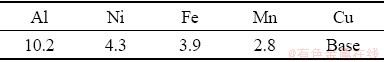
UNS C95500 alloy (ASTM B 763) specimens with dimensions of 15 mm × 50 mm × 5 mm were cut from as-cast Ni-Al-bronze alloy ingot. The chemical composition of substrate material is listed in Table 1.
Table 1 Chemical composition of substrate (wt.%)
2.2 Coating procedure
Before the physical vapor deposition process, the NAB substrates were ground with SiC sandpaper with grits of up to 600. The specimens were then polished, cleaned with alcohol, and degreased by acetone. To increase the adhesion of PVD coating to the substrate, the substrate was initially coated with a layer of chromium. Afterward, a thin layer of chromium carbide was applied as a secondary interlayer by cathodic arc evaporation (CAE) method using a 99.99% Cr target. The reactive gas mixture with C2H2:Ar ratio of 5:1 was introduced into the chamber, where the chromium carbide is formed by the reaction of chromium vapor with the ambient gaseous mixture and precipitates onto the surface. It should be noted that chromium carbide exhibits a good adhesion with both DLC topcoat and underneath the chromium layer. The cathodic arc deposition method was also used to apply DLC coating on the chromium carbide coated substrate in which a high purity graphite plate was used as a cathode. A DLC coating at approximately 3 μm-thickness was deposited under vacuum pressure of 0.3 Pa applied into the chamber. The substrate bias for DLC coating deposition was -0.4 kV in this study. During PVD, the substrate temperature was kept between 80 and 100 °C, and the deposition time was about 60 min.
2.3 Characterization
2.3.1 Raman spectroscopy
Raman spectroscopy as a non-destructive technique was performed at room temperature to investigate the functional change of the DLC coating using a Nicolet Dispersive Raman Spectrometer. The sample was excited by the 532 nm line of a Nd:YLF laser. The low input power of 30 mW was used to minimize any possible beam heating effects.
2.3.2 Microstructure observation
Microstructural investigations were conducted using an Olympus optical microscope and Philips XL30 scanning electron microscope (SEM) equipped with an energy dispersive X-ray spectrometer (EDS). For the NAB substrate microstructural studies, metallographic samples were prepared by SiC sandpaper grinding up to 2000 grit, followed by mechanical polishing to a mirror finish using 0.3 μm alumina. The samples were then cleaned with acetone and dried with alcohol. Ferric chloride solution (5 g FeCl3, 100 mL methanol, and 5 mL HCl) was used as a chemical etchant for the microscopic evaluations. The morphological features of DLC coating and elemental composition were investigated in more detail by SEM/EDS.
2.3.3 Nano-hardness test
To investigate the hardness variations from the substrate toward the coating, Koopa nano-hardness tester model MH3 was used. Using an applied load of 3 N for 20 s dwell, a set of five hardness measurements on the polished cross-section of the coated sample were obtained over a 500 nm distance perpendicular to the substrate-coating interface. The average value of hardness with associated standard deviation was calculated for any specified distance.
2.3.4 Wear test
Reciprocating pin on plate wear test was accomplished in unlubricated conditions and ventilated air (25-30 °C, 40%-50% of relative humidity) to evaluate the tribological behavior of NAB substrate and DLC coating. The test was done using an AISI 52100 (UNS G52986) bearing steel pin (bulk harness of HRC 64) with a diameter of 5 mm and an applied load of 15 N. Linear sliding speed of pin was equal to 0.1 mm/min for a total sliding distance of 300 m. the progression of wear test was scrutinized by interruption of test at specific intervals. At each interval (the measured distance was equal to 50 m), the sample was removed, cleaned with alcohol, dried, and weighed using a balance with an accuracy of 0.1 mg to measure the mass loss caused by wear. It should be noted that for each interval, the difference in measured mass and the initial mass of the sample was considered as a mass loss.
2.3.5 Electrochemical measurements
Potentiodynamic polarization and electro- chemical impedance spectroscopy (EIS) techniques were used to assess the corrosion performance of the NAB substrate and DLC-coated sample. All electrochemical tests were performed in a 3.5 wt.% NaCl solution at room temperature using AMETEK Parstat 2273 potentiostat. A conventional three- electrode cell with a saturated calomel electrode (SCE, 0.244 V versus SHE at 25 °C) as a reference electrode, the platinum sheet as an auxiliary electrode, and a working electrode (sample) was used. The surface area of all samples exposed to corrosion was 0.6 cm2. The NAB substrate and DLC coating samples were immersed in a 3.5 wt.% NaCl solution for 60 min until the open circuit potential (OCP) reached a plateau value. The potentiodynamic polarization tests were conducted from -250 mV (versus OCP) to 1250 mV (versus OCP) with a scan rate of 1 mV/s. Tafel extrapolation method was used to calculate the corrosion parameters of samples. The coating porosity was assessed from the obtained electrochemical parameters by the experimental equation [25]:
 (1)
(1)
where P is the total coating porosity, RP is the polarization resistance of the coated sample, RPS is the polarization resistance of substrate, Δφcorr is the potential difference between corrosion potential of the substrate and coated alloy, and βa is the anodic Tafel slope for the substrate. Additionally, the corrosion protective efficiency (Pe) was measured from polarization curves using the following equation [26]:
 (2)
(2)
where Jcorr and  are the corrosion current densities of the coated sample and bare substrate, respectively.
The electrochemical impedance spectroscopy (EIS) measurements were done at open circuit potential with a sinusoidal wave of 10 mV in amplitude. The frequency range used for the electrochemical impedance spectroscopy tests was from 0.1 Hz to 100 kHz. The EIS spectra were illustrated using a typical Nyquist plot in which the imaginary part of impedance (ZIm) has been plotted versus real part of impedance (ZRe). The Nyquist plots were analyzed with ZView software to calculate the electrochemical parameters of the corresponding equivalent circuit.
3 Results and discussion
3.1 Raman spectroscopy
One of the best vibrational spectroscopic technique used to provide structural details by which molecules and chemical structures can be identified is Raman spectroscopy. Figure 1 shows the Raman spectrum of the DLC coating, which was fitted to two Lorentzian peaks. As can be seen, the Raman spectrum of DLC coating reveals two peaks at 1348 and 1560 cm-1 related to D and G bands of carbon atoms, respectively [27]. It should be mentioned that carbon atoms could form bonds by mixing different molecular orbitals to hybrid orbitals such as sp2 and sp3 hybridization. Diamond-like properties are related to the bond-angle disorder in sp3 configuration in which four valence electrons of carbon make a strong σ bond with electrons of the adjacent atom. On the other hand, sp2 hybridization displays graphite structure wherein in addition to three s bonds, the hybridized atomic configuration of carbon atoms possesses one π bond, which has weaker strength in comparison with σ bond [28]. The combination of sp3 (diamond-like structure) and sp2 (graphite-like structure) bonds will lead to a variety of desired properties in carbon materials such as DLC coatings. The dense diamond-like structure has an important role in increasing yield strength, adhesion, and improving chemical and corrosion properties. On the other hand, the graphite-like structure, by its weaker strength, leads to an increase in toughness [29].
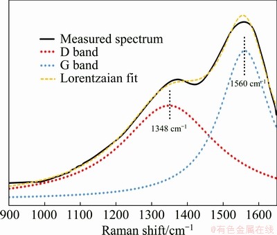
Fig. 1 Deconvoluted Raman spectrum of DLC coating
In visible Raman spectroscopy (exciting by the 532 nm line of a Nd:YLF laser in this study), the D and G peaks correspond to sp2 configuration. The G band is related to the stretching mode of the C―C single bond of all pairs of sp2 atoms in both rings and chains, whereas the D band is caused by breathing mode of carbon rings. This indicates that if there is no ring in the structure, the D peak will not be observed in Raman spectrum. It should be noted that the C―C sp3 vibration can only be seen at ultraviolet excitations [30]. FERRARI and ROBERTSON [31] have developed a model based on which the sp3 configuration content can be determined from the G peak position in Raman spectrum and the ratio of D peak integrated intensity to G peak integrated intensity (I(D)/I(G)). The calculated ratio of I(D)/I(G) was 1.19, which corresponds to the disorder extent of the structure. Based on the model presented by FERRARI and ROBERTSON [31], the DLC coating in this study contains approximately 18% sp3 configuration. DALIBON et al [28] have reported that DLC coating on martensitic stainless steel fabricated by plasma assisted chemical vapor deposition with D and G peaks positions at 1368 and 1546 cm-1, respectively, and I(D)/I(G) ratio equal to 0.48, includes about 20% sp3 configuration. A similar result has been reported by ZOU et al [32], that the DLC coating deposited on AZ91 magnesium alloy contains 24%-34% sp3 atoms.
3.2 Microstructure
Figure 2 shows the microstructure of the NAB substrate. As shown in Fig. 2, the bright contrast α phase was observed to be the predominant phase. This phase is a copper-rich phase with FCC crystalline structure. In addition, the microstructure consists of dark contrast β′ (martensitic β) phase between α grains, and several κ phases. κIII phase is the lamellar eutectoids in between α phase and mainly composed of nickel aluminide (NiAl) [5]. The continuous lamellar morphological features of the κIII phase lead to the formation of micro galvanic cells, which accelerates the corrosion reactions. However, this effect can be neglected for the NAB alloy used in this study due to the very low volume fraction of κIII phase. On the other hand, the κIV phase could be seen as a fine precipitate within α grains with an iron aluminide (Fe3Al) composition, which will not cause corrosion problems because of its fine discontinuous morphology [33].
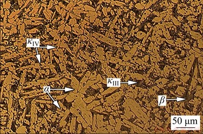
Fig. 2 Microstructure of as-cast NAB substrate obtained by optical microscope
More-detailed insight into the surface morphology of DLC coating was discerned by scanning electron microscopy (SEM), as shown in Fig. 3, where the morphological features of DLC coating has been illustrated via the secondary electron micrograph. Secondary electron microscopy is generally used for imaging the surface of a structure. As can be seen in Fig. 3, the DLC coating was deposited uniformly over Ni-Al- bronze alloy surface; however, pores of different sizes are observed in the DLC coating structure. It should be noted that the DLC coating porosities establish easy paths for aggressive ions and corrosive chemicals to attack the NAB substrate materials. Additionally, the DLC layer surface was rough, which could be due to the uneven surface of the deposited chromium carbide interlayer. Furthermore, morphological investigations revealed the presence of white particles on the surface of deposited DLC film. The chemical composition of white particles was determined by EDS analysis, which revealed that these particles are rich in chromium (see Fig. 4).
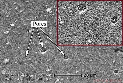
Fig. 3 Secondary electron micrograph showing DLC coating porosities
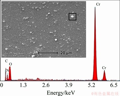
Fig. 4 SEM micrograph of DLC coating surface showing the presence of white particles and corresponding EDS analysis
As mentioned above, before the final DLC coating deposition, chromium and chromium carbide thin layers were applied on the surface as intermediate layers. These white regions probably correspond to the intermediate layers where the final DLC coating did not properly cover the surface. The microstructure of deposited coating at chromium-rich areas is depicted in Fig. 5 by SEM observations at a high magnification. As can be observed, the discontinuity regions are visible just around the Cr-rich particles. The different chemical affinity or adhesion strength of the DLC coating to either Cr-rich particles or the DLC coating itself may cause such discontinuities and coating defects [34].
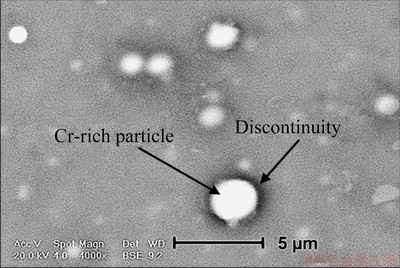
Fig. 5 SEM micrograph of white particles present on surface
Coating porosities and circumferential discontinuities around Cr-rich particles can enhance the diffusion rate of corrosive spices toward the substrate. DLC coatings are chemically inert, which makes them promising materials as corrosion- protection coatings. This coating increases the corrosion resistance by creating a barrier layer between the NAB substrate and the corrosive environment. The presence of pores and discontinuities in the coating allow the corrosive environment to easily penetrate the film and increase the corrosion rate by reaching the substrate surface. ZENG et al [35] reported that the DLC coatings porosities can cause a rapid dissolution of the substrate due to the nobler electrochemical
behavior of DLC coating compared to the substrate.
The effects of coating defects on mechanical properties and corrosion performance of DLC coating are described later in this research.
3.3 Nano-hardness
Figure 6 displays the nano-hardness profile of the DLC-coated sample. As seen, the NAB substrate hardness is about 2.5 GPa, whereas the nano-hardness of DLC coating is varied in the range of 20-22 GPa that is approximately ten times greater than that of NAB substrate. The greatest hardness value of 24 GPa at 500 nm distance from the NAB surface may be attributed to the hard chromium carbide interlayer. The drastic increase in hardness after applying the DLC coating can be primarily ascribed to the diamond-like structure of coating with sp3 configurations. It is worth mentioning that in sp3 hybridization, four equivalent hybridized orbitals can establish C―C σ bonds with high bonding energy when the sp3 orbitals of adjacent carbon atoms overlap. The presence of strong σ bonds leads to high hardness of sp3 configuration in comparison with sp2 one. The effect of sp3 content on the physical, mechanical, and chemical properties of amorphous carbon films have been described in detail elsewhere [36].
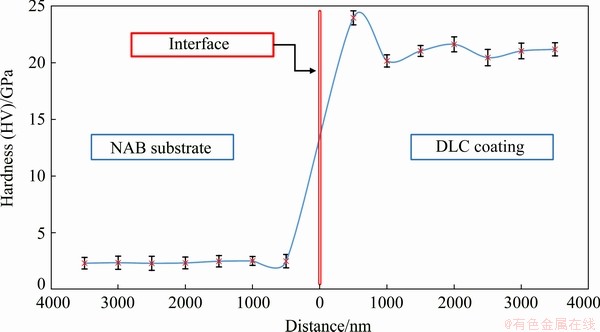
Fig. 6 Nano-hardness variation across cross-section of DLC-coated sample
Applying DLC coating in the absence of hydrogen can be another important factor for high hardness values. The effects of cathodic arc deposition parameters on sp3 content of DLC coatings and subsequent hardness values have been investigated by many researchers [21,30]. There is a broad agreement that a higher sp3/sp2 ratio will result in the formation of DLC coating with greater hardness values [12]. However, this is not the case for hydrogenated DLC coatings. KAYANI et al [37] have reported that atomic hydrogen promotes the formation of sp3 configuration with strong s bonds via passivation of dangling bonds. On the other hand, high hydrogen concentration increases the number of C―H bonds, which relaxes the stress and decreases the DLC coating’s hardness.
3.4 Wear resistance
Variations of mass loss due to wear as a function of sliding distance under the load of 15 N were plotted in Fig. 7 for NAB substrate and DLC coating. The curves of linear behavior of mass loss vs sliding distance indicate the steady-state wear rate (defined as mass loss of samples divided by the sliding distance) of both NAB substrate and DLC coating samples. The wear rates of both samples were measured from the slope of mass loss vs sliding distance curves. Despite the almost linear wear behavior of both samples, a linear regression method was used for more accurate calculation. The wear rate of DLC coatings was computed as 0.0031 mg/m compared with 0.0200 mg/m for that of NAB substrate. The results revealed that applying DLC coating leads to decreasing the wear rate by a factor of 6, which confirmed the improvement of the sample’s wear resistance after coating.
The friction coefficient variation of NAB substrate and DLC coating prepared by cathodic arc deposition method is shown as a function of sliding distance in Fig. 8.
It can be seen that the overall friction coefficient of DLC coating is lower than that of the NAB substrate at each specified sliding distance.
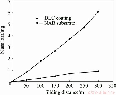
Fig. 7 Mass loss of NAB substrate and DLC coating as function of sliding distance
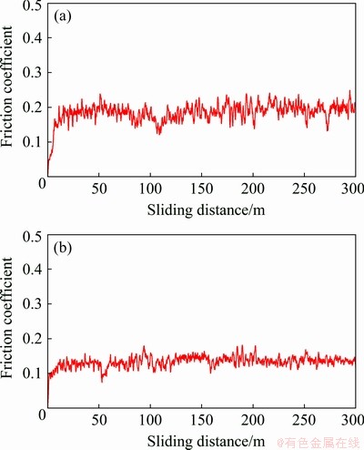
Fig. 8 Friction coefficient versus sliding distance for NAB substrate (a) and DLC coating (b)
The average friction coefficients after 300 m sliding distance were equal to 0.18 and 0.13 for NAB substrate and DLC coating, respectively. Enhanced wear properties of the DLC-coated sample may be ascribed, as described by many researchers [12,38], to the greater hardness values of DLC coating (~20 GPa) in comparison with NAB substrate (~2.5 GPa). It must be remembered that based on the Archards’ model [39], the wear rate is inversely proportional to the hardness of material. Besides, ZOU et al [32] have reported that the friction process of DLC coatings involves the formation of a transfer layer with an amorphous graphite-like carbon structure. There is a perception that the transfer layer is formed via a friction-assisted phase transformation of the surface layer of DLC coating and acts as a lubricant on the coating surface. Indeed, the great hardness values of DLC coating in cooperation with the self-lubricating mechanism due to the transfer layer formation are two major reasons for low friction coefficient of DLC coating in comparison to the NAB substrate. It should be noted that in the case of applying DLC coatings with higher surface smoothness and lower porosities, a much lower coefficient of expansion can be obtained.
As depicted in Fig. 8(a), at the beginning of the NAB substrate wear test, the friction coefficient goes through the run-in period for approximately 20 m sliding distance after some time reaches its approximate steady-state. At the same time, this is not the case for DLC coating (see Fig. 8(b)). The increase in friction coefficient at the early stage of wear test can be assigned to the oxidation of wear debris as a result of friction-induced shear [21]. It should be noted that the oxidation of wear debris would result in increased adhesion in interfacial areas. On the other hand, with increasing the sliding distance from 40 to 110 m, a slight decreasing trend of friction coefficient of NAB substrate is visible, followed by a further increasing trajectory. The local maximum value of NAB substrate friction coefficient may be attributed to the highly adhesive contact between the pin and NAB surface, which increases the friction force of sliding motion [40]. With increasing sliding distance, the first layer will remove from the NAB surface, the worn surface will gradually be smoother, and as a result, the friction coefficient will be decreased. At this point, greater friction forces will be needed to overcome the surface atomic bonds. Consequently, the friction coefficient will be increased. These processes will be periodically repeated until the complete failure of the sample.
In addition, the oscillation of friction coefficient for the NAB substrate is larger than that of DLC coating. The large oscillation of friction coefficient may be attributed to the periodical accumulation and omission of wear debris on the worn route, as stated by MAHMOUD et al [40].
It has been confirmed that in our previous study [41] the wear surface of NAB alloy after sliding wear tests was covered with grooves parallel to sliding direction, indicating the contribution of the abrasive wear mechanism. Moreover, the micrograph shows deep carvings on the surface which may be caused by detachment of the particles. This wear mechanism, along with easy shear of NAB substrate, will result in severe mass loss during wear test (Fig. 7) as well as low friction coefficient. The results indicated that the DLC coating could greatly improve the wear properties of NAB alloy.
3.5 Corrosion resistance
3.5.1 Potentiodynamic polarization
Figure 9 displays the potentiodynamic polarization curves of the as-cast NAB substrate and DLC-coated sample in 3.5 wt.% NaCl solution and the deduced electrochemical parameters calculated from polarization curves are summarized in Table 2.
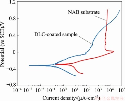
Fig. 9 Polarization behavior of bare NAB substrate and DLC-coated sample in 3.5 wt.% NaCl solution
As depicted in Fig. 9, the NAB substrate shows the anode passivation phenomenon, but this is not the case for the DLC-coated sample. For the bare NAB substrate, the active dissolution process occurs in the potential range from corrosion potential to about 0 V (vs SCE). In this range, the current density is proportional to the potential. As the potential increases from 0 V (vs SCE), the current density decreases to a certain value (Jpass=4.2 mA/cm2) and does not change with a further increase in potential. The passivation phenomenon for NAB alloy in 3.5 wt.% NaCl solution is associated with the formation of a stable protective film on the surface during corrosion. This protective film is 900-1000 nm in thickness, which is composed of both aluminum and copper oxides with Cu2O in outer regions and Al2O3 in adjacent the base metal [7,8].
Table 2 Electrochemical parameters of samples
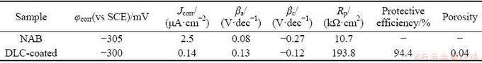
According to Fig. 9 and Table 2, the DLC coating increases the polarization resistance from 10.7 kΩ・cm2 for bare NAB substrate to 193.8 kΩ・cm2 for DLC-coated sample. The lower corrosion resistance in addition to the higher corrosion current density of bare NAB substrate (Jcorr=2.5 μA/cm2) is detectable in comparison with DLC-coated sample with corrosion current density of 0.14 μA/cm2. Furthermore, the cathodic Tafel slope for the NAB substrate polarization curve, i.e., -0.27 V/dec, is higher than that of DLC-coated sample, i.e., -0.12 V/dec. The higher cathodic Tafel slope of NAB substrate is mainly due to the fast cathodic reduction kinetics. It seems that DLC coating acts as a barrier layer against corrosion because of low porosity and proper adhesion of DLC coating to the substrate. The coating prevents corrosive species such as chloride ions and oxygen molecules from reaching the substrate surface and as a result, the corrosion rate will be decreased. The protective efficiency and total coating porosity of DLC coating on NAB substrate in 3.5 wt.% NaCl solution calculated from corrosion current density were 94.4% and 0.04, respectively. This result corroborates with another research by MANHABOSCO and MüLLER [42], wherein the DLC coating fabricated on Ti6Al4V alloy possesses a protective efficiency of about 97% and a porosity of 0.01. It should be emphasized that the coating porosity, even to a low extent, is responsible for diffusion of corrosive species through the coating and subsequent local corrosion, coating blistering, and delamination. A schematic illustration of corrosion system for DLC-coated NAB alloy is shown in Fig. 10.
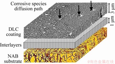
Fig. 10 Schematic representation of corrosion behavior of DLC-coated sample in 3.5 wt.% NaCl solution
As can be seen in Fig. 10, the interlayer can play an important role in protecting the NAB substrate. The aggressive corrosion agents could pass through the coating porosities and reach the interlayer. As a result, the chromium carbide interlayer will be oxidized, and the formation of oxide film as a physical barrier layer could prevent the dissolution of the NAB substrate [20]. On the other hand, the chromium carbide interlayer can improve the adhesion of DLC coating on the NAB substrate, which led to a decrease in corrosion rate of NAB substrate. The results show that the hard DLC coating with low porosity along with a chromium carbide thin film as an adhesive interlayer increases the wear resistance of the coated sample. On the other hand, the low porosity of these coatings and the presence of the chromium-based interlayer will increase the corrosion resistance in 3.5 wt.% NaCl solution by forming a barrier layer.
3.5.2 Electrochemical impedance spectroscopy (EIS)
The electrochemical impedance spectroscopy is one of the prevalent non-destructive techniques, which can be used to determine the corrosion mechanisms involved in a corroding system.
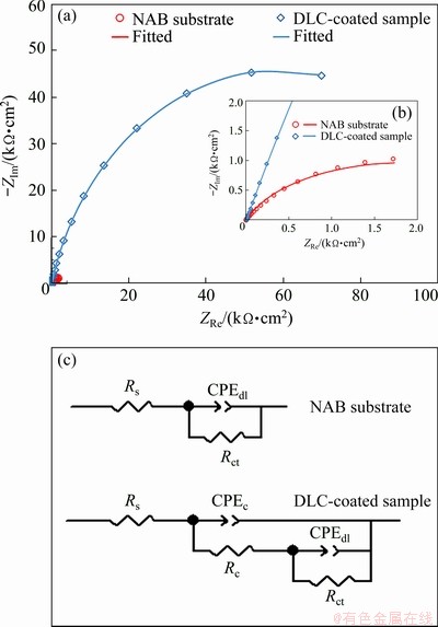
Fig. 11 Nyquist plots (a), enlarged Nyquist plots together with corresponding fitted curves for bare NAB substrate and DLC-coated sample (b), and equivalent circuit related to NAB substrate and DLC-coated sample (c)
Typical Nyquist impedance diagram and fitted curves are presented in Fig. 11(a), in which a good agreement between experimental results and calculated data can be observed. The greater diameter of the semicircle in Nyquist plot of DLC-coated sample as compared to that of NAB substrate (see Fig. 11(b)) indicates that the overall impedance of the coated sample is greater than that of bare substrate. It can be said that the presence of DLC coating leads to better protection in 3.5 wt.% NaCl solution. In conformity with corrosion processes on the surface of a coated system, two- time constants are usually utilized to identify a coated system [43], whereas the bare NAB alloy routinely shows one time constant [10]. Figure 11(c) represents the one-time constant equivalent circuit and two-time constant equivalent circuit for the bare NAB alloy and coated sample, respectively. Here, Rs is the uncompensated solution resistance between the working electrode and reference electrode, Rct is the charge transfer resistance, which indicates the amount of resistance against the corrosion reaction at the substrate-solution interface, and Rc is related to the resistance to ionic conduction path in the coating. As well, there are two constant phase elements or CPE’s: CPEdl is the double-layer capacitance, and CPEc is the coating-capacitive nature. It is worth noting that a CPE reflects the heterogeneous nature of the solid electrode interface due to microscopic surface roughness and surface defects, which behaves as a non-ideal frequency-independent capacitor [26]. The impedance (ZCPE) of a CPE has the following form:
ZCPE=1/Y0(jω)n (3)
where Y0 is the admittance constant, j is the imaginary unit, ω is the radial frequency (ω=2πf) of AC voltage, and n is the exponent of CPE ranging from 0 for a pure resistance to 1 for a pure capacitance behavior of CPE [19].
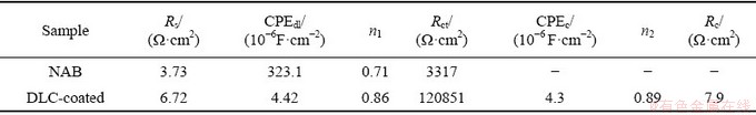
Circuit electrochemical parameters acquired from the fitting of EIS spectra to the electrical equivalent circuits from Fig. 11(c) are listed in Table 3. The chi-square goodness of fit values (χ2) were 0.010 and 0.001 for bare NAB substrate and DLC-coated sample, respectively.
The solution resistance values increased from 3.73 Ω・cm2 for NAB substrate to 6.72 Ω・cm2 for DLC-coated sample. It can be attributed to the increase in corrosion resistance of the sample due to the presence of DLC coating, which decreases ion dissolution from the substrate to electrolyte. Additionally, the results show that the Rct of DLC-coated sample (i.e., 120851 Ω・cm2) is larger than that of bare NAB substrate, illustrating the higher corrosion resistance of DLC-coated sample, which is in agreement with potentiodynamic polarization results. As stated by DING et al [7], an oxide passivation layer can form on the surface of bare NAB alloy, which gives rise to a relatively high Rct at the substrate-electrolyte interface. However, the dissolution of passive layer, along with the porosities that may be present in the passivation layer structure, leads to the low values of Rct [8]. As well, the double-layer capacitance (CPEdl) of coated sample was about 4.42×10⁻⁶ F/cm2 with n1=0.86, which confirmed the presence of a relatively compact barrier layer on the NAB substrate. It should be noted that the CPEc in the coated sample reveals the diffusion of the species along with the coating layer. There may be the diffusion of the chloride ions from electrolyte to the coating, which controls the corrosion behavior. The DLC coating with a chromium carbide interlayer inserted results in greater protective efficiency due to effectively preventing the corrosive species from penetrating towards the NAB substrate. Similar results have been reported by others [44].
Table 3 EIS fitting parameters of bare NAB substrate and DLC-coated sample
4 Conclusions
(1) Nano-hardness results showed that applying the coating causes a dramatic increase in hardness by one order of magnitude.
(2) Significant increase in tribological behavior of the alloy was obtained by applying the coating; in such a way that in reciprocating wear test under loading of 15 N limited mass loss was observed. Moreover, the average friction coefficient of coating was equal to 0.13, which was lower than that of the substrate, which was 0.2.
(3) Polarization diagrams showed that DLC coating could decrease the corrosion current density of the sample in 3.5 wt.% NaCl solution from 2.5 μA/cm2 for bare NAB alloy to 0.14 μA/cm2 for DLC-coated sample. In addition, the polarization resistance increases by almost twenty times due to the presence of DLC coating.
(4) EIS spectra and fitted parameters revealed that the charge transfer resistance increased to a great extent as a result of DLC coating. Furthermore, from the capacitance behavior of coating with n=0.89, it was demonstrated that the DLC coating with chromium carbide interlayer could effectively act as barrier layers preventing the penetration of corrosive species toward the substrate.
References
[1] MOUSAVI S E, SONBOLI A, NAGHSHEHKESH N, MERATIAN M, SALEHI A, SANAYEI M. Different behavior of alpha and beta phases in a low stacking fault energy copper alloy under severe plastic deformation [J]. Materials Science and Engineering A, 2020, 788: 139550.
[2] MOUSAVI S E, NAGHSHEKESH N, AHMADI F, SADEGHI B, CAVALIERE P. Effect of lead on the crack propagation and the mechanical properties of Brass processed by ECAP at different temperatures [J]. Materials Science and Engineering A, 2018, 728: 231-238.
[3] MOUSSA M E, WALY M A, AMIN M. Effect of high intensity ultrasonic treatment on microstructural modification and hardness of a nickel-aluminum bronze alloy [J]. Journal of Alloys and Compounds, 2018, 741: 804-813.
[4] MOUSAVI S E, MERATIAN M, REZAEIAN A. Investigation of mechanical properties and fracture surfaces of dual-phase 60--40 brass alloy processed by warm equal-channel angular pressing [J]. Journal of Materials Science, 2017, 52: 8041-8051.
[5] LV Y, WANG L, HAN Y, XU X, LU W. Investigation of microstructure and mechanical properties of hot worked NiAl bronze alloy with different deformation degree [J]. Materials Science and Engineering A, 2015, 643: 17-24.
[6] XU X, WANG H, LV Y, LU W, SUN G. Investigation on deformation behavior of nickel aluminum bronze by neutron diffraction and transmission electron microscopy [J]. Metallurgical and Materials Transactions A: Physical Metallurgy and Materials Science, 2016, 47: 2081-2092.
[7] DING Y, LV Y, CHEN K, ZHAO B, HAN Y, WANG L, LU W. Effects of microstructure on the stress corrosion cracking behavior of nickel-aluminum bronze alloy in 3.5% NaCl solution [J]. Materials Science and Engineering A, 2018, 733: 361-373.
[8] WHARTON J A, BARIK R C, KEAR G, WOOD R J K, STOKES K R, WALSH F C. The corrosion of nickel- aluminium bronze in seawater [J]. Corrosion Science, 2005, 47: 3336-3367.
[9] PIDAPARTI R M, AGHAZADEH B S, WHITFIELD A, RAO A S, MERCIER G P. Classification of corrosion defects in NiAl bronze through image analysis [J]. Corrosion Science, 2010, 52: 3661-3666.
[10] SONG Q N, ZHENG Y G, NI D R, MA Z Y. Characterization of the corrosion product films formed on the as-cast and friction-stir processed Ni-Al bronze in a 3.5 wt% NaCl solution [J]. Corrosion, 2015, 71: 606-614.
[11] FARALDI F, ANGELINI E, RICCUCCI C, MEZZI A, CASCHERA D, GRASSINI S. Innovative diamond-like carbon coatings for the conservation of bronzes [J]. Surface and Interface Analysis, 2014, 46: 764-770.
[12] VETTER J. 60 years of DLC coatings: Historical highlights and technical review of cathodic arc processes to synthesize various DLC types, and their evolution for industrial applications [J]. Surface and Coatings Technology, 2014, 257: 213-240.
[13] BHARATHY P V, YANG Q, KIRAN M S R N, RHA J J, NATARAJ D, MANGALARAJ D. Reactive biased target ion beam deposited W-DLC nanocomposite thin films- Microstructure and its mechanical properties [J]. Diamond and Related Materials, 2012, 23: 34-43.
[14] ARTINI C, MUOLO M L, PASSERONE A. Diamond-metal interfaces in cutting tools: A review [J]. Journal of Materials Science, 2012, 47: 3252-3264.
[15] HOLMBERG K, ANDERSSON P, ERDEMIR A. Global energy consumption due to friction in passenger cars [J]. Tribology International, 2012, 47: 221-234.
[16] ISMAIL R A, MOUSA A M, HASSAN M A, HAMOUDI W K. Synthesis of diamond-like carbon films by electro- deposition technique for solar cell applications [J]. Optical and Quantum Electronics, 2016, 48: 1-11.
[17] PENKOV O V, KHERADMANDFARD M, KHADEM M, KHARAZIHA M, MIRZAAMIRI R, SEO K J, KIM D E. Ion-beam irradiation of DLC-based nanocomposite: Creation of a highly biocompatible surface [J]. Applied Surface Science, 2019, 469: 896-903.
[18] ALANAZI A S. Medical application of diamond-like carbon (DLC) coating―A review [J]. International Journal of Clinical & Medical Informatics Review Article, 2018, 1: 74-82.
[19] LIU Z H, ZHAO J F, McLAUGHLIN J. A study of microstructural and electrochemical properties of ultra-thin DLC coatings on AlTiC substrates deposited using the ion beam technique [J]. Diamond and Related Materials, 1999, 8: 56-63.
[20] YE Y, WANG Y, MA X, ZHANG D, WANG L, LI X. Tribocorrosion behaviors of multilayer PVD DLC coated 304L stainless steel in seawater [J]. Diamond and Related Materials, 2017, 79: 70-78.
[21] JOKARI-SHESHDEH M, MAHBOUBI F, DEHGHANI K. Structure and tribological behavior of diamond-like carbon coatings deposited on the martensitic stainless steel: The influence of gas composition and temperature [J]. Diamond and Related Materials, 2018, 81: 77-88.
[22] BAPTISTA A, SILVA F, PORTEIRO J, MIGUEZ J, PINTO G. Sputtering physical vapour deposition (PVD) coatings: A critical review on process improvement and market trend demands [J]. Coatings, 2018, 8: 402.
[23] HADINATA S S, LEE M T, PAN S J, TSAI W T, TAI C Y, SHIH C F. Electrochemical performances of diamond-like carbon coatings on carbon steel, stainless steel, and brass [J]. Thin Solid Films, 2013, 529: 412-416.
[24] RAY S C, MUKHERJEE D, SARMA S, BHATTACHARYA G, MATHUR A, ROY S S, MCLAUGHLIN J A. Functional diamond like carbon (DLC) coatings on polymer for improved gas barrier performance [J]. Diamond and Related Materials, 2017, 80: 59-63.
[25] MATTHES B, BROSZEIT E, AROMAA J, RONKAINEN H, HANNULA S P, LEYLAND A, MATTHEWS A. Corrosion performance of some titanium-based hard coatings [J]. Surface and Coatings Technology, 1991, 49: 489-495.
[26] SYED J A, LU H, TANG S, MENG X. Enhanced corrosion protective PANI-PAA/PEI multilayer composite coatings for 316SS by spin coating technique [J]. Applied Surface Science, 2015, 325: 160-169.
[27] ZHENG Xin-ying, ZHANG Ya-rong, ZHANG Bao-rong. Effect of N-ion implantation and diamond-like carbon coating on fretting wear behaviors of Ti6Al7Nb in artificial saliva [J]. Transactions of Nonferrous Metals Society of China, 2017, 27: 1071-1080.
[28] DALIBON E L, BRüHL S P, TRAVA-AIROLDI V J, ESCALADA L, SIMISON S N. Hard DLC coating deposited over nitrided martensitic stainless steel: Analysis of adhesion and corrosion resistance [J]. Journal of Materials Research, 2016, 31: 3549-3556.
[29] MCDONALD D T, BARR C J, XIA K. Effect of equal channel angular pressing on lamellar microstructures in nickel aluminum bronze [J]. Metallurgical and Materials Transactions A: Physical Metallurgy and Materials Science, 2013, 44: 5556-5566.
[30] HE M, YEO C. Evaluation of thermal degradation of DLC film using a novel Raman spectroscopy technique [J]. Coatings, 2018, 8: 1-10.
[31] FERRARI A C, ROBERTSON J. Raman spectroscopy of amorphous, nanostructured, diamond-like carbon, and nanodiamond [J]. Philosophical Transactions of the Royal Society A: Mathematical, Physical and Engineering Sciences, 2004, 362: 2477-2512.
[32] ZOU Y S, WU Y F, YANG H, CANG K, SONG G H, LI Z X, ZHOU K. The microstructure, mechanical and friction properties of protective diamond like carbon films on magnesium alloy [J]. Applied Surface Science, 2011, 258: 1624-1629.
[33] ZHAO B, LV Y, DING Y, WANG L, LU W. The grain refinement mechanisms of various phases in shot-peened nickel-aluminum bronze (NAB) alloy [J]. Materials Characterization, 2018, 144: 77-85.
[34] VERESCHAKA A A, GRIGORIEV S N. Study of cracking mechanisms in multi-layered composite nano-structured coatings [J]. Wear, 2017, 378: 43-57.
[35] ZENG A, LIU E, ANNERGREN I F, TAN S N, ZHANG S, HING P, GAO J. EIS capacitance diagnosis of nanoporosity effect on the corrosion protection of DLC films [J]. Diamond and Related Materials, 2002, 11: 160-168.
[36] YEO R J. Ultrathin carbon-based overcoats for extremely high density magnetic recording [M]. Springer, 2017.
[37] KAYANI A, MOORE A, NANDASIRI M I, ALFAIFY S, GARRATT E, INGRAM D, MAQBOOL M. Effect of bias and hydrogenation on the elemental concentration and the thermal stability of amorphous thin carbon films, deposited on Si substrate [J]. Diamond and Related Materials, 2009, 18: 1333-1337.
[38] LUBWAMA M, CORCORAN B, SAYERS K, KIRABIRA J B, SEBBIT A, MCDONNELL K A, DOWLING D. Adhesion and composite micro-hardness of DLC and Si-DLC films deposited on nitrile rubber [J]. Surface and Coatings Technology, 2012, 206: 4881-4886.
[39] ARAUJO P, CHICOT D, STAIA M, LESAGE J. Residual stresses and adhesion of thermal spray coatings [J]. Surface Engineering, 2005, 21: 35-40.
[40] MAHMOUD E R I, TAKAHASHI M, SHIBAYANAGI T, IKEUCHI K. Wear characteristics of surface-hybrid-MMCs layer fabricated on aluminum plate by friction stir processing [J]. Wear, 2010, 268: 1111-1121.
[41] MOUSAVI S E, NAGHSHEHKESH N, AMIRNEJAD M, SHAMMAKHI H, SONBOLI A. Wear and corrosion properties of stellite-6 coating fabricated by HVOF on nickel-aluminium bronze substrate [J]. Metals and Materials International, 2020: 1-13.
[42] MANHABOSCO T M, MüLLER I L. Tribocorrosion of diamond-like carbon deposited on Ti6Al4V [J]. Tribology Letters, 2009, 34: 229.
[43] AZZI M, AMIRAULT P, PAQUETTE M, KLEMBERG- SAPIEHA J E, MARTINU L. Corrosion performance and mechanical stability of 316L/DLC coating system: Role of interlayers [J]. Surface and Coatings Technology, 2010, 204: 3986-3994.
[44] KIM H G, AHN S H, KIM J G, PARK S J, LEE K R. Corrosion performance of diamond-like carbon (DLC)- coated Ti alloy in the simulated body fluid environment [J]. Diamond and Related Materials, 2005, 14: 35-41.
Seyed Elias MOUSAVI1, Nastaran NAGHSHEHKESH1, Mohabbat AMIRNEJAD2, Hossein SHAMMAKHI1, Ali SONBOLI3
1. Department of Materials Engineering, Isfahan University of Technology, Isfahan 84156-83111, Iran;
2. Department of Materials Engineering, Babol Noshirvani University of Technology, Shariati Ave., Babol 47148-71167, Iran;
3. Department of Materials Engineering and Metallurgy, Faculty of Engineering, Arak University, Arak 3815688349, Iran
摘 要:研究阴极电弧沉积制备的类金刚石(DLC)涂层对镍-铝-青铜(NAB)合金力学性能、摩擦学行为和腐蚀性能的影响。纳米硬度测试显示,与 NAB合金相比,DLC涂层具有更大的硬度。销盘摩擦测试显示,摩擦因数由NAB合金的0.2降低为DLC涂层的0.13。动电位极化和电化学阻抗谱结果表明,在3.5%(质量分数)的NaCl溶液中,腐蚀电流密度由NAB合金的2.5 μA/cm2降低到DLC涂层的0.14 μA/cm2。此外,基体-电解质界面的电荷转移电阻由NAB合金的3.3 kΩ・cm2提高到DLC涂层的120.8 kΩ・cm2,表明DLC涂层能提高合金的耐腐蚀性能。
关键词:类金刚石涂层;镍-铝-青铜合金;摩擦学行为;耐腐蚀性能;纳米硬度;显微组织
(Edited by Xiang-qun LI)
Corresponding author: Ali SONBOLI; Tel: +98-86-32625800; E-mail: a-sonboli@araku.ac.ir
DOI: 10.1016/S1003-6326(21)65512-7
1003-6326/ 2021 The Nonferrous Metals Society of China. Published by Elsevier Ltd & Science Press

