J. Cent. South Univ. (2012) 19: 2656-2662
DOI: 10.1007/s11771-012-1324-7
A new approach for time effect analysis of settlement for single pile based on virtual soil-pile model
WU Wen-bing(���ı�)1,2, WANG Kui-hua(������)2, ZHANG Zhi-qing(������)2, 3, CHIN Jian Leo4
1. Engineering Faculty, China University of Geosciences, Wuhan 430074, China;
2. Key Laboratory of Soft Soils and Geoenvironmental Engineering of Ministry of Education (Zhejiang University), Hangzhou 310058, China;
3. Urban Planning College, Zhejiang Shuren University, Hangzhou 310015, China;
4. School of Engineering, University of Western Sydney, Sydney, NSW 1797, Australia
? Central South University Press and Springer-Verlag Berlin Heidelberg 2012
Abstract: A new approach is proposed to analyze the settlement behavior for single pile embedded in layered soils. Firstly, soil layers surrounding pile shaft are simulated by using distributed Voigt model, and finite soil layers under the pile end are assumed to be virtual soil-pile whose cross-section area is the same as that of the pile shaft. Then, by means of Laplace transform and impedance function transfer method to solve the static equilibrium equation of pile, the analytical solution of the displacement impedance function at the pile head is derived. Furthermore, the analytical solution of the settlement at the head of single pile is theoretically derived by virtue of convolution theorem. Based on these solutions, the influences of parameters of soil-pile system on the settlement behavior for single pile are analyzed. Also, comparison of the load-settlement response for two well-instrumented field tests in multilayered soils is given to demonstrate the effectiveness and accuracy of the proposed approach. It can be noted that the presented solution can be used to calculate the settlement of single pile for the preliminary design of pile foundation.
Key words: settlement; time effect; single pile; virtual soil-pile model; layered soil; viscoelasticity; distributed Voigt model
1 Introduction
The settlement analysis of pile foundation is an important topic in geotechnical engineering and many sophisticated calculation methods have been proposed to analyze the settlement behavior for single pile, such as shear displacement method, load transfer method, layer-wise summation method, elastic method and various numerical methods [1-3]. Meanwhile, with the wide application of pile composite foundation, the settlement behavior for pile composite foundation has also been investigated extensively by lots of scholars [4-13]. These existing theoretical methods are primarily focused on the calculation of the initial settlement for single pile or pile composite foundation. Nonetheless, according to Technical Code for Building Pile Foundations [14], the stability criterion of settlement is that the increasing value of settlement at the pile head is no more than 0.1 mm/h during the static pile load test. It can continue to apply load on the pile head only when the settlement becomes stable. Furthermore, some engineering practices are presented in the areas where cover deep soft soils show that the long-term settlement of piles is several times the size of the initial settlement due to the creep property or viscoelasticity of soft soils. Thus, the prediction of long-term settlement of pile foundation with respect to time tends to be a new topic in the design of single vertically-loaded pile.
In the past several years, much effort has been made to investigate the time effect of settlement for single pile. For instance, ZHANG et al [15] analyzed the reconsolidation settlement due to the excessive pore water pressure foundation and dispersing scatter discipline, and then, calculation methods of pile settlement due to soil reconsolidation settlement is presented by using the interaction effect principle. ZENG et al [16] proposed a simple method for predicting long-term settlement of pile foundation by using the Mindlin stress formula to calculate the stress induced by the load of pile and by using Boussinesq stress formula to calculate the stress induced by the load of raft. HUANG et al [17] obtained a method to estimate the load-settlement behavior of single pile after being driven based on the load transfer methods. CHENG et al [18] evaluated the influence of consolidation and creep on the pile settlement by means of finite element method in saturated soil whose consolidation and creep were taken into account. All the above-mentioned valuable works focused on the influence of surrounding soil on the settlement behavior for single pile, and these investigations show that the time effect has a significant influence on the long-term settlement for single pile. However, these investigations cannot take the influence of pile end soil on time effect of settlement behavior for single pile into account. According to the engineering experiences, the settlement at the pile head contains two parts: compression of pile shaft and settlement of pile end soil. Therefore, thorough understanding of the influence of the pile end soil on the settlement behavior for single pile will play an important role in the basis engineering construction.
In order to obtain a better understanding of the behavior of single pile under vertical load and provide a reasonable prediction of time effect of settlement for single pile, a new and simple approach is presented in this work. The soil layers surrounding pile shaft are simulated by using distributed Voigt model and the pile end soil is assumed to be virtual soil-pile. Based on these models, the analytical solution of settlement for single pile is derived. Furthermore, the influences of properties of pile end soil on the settlement behavior for single pile are studied. Two well-documented field test results and calculated results are then analyzed to verify the accuracy of the proposed approach.
2 Mathematical model
The problem studied herein is time effect analysis of settlement for single pile embedded in multilayered soil layers and the geometric model is shown in Fig. 1. The main assumptions adopted in this work are: 1) The pile is perfectly elastic with circular cross section; 2) The surrounding soil of pile shaft is viscoelastic and longitudinal layered medium; 3) The load is applied on the pile head along the axis direction; 4) The pile end soil is modeled as virtual soil-pile model.
As shown in Fig. 1, the fundamental principle of virtual soil pile model is that the finite soil layers under the pile toe are assumed to be cylindrical soil column, viz virtual soil-pile whose cross-section area is the same as that of the pile. The virtual soil-pile follows the plane section deformation assumption and the bedrock is assumed to be rigid boundary. Considering the variation of modulus or cross-sectional dimension of the soil or pile properties, the soil-pile (including virtual soil pile) system is divided into a total of m layers numbered by 1, 2, ��, j, ��, m from virtual soil-pile toe to pile head. The thickness of the j-th layer is denoted by hj and the depth of the j-th layer top is denoted by Hj, respectively. The properties of pile (including virtual soil-pile) and surrounding soil layers are assumed to be homogeneous within each layer, but may vary from layer to layer. In the j-th pile (including virtual soil pile) layer, the radius, circumference, sectional area and elastic modulus are denoted by rp,j, Cp,j, Ap,j and Ep,j, respectively. Hp denotes the length of pile and Hb denotes the thickness of pile end soil, respectively. Each surrounding soil layer of the pile is modeled as distributed Voigt model which is modeled by a linear spring and a dashpot connected in parallel.
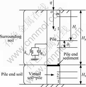
Fig. 1 Geometric model of soil-pile system
3 Governing equations and general solution
3.1 Static equilibrium equation of pile
For a single pile subjected to static vertical load at the pile head, the static equilibrium equation for the j-th pile segment can be expressed as
 (j=1, 2,��, m) (1)
where uj(z, t) is the vertical displacement of the j-th pile (including virtual soil-pile) segment. ks,j and ��s,j denote spring constant and viscosity coefficient of distributed Voigt model, respectively.
The boundary conditions of pile head and virtual soil-pile toe can be given as
 (2)
(2)
 (3)
(3)
where q is static vertical load acting on the pile head.
The boundary conditions at the interface of the pile or virtual soil-pile segments can be expressed as

 (4)
(4)
The initial conditions of the pile and virtual soil-pile segments can be expressed as
 (5)
(5)
3.2 General solution of equations
Combined with the initial conditions Eq. (5), taking the Laplace transform (two-side) of Eq. (1) yields
 (6)
(6)
where  is the Laplace
transform of uj(z, t) with respect to time; s is a complex parameter. Associating with Eq. (6), set a dimensionless eigenvalue as
 (7)
(7)
Then, the general solution of Eq. (6) can be founded as
 (8)
(8)
where Aj and Bj are complex constants which can be solved from boundary conditions.
Integrating boundary condition Eq. (3), the displacement impedance function at the head of the first virtual soil-pile segment (z=h1) can be obtained as

 (9)
(9)
where ��1=arctan[(Z0(s))/(Ep1��1)], and Z0(s) is the displacement impedance function at the bottom of the virtual soil-pile, which can be obtained from boundary condition Eq. (3).
According to the continuity conditions at the interface of pile (including virtual soil-pile) segments, it can be obtained that the displacement impedance of a pile segment is equal to that of its adjacent pile segment. Then, by means of impedance function transfer method, the displacement impedance function of the head of the j-th pile segment or virtual soil-pile segment can be derived as

 (10)
(10)
where  .
.
Through further recursion, the displacement impedance function at the pile head can be obtained as

 (11)
(11)
where  .
.
Then, the displacement transfer function at the pile head can be expressed in the following form:
 (12)
(12)
Setting s=i�� and substituting it into Eq. (12) yields the frequency response function of displacement at the pile head:
 (13)
(13)
By virtue of the inverse Fourier transform, the displacement response in the time domain at the pile head which undergoes unit load can be derived as
 (14)
(14)
Due to convolution theorem, the settlement for single pile when there is load q acting on the pile head can be derived as
 (15)
(15)
where Q(��) is the Fourier transform of q with respect to time.
During the static pile load test, the load acting on the pile head can be reduced to Eq. (16) which can be portrayed by Fig. 2:
 (16)
(16)
According to the properties of Fourier transform, the Fourier transform of f(t) in the frequency domain can be derived as

 (17)
(17)
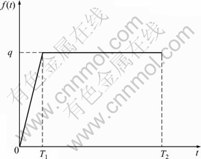
Fig. 2 Loading regime sketch
4 Parametric study and discussion
A comprehensive parametric study is conducted to show the time effect of settlement for single pile based on the solution in Eqs. (15) and (17). To highlight the influence of properties of pile end soil on the settlement behavior, the soil-pile system is divided into two layers. The first layer is soil-virtual soil-pile system and the second layer is soil-pile system. For the analysis of settlement behavior in layered soil, it is only required that the parameters of soil-pile system are due to the actual pile and soil parameters. In the follow-up analysis, the spring constant of Voigt model can be calculated by the follow equation which is derived by LIANG and HUSEIN [19]:
 (18)
(18)
where hj, Gs,j and ��j denote the length, shear modulus and Poisson ratio of the j-th soil layer. The reference value of viscosity coefficient of Voigt model is ��s,j=3.2��109 N��s/m3.
4.1 Influence of concrete strength grade on settlement behavior for single pile
During the design of pile foundation engineering, it is required to choose a reasonable concrete strength grade of pile shaft to satisfy the requirements of safety, rationality and economics. So it is very important to analyze the influence of concrete strength grade on the settlement behavior. Parameters used herein are given as follows: mass density, Poisson ratio and shear modulus of surrounding soil are 1 800 kg/m3, 0.45 and 8 MPa, respectively; thickness, mass density, elastic modulus and shear modulus of pile end soil are 1 m, 1 940 kg/m3, 24 MPa and 8 MPa, respectively; length and radius of pile are Hp=20 m and rp=0.5 m, respectively. According to Code for Design of Concrete Structures [20], the elastic modulus and concrete strength grade can be seen in Table 1.
Table 1 Elastic modulus and concrete strength grade
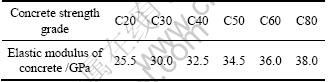
Figure 3 shows the influence of concrete strength grade on the settlement behavior for single pile. It can be noted that the settlement occurs rapidly as load acts on the pile head and the settlement increases quickly as time increases. However, the settlement gradually tends to be stable if the time is long enough. It can also be seen that the stable value of settlement decreases as the elastic modulus or concrete strength grade increases but the increase rate gradually tends to be convergent. Repeated trial calculations show that the increase of concrete strength grade has little influence on the stable value of settlement for single pile if the concrete strength grade is large enough such as C80. This means that the increase of the concrete strength grade within a certain range can reduce the settlement for single pile for the same other design parameters of the pile, but as the concrete strength grade exceeds gradually a certain value, the increase of concrete strength grade cannot affect the settlement behavior although it can improve the bearing capacity of the pile. Furthermore, Fig. 3 also shows that the stable time of settlement is not affected by the increase of the concrete strength grade.

Fig. 3 Influence of concrete strength grade on settlement behavior for single pile
It can be noted that the stable value and stable time of settlement for single pile are two important indicators in the design of pile foundation engineering. Therefore, the follow-up analysis will mainly focus on the influence of the parameters of pile end soil on these two indictors.
4.2 Influence of thickness of pile end soil on settlement behavior for single pile
Parameters used herein are set as follows: elastic modulus and radius of pile are 30 GPa and rp=0.3 and 0.5 m, respectively; thickness of pile end soil is Hb=0, 0.25, 0.5, 0.75, 1, 1.5, 2, 2.5, 3, 3.5, 4, 4.5 and 5 m, respectively; the other parameters of soil-pile system are the same as those in Section 4.1.
Figures 4 and 5 show the influence of thickness of pile end soil on the stable value and the stable time of settlement, respectively. As shown in Fig. 4, it can be noted that the stable value of settlement increases explosively as the thickness of pile end soil increases and it tends to be constant if the thickness is large enough. It can also be seen that the stable value of settlement decreases as the radius of pile increases for the same thickness of pile end soil. Figure 5 shows that the stable time of settlement increases as the thickness of pile end soil increases. When the thickness is beyond such critical influence depth, further increase of the thickness of the pile end soil has little influence on the stable time of settlement. It can also be noted that the stable time of settlement decreases as the radius of pile increases for the same thickness of pile end soil. Combined with Figs. 4 and 5, it can be found that there is a limited zone of pile end soil adjoining to the pile toe that has significant influence on the settlement behavior for single pile.
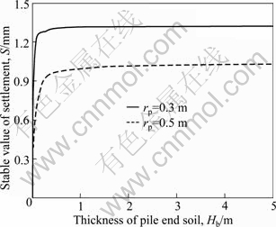
Fig. 4 Influence of thickness of pile end soil on stable value of settlement
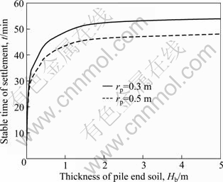
Fig. 5 Influence of thickness of pile end soil on stable time of settlement
4.3 Influence of elastic modulus of pile end soil on settlement behavior for single pile
Parameters used in this section are given as follows: thickness of pile end soil is Hb=1 m, elastic modulus of pile end soil is 10, 30, 50, 80, 100, 200, 300, 500 and 800 MPa, respectively; the other parameters of soil-pile system are the same as those shown in Section 4.2.
Figures 6 and 7 show the influence of elastic modulus of pile end soil on the stable value and stable time of settlement, respectively. As shown in Fig. 6, it can be noted that the stable value of settlement decreases as the elastic modulus of pile end soil increases. For the same elastic modulus, the stable value of settlement decreases as the radius increases. Figure 7 shows that the stable time of settlement increases as the elastic modulus of pile end soil increases and the stable time of settlement decreases as the radius increases for the same elastic modulus.
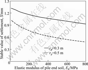
Fig. 6 Influence of elastic modulus of pile end soil on stable value of settlement
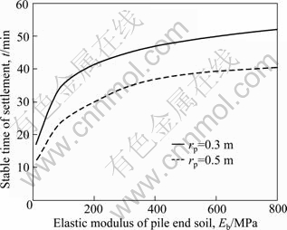
Fig. 7 Influence of elastic modulus of pile end soil on stable time of settlement
5 Application in engineering
As mentioned previously, the new approach employed in this work is based on virtual soil-pile model which can take the effect of pile end soil into account. To evaluate the reliability of this approach, Figures 8 and 9 show the comparison between the calculated and measured load-settlement curves at the head of piles T1 and T2. These examples are connected with a caisson pile installed at a site on one of the heat-engine plants in the north of Zhejiang Province, China. The length of pile T1 was 15 m and the diameter was 400 mm. The length of pile T2 was 18 m and the diameter was 600 mm. The concrete strength grade of these two piles was C60. During the pile static load test, the maximum test loads acting on the head of pile T1 and pile T2 were 1 600 kN and 5 000 kN, respectively, which had been divided into fifteen grades and twenty-five grades, respectively. For the pile T1, the test load of the first grade was 200 kN and the increment for each next grade was 100 kN. For the pile T2, the test load of the first grade was 400 kN and the increment for each next grade was 200 kN. Soil investigation revealed the following soil profile at this site: 1) When backfill to a depth of 2.5 m below the ground surface, its shear velocity and density are 100 m/s and 1 800 kg/m3, respectively; 2) At silty soil from a depth of 2.5 to 10.4 m, its shear velocity and density are 105 m/s and 1 900 kg/m3, respectively. 3) At inorganic silt from depth of 10.4-28 m, its shear velocity and density are 120 m/s and 2 000 kg/m3, respectively.
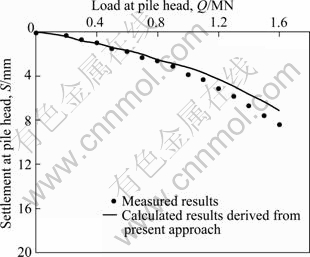
Fig. 8 Comparison between calculated and measured load-settlement behavior for pile T1 in multilayered soils
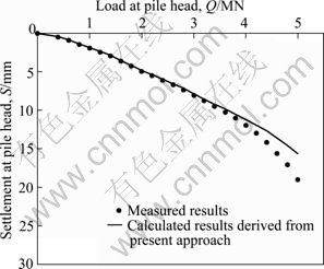
Fig. 9 Comparison between calculated and measured load-settlement behavior for pile T2 in multilayered soils
As can be seen in Fig. 8, the comparison between the calculated results and the measured results for pile T1 is rather satisfactory for the low load less than 900 kN, except at high load more than 900 kN where the calculated results are slightly less than measured results. As shown in Fig. 9, the comparison between the calculated results and the measured results for pile T2 is rather satisfactory for the low load less than 3 000 kN, except at high load more than 3 000 kN where the calculated results are slightly less than measured results. This is owing to the fact that the soil-pile system occurs plastic deformation when the load is large enough, i.e., higher than 900 kN and 3 000 kN for pile T1 and T2, respectively. The difference between the calculated results and measured results is the plastic deformation or creep deformation. Nonetheless, it can be noted that the present solution allows a good prediction of the settlement of single pile when the soil-pile system is in the elastic state. Therefore, the presented solution can be used to calculate the settlement of single pile when the load acting on the pile head is low, particularly to analyze the settlement behavior for the preliminary design of single pile.
6 Conclusions
1) By using distributed Voigt model to consider the viscoelasticity of surrounding soil layers of pile shaft, and by means of virtual soil-pile model to take the effect of pile end soil into account, a new approach is presented for the analysis of settlement behavior for single pile embedded into layered soils. The analytical solutions of displacement impedance function and settlement at the head of single pile are derived.
2) The results of parametric study show that the parameters of soil-pile system have significant influence on the settlement behavior for single pile.
3) The comparison of the load-settlement behavior for two well-instrumented field tests in multilayered soils shows that the approach proposed has enough accuracy if the soil-pile system is in the elastic state.
References
[1] HE Si-ming, GUO Qiang, LU Guo-sheng. Study on settlement calculation of single pile [J]. Chinese Journal of Rock Mechanics and Engineering, 2004, 23(4): 688-694. (in Chinese)
[2] ZHANG Zhong-miao. Pile foundation engineering [M]. Beijing: China Architecture and Building Press, 2007: 163-179. (in Chinese)
[3] SHI Pei-dong. Pile and pile foundation handbook [M]. Beijing: China Communications Press, 2008: 128-150. (in Chinese)
[4] POULOS H G. Piled raft foundations: Design and applications [J]. Geotechnique, 2001, 51(2): 95-113.
[5] ROBERTO C, ENRICO C. Settlement analysis of pile groups in layered soils [J]. Canadian Geotechnical Journal, 2006, 43(8): 788-801.
[6] ZHENG J J, ABUSHARAR S W, WANG X Z. Three-dimensional nonlinear finite element modeling of composite foundation formed by CFG�Clime piles [J]. Computers and Geotechnics, 2008, 35(4): 637-643.
[7] ZHAO M H, ZHOU G H. Bearing capacity and mechanical behavior of CFG pile composite foundation [J]. Journal of Central South University of Technology, 2008, 15(S2): 45-49.
[8] NEJAD F P, JAKSA M B, KAKHI M, MCCABE B A. Prediction of pile settlement using artificial neural networks based on standard penetration test data [J]. Computers and Geotechnics, 2009, 36(7): 1125-1133.
[9] ZHANG Q Q, ZHANG Z M, HE J Y. A simplified approach for settlement analysis of single pile and pile groups considering interaction between identical piles in multilayered soils [J]. Computers and Geotechnics, 2010, 37(7): 969-976.
[10] WEN Shi-qing, LIU Han-long, GAO Yu-feng, FEI Kang. Research on simplified calculation of settlement of cast-in-situ concrete thin-wall pipe pile composite foundation [J]. Rock and Soil Mechanics, 2004, 25(10): 1651-1654. (in Chinese)
[11] ZHANG Ding-wen, LIU Song-yu. Practical method for settlement calculation of flexible columns composite foundation under embankment [J]. Rock and Soil Mechanics, 2007, 28(6): 1133-1138. (in Chinese)
[12] ZHAO Ming-hua, ZHANG Ling, YANG Ming-hui. Settlement calculation of the long-short-pile composite foundation with shear displacement method [J]. Chinese Journal of Geotechnical Engineering, 2005, 27(9): 994-998. (in Chinese)
[13] SUN Lin-na, GONG Xiao-nan. Research on settlement calculation method of composite foundation of discrete material piles [J]. Rock and Soil Mechanics, 2008, 29(3): 846-848. (in Chinese)
[14] Ministry of Housing and Urban-Rural Development of China. JGJ94��2008. Technical code for building pile foundations [S]. Beijing: China Architecture & Building Press, 2008.
[15] ZHANG Xue-song, TU Yu-min, GONG Xiao-nan, PAN Ju-zhong. Time-dependency analysis of soil compaction pile in soft clay ground [J]. Chinese Journal of Rock Mechanics and Engineering, 2004, 23(19): 3365-3369. (in Chinese)
[16] ZENG Qing-you, ZHOU Jian, QU Jun-tong. Method for long-term settlement prediction of pile-foundation in consideration of time effect of stress-strain relationship [J]. Rock and Soil Mechanics, 2005, 26(8): 1283-1287. (in Chinese)
[17] HUANG Yu, YE Wei-ming, TANG Yi-qun, ZHAO Lin-lin. Analysis of time effect on load-settlement behavior of driven piles [J]. Chinese Journal of Rock Mechanics and Engineering, 2006, 25(8): 1710-1713. (in Chinese)
[18] CHENG Ze-hai, CHEN Yun-min, XIA Jian-zhong. Time effect of settlement for single under vertical sustained loading [J]. Rock and Soil Mechanics, 2006, 27(9): 1571-1574. (in Chinese)
[19] LIANG R Y, HUSEIN A I. Simplified dynamic method for pile driving control [J]. Journal of Geotechnical Engineering Division, ASCE, 1993, 119(4): 694-713.
[20] Ministry of Housing and Urban-Rural Development of China. GB50010��2002. Code for design of concrete structures [S]. Beijing: China Architecture & Building Press, 2002.
(Edited by YANG Bing)
Foundation item: Project(50879077) supported by the National Natural Science Foundation of China
Received date: 2011-08-30; Accepted date: 2012-02-20
Corresponding author: WANG Kui-hua, PhD; Tel: +86-571-88208708; E-mail: zdwkh0618@zju.edu.cn

