J. Cent. South Univ. Technol. (2008) 15: 198-203
DOI: 10.1007/s11771-008-0038-3

Simulation of thermal and sodium expansion stress in aluminum reduction cells
LI Jie(�� ��), WU Yu-yun(������), LAI Yan-qing(������), LIU Wei(�� ΰ),
WANG Zhi-gang(��־��), LIU Jie(�� ��), LIU Ye-xiang(��ҵ��)
(School of Metallurgical Science and Engineering, Central South University, Changsha 410083, China)
Abstract: Two finite element(FE) models were built up for analysis of stress field in the lining of aluminum electrolysis cells. Distribution of sodium concentration in cathode carbon blocks was calculated by one FE model of a cathode block. Thermal stress field was calculated by the other slice model of the cell at the end of the heating-up. Then stresses[A1] coupling thermal and sodium expansion were considered after 30 d start-up. The results indicate that sodium penetrates to the bottom of the cathode block after 30 d start-up. The semi-graphitic carbon block has the largest stress at the thermal stage. After 30 d start-up the anthracitic carbon has the greatest sodium expansion stress and the graphitized carbon has the lowest sodium expansion stress. Sodium penetration can cause larger deformation and stress in the cathode carbon block than thermal expansion.
Key words: aluminum reduction cell; stress; sodium penetration; sodium expansion; simulation
1 Introduction
The cathode carbon blocks, which act as the electrical conductor and the lining material, should have great conductivity and high corrosion resistance to the elevated molten salt. The cell��s lifespan is usually dependent on cathode blocks. The average life of large prebaked cells is short in China and from 1 300 d to 1 500 d or even less than 1 000 d[1]. In western developed countries, the average life can reach 2 500 d and the longest record is 4 000 d[2-3].
The main reason for the early failure of the cell is that the stress in the lining materials exceeds the ultimate strength of the cathode carbon blocks. The stresses are usually generated by physical and chemical effects[4]. Generally, the physical effect includes the thermal stress and the thermal shock, the chemical effect includes the chemical reaction among the aluminum, sodium and carbon, which causes the cathode carbon block��s expansion and crack. Most of all, sodium expansion is the main reason of the cathode carbon failure.
During the aluminum electrolysis, the phenomena that the expansion and rupture in the cathode carbon blocks are caused by sodium and electrolyte penetration are called the Rapoport effect[5-6].
A wide study of the sodium expansion in different graphite grade cathode carbons, from 100% amorphous to fully graphitized has been performed[7]. DEWING[8] proposed an empirical formula for expansion under
pressure. SCHREINER and ?YE[9] conducted an experimental research on a series of commercial cathode carbon blocks, and determined the sodium expansion in different carbon materials under compression. As expected, the sodium concentration was the highest in the amorphous carbon that had the largest expansion. Their experimental data were used in the present calculation. A linear relationship between sodium expansion stress and sodium concentration of the anthracitic carbon was investigated and found by ZOLOCHEVSKY et al[10-11].
Pure graphitized carbon block does not absorb sodium[12], but if it contains impurities, the sodium absorption takes place. At 1 227 K sodium will penetrate into the graphitized carbon because of its high vapor pressure.
Because the mathematical models have some advantages against on-line measurements, they have been used widely to study the physical fields of the aluminum electrolysis process[13-15]. In this work, two mathematical models of sodium penetration and sodium expansion were built up to research the sodium concentration and the sodium expansion stress in aluminum reduction cells.
2 Mathematical modeling
2.1 Material properties
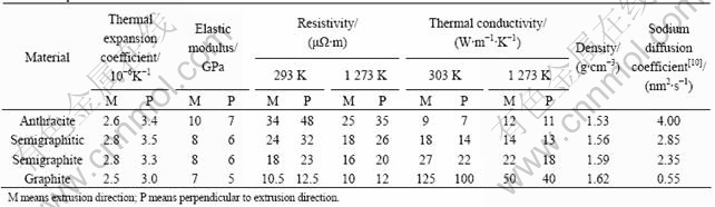
The material properties of four types of cathode carbon blocks are shown in Table 1.
Table 1 Properties of carbon used in aluminum reduction cells
2.2 Calculation of thermal field
The 3D transient thermal field can be described by the following equation[16]:
 (1)
(1)
where T is the temperature, K; �� is the density, kg/m3; c is the heat capacity, W/(kg��K); q is the heat source, J/(m3��s); t is the time, s; kx, ky and kz are the thermal conductivities in x, y and z directions, W/(m��K).
2.3 Calculation of sodium concentration distribution
The 3D concentration distribution of sodium with time can be described by the following equation[17]:
 (2)
(2)
where C is the concentration, kg/m3; t is time, s; Q is the volume source, kg/(m3��s); Dx, Dy and Dz are the diffusion coefficients in x, y and z directions, m2/s. The amount of sodium metal in a saturated amorphous carbon block is estimated to be 5.0%(mass fraction)[17].
2.4 Calculation of stress and strain
In general, a relation between stress and strain in presence of external forces acting solely on the surface of elastic anisotropic body is described by generalized Hooke��s law. Including thermal expansion and sodium expansion, the 3D equations for orthotropic material are expanded as follows[18]:
 (3)
(3)
where ��x, ��y and ��z are stresses in x, y and z directions, Pa; ��x, ��y and ��z are strains in x, y and z directions; Ex, Ey and Ez are modules of elasticity, Pa; �� is Poisson ratio; ��x, ��y and ��z are thermal expansion coefficients; ��x, ��y and ��z are sodium expansion coefficients; ��T is temperature change, K; ��C is sodium concentration change, kg/m3.
2.5 Finite element model
In order to obtain the sodium concentration distribution with time in the cathode, a single cathode carbon block model was built up by ANSYS (Fig.1). The model includes the carbon block, frozen ledge, ramming paste and cathode bars.
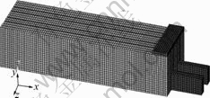
Fig.1 Finite element model of cathode carbon block
The slice model of the aluminum smelter including all kinds of materials in the cell is shown in Fig.2. The cathode is regarded as a kind of functionally graded material and has been cut into 15 layers. During calculation the sodium concentration in every layer is obtained from the result in Fig.1.
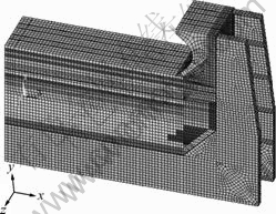
Fig.2 Slice model of aluminum reduction cell
2.6 Boundary condition
1) Convection and radiation boundary conditions are used on the outer surface of the shell.
2) Zero electric potential is applied on the surface of cathode carbon block and current is applied on the end of the cathode bar.
3) Displacement in x, y, z directions at the cell��s bottom is defined as zero.
4) The two side areas and the center area of the slice model are regard as symmetry areas.
3 Solution and discussion
3.1 Sodium penetration
Fig.3(a) shows sodium concentration distribution in anthracitic carbon after 10 d start-up, sodium has penetrated through half of the cathode carbon block. Fig.3(b) shows that sodium has penetrated to the bottom of the cathode carbon block after 30 d start-up.
Fig.3 Distribution of sodium concentration in cathode carbon block: (a) After 10 d start-up; (b) After 30 d star-tup
Fig.4 shows the variation of the sodium concentration on the surface of a carbon block with time after start-up. The sodium concentration in the carbon
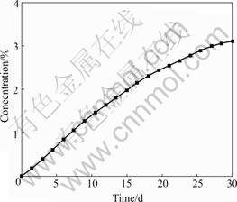
Fig.4 Variation of sodium concentration (mass fraction) with time in cathode carbon block
increases until the carbon block is saturated after infinite.
3.2 Displacement
Thermal gradient in the lining of the aluminum reduction cell is formed after start-up. Fig.5 shows the displacement of the cell. The maximum displacement in x-direction is 8.842 mm, which is located on the top side of the cell (see Fig.5(a)) and makes the cell expand toward outside. From Fig.5(b) it is seen that the y-direction displacement at the top of carbon is larger than that on the bottom, the maximum y-direction displacement is 4.192 mm, which is located at the top surface of the carbon block. y-displacement causes the cathode carbon blocks to bend upward.
Fig.6 shows the displacement of cell after 30 d start-up. The maximum displacement in the x-direction
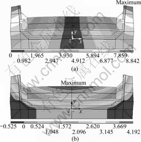
Fig.5 Displacement in aluminum reduction cell after heat-up (unit: mm): (a) x-direction; (b) y-direction
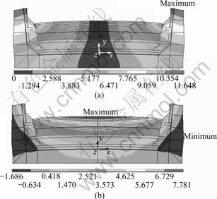
Fig.6 Displacement in aluminum reduction cell after 30 d start- up (unit: mm): (a) x-direction; (b) y-direction
and y-direction are 11.648 and 7.781 mm respectively. The x-direction and y-direction displacement increases by 31.6% and 81.7% respectively due to the thermal expansion and sodium expansion. The sodium penetration causes a change in the expansion of the cathode carbon blocks. The increased range in y-direction is more obvious than that in x-direction. The deformation of bending upward in carbon blocks becomes more seriously, which will cause the carbon surface to crack. Furthermore, sodium and the cryolite will continually penetrate into the carbon through these cracks.
3.3 Thermal stress
Taking the anthracitic carbon blocks as an example, the x-direction, y-direction, z-direction stress and equivalent stress fields without sodium expansion effect are shown in Fig.7. ���C�� means compression, and ��+��
means tension. Large stresses are concentrated in the corner of the steel bar slot at the end of the cathode carbon block. The maximum compressed stress in x-direction is -27.20 MPa. In y-direction, the largest stress is tensile stress and the value is 29.00 MPa. The maximum compressed stress in the z-direction is -46.90 MPa. The maximum equivalent stress is 50.10 MPa, which is located at the slot of the carbon block.
3.4 Coupled stress field of thermal stress and sodium expansion stress
It is seen from Fig.8 that x-direction, y-direction, z-direction and equivalent stress fields become larger after 30 d start-up due to the sodium expansion. The x-direction stress range is from -211.00 to 18.50 MPa. The compressed stress on the surface is -73.30 MPa. The maximum compressed stress in y-direction is -123.00 MPa, which is located at the corner of the steel bar slot at
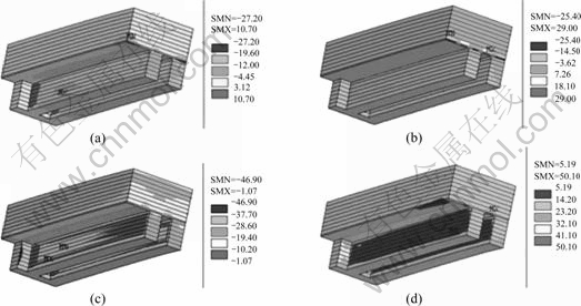
Fig.7 Stress distribution in anthracitic carbon blocks (unit: MPa): (a) x-direction; (b) y-direction; (c) z-direction; (d) Equivalent stress

Fig.8 Stress distribution in anthracitic carbon blocks after 30 d start-up (unit: MPa): (a) x-direction; (b) y-direction; (c) z-direction; (d) Equivalent stress
the end of the block. The maximum z-direction compressed stress is -130.00 MPa, which is located on the surface of the cathode carbon block. The maximum equivalent stress is 146.00 MPa. There is an equivalent stress concentration on the surface of the cathode carbon block, the value is 117.00 MPa.
3.5 Comparison of displacement and stress of different cathode blocks
Fig.9 shows the cell��s displacement of different carbon blocks. It is seen from Fig.9(a) that the cell with semigraphitic cathode carbon blocks has the largest thermal expansion displacement. The graphite carbon blocks have the smallest thermal expansion. Fig.9(b) shows the cell��s displacement with thermal and sodium expansion. Sodium can penetrate into the anthracitic carbon easily. It can be drawn from Fig.9(b) that, after 30 d start-up, the cell with anthracitic carbon blocks has the largest displacement. With the increase of graphite

Fig.9 Displacement of cell with different carbon blocks: (a) Without sodium expansion; (b) With sodium expansion
content in the carbon, the sodium concentration and sodium expansion in the carbon blocks decreases. The graphitized cathode carbon block has the lowest displacement.
Fig.10 shows the stresses in the cells with different carbon blocks. The stress in the cell with the semigraphitic carbon is the largest and that in the cell with the graphitized carbon is the lowest (Fig.10(a)). Fig.10(b) shows the thermal stress and sodium expansion stress in anthracitic carbon after 30 d start-up are the largest. As expected, the sodium expansion decreases when the graphite content increases, and the sodium expansion is small for graphitized material.
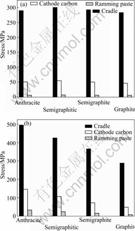
Fig.10 Stresses of cell used by different carbon blocks: (a) Without sodium expansion; (b) With sodium expansion
4 Conclusions
1) A 3D mathematical model of sodium penetration in cathode carbon block is built up, by which the sodium concentration varying with time in the carbon is calculated. The sodium concentrations in the cathode carbon block will reach a constant value.
2) A sodium expansion model of the aluminum reduction cell is built up. The thermal stress field after heat-up and the sodium expansion stress field after 30 d start-up are calculated. The results indicate that the sodium penetrates to the bottom of the cathode block after 30 d start-up. The semigraphitic carbon block has the largest stress at the thermal stage. After 30 d start-up the anthracitic carbon has the greatest sodium expansion and the graphitized carbon has the smallest sodium expansion. The cell with graphitized carbon blocks has the lowest sodium absorption and the probability of the cathode failure is smallest.
References
[1] WANG Shi-xue. Discussing of the reason for the failure of the large prebaked aluminum reduction cell and how to prolong the cell��s life[J]. Qinghai Science and Technology, 2003(4): 41-44. (in Chinese)
[2] ?YE H A, WELCH B J. Cathode performance: The influence of design, operations and operating conditions[J]. JOM, 1998, 50(2): 18-23.
[3] FENG Nai-xiang, TAN Ya-ju, DUAN Xue-liang, WU Jian-guo. Test and research of the sodium penetration and sodium expansion for the cathode carbon block in aluminum reduction cell[J]. Light Metal, 1997(6): 37-41. (in Chinese)
[4] ?YE H A, THONSTAD J, DAHLQVIST K, HANDA S, de NORA V. Reduction of sodium induced stresses in Hall-Herout cells[J]. Aluminium, 1996, 72: 918-924.
[5] GRJOTHEIMETAL K. Aluminum electrolysis fundamentals of the Hall-Herout process[M]. 2nd ed. Dusseldorf: Aluminium Verlag, 1982.
[6] S?RLIE M, ?YE H A. Cathodes in aluminum electrolysis[M]. Dusseldorf: Aluminium-Verlag, 1994.
[7] PRYNEAU J M, GASPARD J R, DUMAS D, SAMANOS B. Laboratory testing of the expansion under pressure due to sodium intercalation in carbon cathode materials for aluminum smelters[C]// CUTSHALL E R. Light Metals. Warrendale: TMS, 1992: 801-808.
[8] DEWING E W. Longitudinal stress in carbon lining blocks due to sodium expansion[C]// CAMPBELL P G. Light Metals. Warrendale: TMS, 1974: 879-887.
[9] SCHREINER H, ?YE H A. Sodium expansion of cathode materials under pressure[C]// EVANS J. Light Metals. Warrendale: TMS, 1995: 463-470.
[10] ZOLOCHEVSKY A, HOP J G, SERVANT G, FOOSNAES T, ?YE H A. Rapoport-Samoilenko test for cathode carbon materials (I): Experimental results and constitutive modeling[J]. Carbon, 2003, 41: 497-505.
[11] ZOLOCHEVSKY A, HOP J G, FOOSNAES T, ?YE H A. Rapoport-Samoilenko test for cathode carbon materials (II): Swelling with external pressure and effect of creep[J]. Carbon, 2005, 43: 1222-1230.
[12] MIKHALEV Y, ?YE H A. Absorption of metallic sodium in carbon cathode materials[J]. Carbon, 1996, 34(1): 37-41.
[13] SAYED H S, MEGAHED M M, DAWI F M, ABDAUA S H. Identification of the nonlinear swelling pressure distribution of the aluminum reduction cell[C]// DAS S K. Light Metals. Warrendale: TMS, 1997: 303-308.
[14] LIU Hai-shi, LI Jie, LI Cui-mei, ZHANG Qin-song, LIU Wei. Influence of different kinds of cathode carbon blocks on cathode thermal-field distribution in preheating process[J]. Journal of Central South University: Science and Technology, 2006, 37(1): 36-40. (in Chinese)
[15] LI Jie, DENG Xing-qiu, LAI Yan-qing, LIU Feng-qin, LIU Ye-xiang. 3D thermo-electric of 160 kA prebaked aluminum reduction cell at low cryolitic ratio and temperature[J]. Journal of Central South University: Science and Technology, 2004, 35(6): 875-879. (in Chinese)
[16] TAO Wen-quan. Theory of numerical heat transfer[M]. Xi��an: Xi��an Jiaotong University Press, 1988. (in Chinese)
[17] S?RLIE M, HVISTENDAHL J, ?YE H A. Early failure mechanisms in aluminum cell cathodes [C]// SOBODH K D. Light Metals. Warrendale: TMS, 1993: 299-308.
[18] SUN Y, FORSLUND K G, S?LIE M, ?YE H A. 3-D modeling of thermal and sodium expansion in Soderberg aluminium reduction cells[C]// ALTON T T. Light Metals. Charlotte, North Carolina: TMS, 2004: 587-592.
(Edited by YANG Hua)
Foundation item: Project(50374081) supported by the National Natural Science Foundation of China
Received date: 2007-10-25; Accepted date: 2007-12-29
Corresponding author: LI Jie, Professor; Tel: +86-731-8830474; E-mail: xbli@mail.csu.edu.cn
[A1]

