A three-dimensional matching localization algorithm based on helix triangular pyramid array
��Դ�ڿ������ϴ�ѧѧ��(Ӣ�İ�)2021���3��
�������ߣ���Ԫѩ �Ծñ� ������ ��Ծ
����ҳ�룺816 - 833
Key words��geologic hazards; infrasound; helix triangular pyramid array; 3D matchinglocalization algorithm
Abstract: On the eve of the occurrence of geological hazards, part of the rock and soil body begins to burst, rub, and fracture, generating infrasound signals propagating outward. 3D advanced positioning of the landslide has remained unsolved, which is important for disaster prevention. Through the Fourier transform and Hankel transform of the wave equation in cylindrical coordinates, this work established a three-dimensional axisymmetric sound field model based on normal waves, and designed a 4-element helix triangular pyramid array with vertical and horizontal sampling capabilities. Based on this, the three-dimensional matching localization algorithm of infrasound for geological hazards is proposed. Applying the algorithm to the infrasound signal localization of rock and soil layers, it was found that the helix triangular pyramid array can achieve accurate estimation of depth and distance with a smaller number of array elements than the traditional array, and may overcome the azimuth symmetry ambiguity. This study shows the application prospects of this method for predicting geohazards position several hours in advance.
Cite this article as: ZHAO Jiu-bin, LIU Yuan-xue, LIU Chang-jia, LING Yue. A three-dimensional matching localization algorithm based on helix triangular pyramid array [J]. Journal of Central South University, 2021, 28(3): 816-833. DOI: https://doi.org/10.1007/s11771-021-4647-4.

J. Cent. South Univ. (2021) 28: 816-833
DOI: https://doi.org/10.1007/s11771-021-4647-4

ZHAO Jiu-bin(�Ծñ�)1, LIU Yuan-xue(��Ԫѩ)1, LIU Chang-jia(������)2, LING Yue(��Ծ)1
1. Chongqing Key Laboratory of Geomechanics & Geoenvironmental Protection, Department of Military Installations, Army Logistics University of PLA, Chongqing 401311, China;
2. Beijing Institute of Special Electromechanical Technology, Beijing 100020, China
 Central South University Press and Springer-Verlag GmbH Germany, part of Springer Nature 2021
Abstract: On the eve of the occurrence of geological hazards, part of the rock and soil body begins to burst, rub, and fracture, generating infrasound signals propagating outward. 3D advanced positioning of the landslide has remained unsolved, which is important for disaster prevention. Through the Fourier transform and Hankel transform of the wave equation in cylindrical coordinates, this work established a three-dimensional axisymmetric sound field model based on normal waves, and designed a 4-element helix triangular pyramid array with vertical and horizontal sampling capabilities. Based on this, the three-dimensional matching localization algorithm of infrasound for geological hazards is proposed. Applying the algorithm to the infrasound signal localization of rock and soil layers, it was found that the helix triangular pyramid array can achieve accurate estimation of depth and distance with a smaller number of array elements than the traditional array, and may overcome the azimuth symmetry ambiguity. This study shows the application prospects of this method for predicting geohazards position several hours in advance.
Key words: geologic hazards; infrasound; helix triangular pyramid array; 3D matchinglocalization algorithm
Cite this article as: ZHAO Jiu-bin, LIU Yuan-xue, LIU Chang-jia, LING Yue. A three-dimensional matching localization algorithm based on helix triangular pyramid array [J]. Journal of Central South University, 2021, 28(3): 816-833. DOI: https://doi.org/10.1007/s11771-021-4647-4.
1 Introduction
The occurrence of geological disasters was accompanied by the generation of seismic waves and broadband sound waves. Researchers were more interested in seismic waves and had achieved remarkable results. MANCONI et al [1] also used a seismic wave network method to monitor and locate rock landslides in real time, but the positioning accuracy is only 5 km. YAN et al [2] used seismic sensors to form a network, monitored the seismic waves of Xinmo landslide and analyzed its characteristics, and found that the frequency of seismic waves was mainly concentrated below 5 Hz. KEAN et al [3] conducted an on-site debris flow model test to receive seismic waves and found that the amplitude of seismic waves is related to the volume of debris flow deposits. In terms of source inversion research, WANG et al [4] used far-field body wave data and finite fault method to quickly invert the source rupture process model of the Lushan earthquake on April 12, 2013, and calculated the theoretical intensity distribution in the epicenter area. SHANG et al [5] designed an inversion methods based on fitting the first-motion polarity in the Bayesian framework, which was applied to three representative events of different sizes in the Geysers geothermal field in California to verify its effectiveness. Due to the nonlinear relationship between surface deformation and fault geometric parameters, nonlinear algorithms such as traditional algorithms and intelligent algorithms were mainly used to search for the optimal solution of source fault parameters. Since there were many unknowns in seismic source inversion methods, some parameters such as rupture velocity, sub-fault source time function shape, and seismogenic fault mechanism need to be considered and set, so inappropriate preconditions often distorted the inversion results.
In recent years, researchers have gradually begun to study infrasound waves of geological disasters. LIU et al [6] used infrasonic wave sensors to receive signals from debris flow, and used time delay method to locate the disaster location, but the error was large and only two-dimensional positioning was possible. MARCHETTI et al [7] set up multiple infrasound sensors with a spacing of 2 km in debris flow-prone areas to form a network to monitor debris flow infrasound signals, thereby establishing a debris flow infrasound monitoring system. CUI et al [8] conducted a landslide laboratory test to collect infrasound signal characteristics and found that the central frequency of infrasound was 12.5 Hz during the crack propagation stage of the landslide, and the infrasound was concentrated at 0.5-6 Hz during the sliding and friction stages.
There were two aspects that can illustrate the advantages of using infrasound to identify and locate geological hazards in advance. First of all, because seismic waves were generated during the occurrence of geological disasters, seismic waves can only be monitored and cannot be used for early warning. However, infrasound waves were generated a few days or hours before the occurrence of geological disasters, which makes the use of infrasound waves for advance warning and positioning have inherent advantages. On the eve of the occurrence of geological disasters, local rock and soil bodies will yield and fail first, producing measurable infrasound waves. Researchers have confirmed this phenomenon through a large number of observations and experiments [9, 10]. The infrasound signal was mainly concentrated in 3.91 to 15.62 Hz [11-13]. From local rock and soil destruction, to interpenetration, to overall destruction, this process will last from several hours to several days. On the other hand, the energy of seismic waves from geological disasters was smaller than earthquake. Seismic waves can only propagate in rock and soil, not in the air. Therefore, the attenuation is very fast and cannot be transmitted over long distances. However, the propagation of infrasound waves is the micro- vibration of the medium, which can spread over long distances in rock, soil and air. This feature makes it possible to use infrasound waves for multi-target monitoring and early warning of geological disasters in a large area.
In the geological environment, when infrasound signal was received, the signal processing process of amplifying the signal, Gaussian denoising, high-pass filtering, and natural noise denoising was performed first, then data recognition technology was used to identify the type of disaster. If the type of disaster can be predicted based on the infrasound signal characteristics, and the spatial location of the disaster is located according to the infrasound receiving array, time can be gained for disaster prevention and transfer of people and property. The geological department implements long-term monitoring of disaster-prone areas. The infrasound signals are received by the array, and the signal data is transmitted from the network to the data center for real-time storage and calculation. The bottom layer of the data center stores massive infrasound disaster data. Because the infrasound signal characteristics of disasters such as landslides, mudslides, and earthquakes are different, the real-time monitoring data and disaster characteristic data in the database are processed by data mining algorithms (classification algorithm [14], neural network algorithm [15, 16], correlation algorithm [17, 18], etc.), which can realize the types of disaster prediction. Due to the development of artificial intelligence and big data, the real-time nature of data and the accuracy of data mining have been considerably improved, so the key issue is to predict the exact location of disasters in advance.
The sound field formed by the infrasound source propagating in the soil layer is determined by the nature of the sound source and the waveguide environment. Achieving passive localization of low-frequency sound sources in the soil requires sufficient spatial sampling of the sound field. The ability of spatial sampling depends on two factors: the number of array elements and the array��s space formation. Because passive positioning of geological hazards is generally implemented in mountainous areas where geological hazards occur frequently, many array elements cannot be set due to environmental conditions. One-dimensional azimuth estimation generally used the time delay method [19] and beam forming method [20], but this method could not estimate the depth and distance of the infrasound source location, and there were two disadvantages to azimuth estimation. First of all, due to the ambiguity of azimuth between 0�� and 360��, there was a pseudo sound source that cannot be distinguished. Secondly, the performance of azimuth positioning became worse as the angle changes, and the positioning effect in the end-fire direction was the worst. For two-dimensional positioning, linear and circular arrays [21, 22] were generally used, and the matching field algorithm was used to estimate the depth and distance. The disadvantage of this method was that it could not estimate the azimuth. To estimate the three- dimensional joint estimation of the distance, depth, and azimuth of the infrasound source, a formation design with horizontal sampling and spatial adoption is required. Traditional methods used geometric arrays such as cross vertical arrays [23] and cylindrical arrays [24, 25]. The disadvantages were the large number of required array elements and the existence of fuzzy symmetry.
This paper first established a two-dimensional sound field propagation model based on the normal wave model. This method described the sound field as a set of string-like vibration modes (the frequency of which is given by the horizontal wave number associated with mode propagation), whose mode contributions are weighted according to the depth of the sound source, and the sum of all mode contributions constitutes the whole sound field. This propagation model can sum the infinite modes to get an accurate solution of the sound field, and the characteristic function and Hankel function of each mode are separate variables-horizontal traveling waves are independent of depth, vertical standing waves are independent of distance and range. According to this property, a three- dimensional axisymmetric sound field model based on normal waves was obtained from the two- dimensional sound field model through geometric relations. In order to design an infrasound passive positioning array that meets the needs of geological disaster monitoring, this work proposed a three-dimensional matching localization algorithm of infrasound for geological hazards based on helix triangular pyramid array, whose 4 elements are uniformly changed on the helix, so that each element had horizontal sampling and vertical sampling capabilities. This method requires only 4 elements to estimate the distance, depth and orientation of the three-dimensional infrasound source. The advantage of this method compared with other traditional arrays was that it can achieve accurate estimation of the distance, depth and azimuth of the three-dimensional infrasound sound source with the fewest array elements, and overcome the azimuth symmetry blur. Therefore, this method has broad prospects for advanced positioning of geological disasters.
2 Sound field modeling of three- dimensional propagation theory based on normal waves
This paper used the normal wave theory to establish the geological sound field theory. The general process was as follows: due to the narrow band of the infrasound signal, the wave equation was first transformed to the Helmholtz equation by Fourier transform. Since the sound field only changes with depth and distance in the cylindrical coordinate system, the Kernel function was obtained using the Hankel transform of the fluctuation equation. Each kernel function is a set of vibration modes similar to strings, called the eigenfunction, and the independent variable of the eigenfunction is the horizontal wave number, called the eigenvalue. The normal-wave sound field model was obtained by adding the contributions of each mode according to the depth-weighted sound source [26].
2.1 Two-dimensional wave equation and Helmholtz equation in soil layer
Considering that infrasound waves propagated in the rock and soil layer, we assumed that the rock layer and the soil layer are horizontal layered waveguides, the rock layer was below the soil layer, and the respective interfaces were horizontal planes, and each layer was a homogeneous medium. The above situation was an axisymmetric propagation problem, in which the sound field only changed with depth and horizontal distance. A cylindrical coordinate system was used to describe the equation of motion, so that the z-axis passes down the sound source, and the r-axis is horizontal to the right parallel to the interfaces. In the two-dimensional rock-soil layer waveguide, taking ��r and ��z as tiny parallelogram planes with edges, the equation of motion at distance r and depth z is as follows [27]:
 (1)
(1)
 (2)
(2)
For isotropic elastic solids with Lame constants �� and �� and density ��, the displacement is represented by the scalar potential function {��, ��} as follows [28]:
 (3)
(3)
 (4)
(4)
where �� represents the potential function of the compression wave and �� represents the potential function of the shear wave. For the tiny parallelogram plane in the above waveguide, according to the cylindrical coordinate geometric equation and the equation of motion, the following formula can be obtained:
 (5)
(5)
 (6)
(6)
where ��=��rr+��zz, which is called volume strain and is related to the compression wave. For the above formula, when considering that the volume strain is zero, the above formula becomes as follows:
 (7)
(7)
 (8)
(8)
The above formula describes that the shear wave propagates at a speed of  From Eqs. (3) and (4) we can obtain:
 taking them into the motion equation, the propagation equation after ignoring the shear wave can be obtained as follows:
 (9)
(9)
 (10)
(10)
The above formula describes that the compression wave propagates at a speed of  In the absence of a sound source, the potential function satisfies the non-coupling homogeneous Helmholtz equation as follows:
 (11)
(11)
 (12)
(12)
where km=��/cp, ��m=��/cs are the wave numbers of the compression wave and the shear wave, respectively; In the above formula, Laplace operator is:
 (13)
(13)
Then in a homogeneous medium, the solution of the homogeneous equation of the above formula is as follows [29]:
 (14)
(14)
When there is no sound source in the medium, after azimuth �� integration of the Helmholtz equation and Hankel transformation, the total sound field can be obtained as follows:
 (15)
(15)
 (16)
(16)
Among them, J0(krr) is the Bessel function, the vertical wave number is:
 (17)
(17)
 (18)
(18)
Since the inverse Hankel transform must be calculated in the semi-infinite wave number domain, the square root when kr>k must be defined as follows:
 (19)
(19)
According to this definition, when z����, the first term in Eq. (14) is equivalent to a wave propagating vertically downward when kr��k, and equivalent to an exponentially decaying wave when kr>k. According to the radiation conditions, the homogeneous solution can be obtained as follows:
 (20)
(20)
In the case of a sound source in an elastic medium, the case of a simple point sound source was considered. Since the radius of the point source sphere is much smaller than the wavelength of the sound wave, the intensity of the sound source is defined as the volume injection amplitude generated by the sound source at frequency ��, where U(��) is the displacement of the sound source at a sphere radius a. Define the Green��s function g��(r, r0) as the response of the time-domain wave equation at r to the unit pulse signal at r0 in infinite medium, that is:
 (21)
(21)
For a single point source with intensity S�� at r0, the non-homogeneous Helmholtz equation for depth separation of cylindrical coordinates is as follows:
 (22)
(22)
Then the non-homogeneous wave equation of deep separation of the free-field Green��s function is as follows:
 (23)
(23)
In addition to the sound source depth z=zs, the free-field Green��s function should satisfy the homogeneous equation, and its solution should have the form of Eq. (20). Considering that the sound field is symmetrical with respect to the plane z=zs, therefore:
 (24)
(24)
Let �� be an infinitesimal quantity, the integral of Eq. (23) from zs-�� to zs+�� is given by:
 (25)
(25)
Then the depth-dependent free-field Green��s function is as follows:
 (26)
(26)
The Green��s function of a point source in infinite media can be obtained by inverse Hankel transform of Eq. (25), which is given by:
 (27)
(27)
This integration decomposes the point source sound field into many cone-shaped waves. These waves propagate in the horizontal direction as cylindrical waves; in the vertical direction, when kr
 (28)
(28)
where ��(kr, z) is called the kernel function, which is the superposition of the homogeneous solution of the depth-dependent Green��s function and the depth-separated wave equation:
 (29)
(29)
According to the boundary conditions of the medium interface, the value of the undetermined coefficient of the homogeneous solution is determined. Since the denominator of the homogeneous solution contains a trigonometric function, there are poles on the discrete wave number. The normal wave model uses integral lines to surround these poles, and calculates the sum of the residues of the enclosed poles to obtain the total sound field. Using the relationship between the Bessel function and the Hankel function, the integral of Eq. (29) can be transformed into the integral of the Hankel function (representing the radiation wave at infinity):
 (30)
(30)
Because of the gradual nature of the Hankel function, the integral envelope can be closed in the upper half of the space, and the integral can be replaced by the sum of the residues of the enclosed poles. Its integral becomes the sum of infinite residues in the form sin(kzmz) as follows:
 (31)
(31)
2.2 Three-dimensional normal wave model in soil layer
It can be known from the above that the normal wave model adds the feature functions of the propagation modes with real poles  (m=1, 2, ��) to obtain the entire sound field. It can be seen from Eq. (31) that the characteristic function is a normal wave function, which is composed of a set of orthogonal and normalized mode functions, with characteristics that it changes with depth and does not change with distance under the entire sound field waveguide environment; for Hankel��s function:
 (32)
(32)
It can be seen that Hankel��s function does not change with distance but with depth. Therefore, in the axisymmetric three-dimensional waveguide environment, if the normal wave function and wave number in the two-dimensional waveguide environment are obtained, the sound field related to the azimuth can be inferred. As shown in Figure 1,let point B be the sound source point, the angle between the vector Rs pointing from the origin to the sound source and the horizontal axis is fs, point A is the element of the receiving array, and the angle between the vector RR pointing from the origin and the horizontal element is fR.
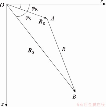
Figure 1 Diagram of sound source and receiving point
Since the sound pressure in cylindrical coordinates was related to distance and depth, the sound pressure at receiving point A is related to its distance from the sound source and its depth. Equation (31) is a two-dimensional normal wave sound field model. Under the condition of axial symmetry, we need to extend the two-dimensional normal wave sound field model to the three- dimensional normal wave sound field model. Let the position vector of the sound source be  and the position vector of the receiving element be
 then the horizontal distance between the sound source and the receiving element is as follows:
 (33)
(33)
Substituting the above formula into a two-dimensional normal wave model, the sound pressure at point A is calculated as follows:
 (34)
(34)
So far, we had obtained an axisymmetric three-dimensional sound field calculation formula. By setting different array forms in the sound field environment, due to the anisotropy of the relative position between the array elements, the signals obtained by the array elements sampling the same sound source were different, so that the array had spatial orientation resolution capabilities. It could be known from the above that the eigenfunction of the sound field and the Hankel function were separate variables, that is, the horizontal traveling wave had nothing to do with depth, and the vertical standing wave had nothing to do with distance and range. Therefore, three-dimensional positioning needs to achieve horizontal sampling and vertical array design. Therefore, this paper designed a helix triangular pyramid array with a smaller number of array elements and spatial azimuth resolution. The next section would introduce it.
2.3 3D sound field simulation of axisymmetric environment
In order to reflect the three-dimensional sound field propagation law of the soil layer, the acoustic simulation software kraken was used to simulate the three-dimensional sound field. Figure 2 shows the 1/4 waveguide model. Considering that the interfaces between soil layer, air layer, and rock layer were all flat, this model is an axisymmetric model, and set the media parameters in the model according to Ref. [30]. The soil layer is a 2000 m thick soil layer composed of clay. ��1=2000 kg/m3, cp1=1500 m/s, and the shear waves are ignored. The lower layer is composed of limestone with a thickness of 2000 m, ��2=3500 kg/m3, cp1=3200 m/s, cs1=1500 m/s. The sound source is located at 1000 m in the soil layer, and its frequency is 10 Hz. The upper interface of the soil layer is air, and the sound waves undergo soft boundary reflection. The lower layer is limestone, and the sound waves in the soil layer are emitted from the hard boundary at the interface of the bottom layer.
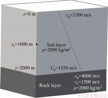
Figure 2 1/4 terrain model in the 3D sound field simulation, as well as the parameters of the soil layer and the rock layer, where the upper and lower interfaces of the soil layer and the rock layer are parallel planes
As shown in Figures 3 and 4, three- dimensional sound intensity horizontal slices at depths of 1000 and 200 m are shown, and Figure 5 is a three-dimensional sound pressure vertical slice with azimuth angle f=30��. Since the simulation here is an axisymmetric waveguide, it is the same for the vertical sound field slice of 0��-360��. For the slice in the horizontal direction, the sound pressure is attenuated as the distance increases, and the sound wave phase changes with the distance, so the arbitrary depth in the horizontal direction is different. It can be seen from Figures 3 and 4 that the sound pressure horizontal slices with a depth of 1000 m and a depth of 200 m are different. For a horizontal slice of a certain depth, the sound pressure changes with the distance from the sound source. The reason is that the sound pressure is attenuated with the distance, and the sound wave phase is changed in the waveguide. At some point, sound waves of the same phase will resonate, while sound waves of different or opposite phases will cancel each other out.
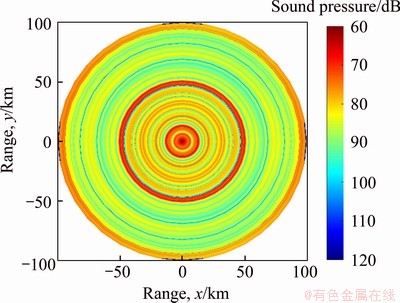
Figure 3 Horizontal sound pressure slice of zs=1000 m, zr=1000 m
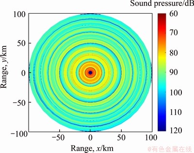
Figure 4 Horizontal sound pressure slice of zs=1000 m, zr=200 m
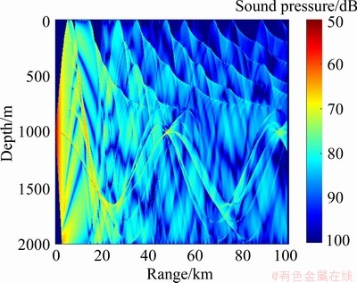
Figure 5 Vertical sound pressure slice of zs=1000 m, f=30��
3 Helix triangular pyramid array and matching positioning for 3D sound field
To make the receiving array have three-dimensional signal sampling capability, multiple linear arrays need to be arranged in the horizontal and vertical directions. Traditional receiving arrays included vertical cross arrays (horizontal and vertical layouts of receiving array elements), and cylindrical arrays (horizontal circumferences and vertical layouts of receiving array elements). However, this array element layout method required a large number of array elements, and the horizontal (vertical) direction had only a single-dimensional sampling capability. On the other hand, due to the lack of spatial sampling capabilities, there would be a large number of sidelobes on the ambiguity surface with high energy, which would not accurately locate the target. In addition, due to the limitation of the spatial layout of the vertical cross array, the sampling of the azimuth also had a symmetric blur effect. In the application of 3D geological sound field localization, it was necessary to design a geometrically optimized array design with a small number of array elements, sufficient spatial signal sampling, and no azimuthal symmetrical blur. This work proposed helix triangular pyramid array with the above characteristics, which could be applied to three-dimensional geological disaster location scenarios.
3.1 Design of helix triangular pyramid array
The helix structure was developed by biochemists COCHRAN et al in 1952 [31] when studying complex biomolecular structures, and they found that the diffraction image of the DNA structure conformed to the three-dimensional Fourier transform of the Helix function, and they further confirmed that the DNA structure was a three-dimensional double helix structure. The helix structure has mathematically concise expressions, as well as analytical three-dimensional Fourier transform expressions. Its geometric expression is as follows:
 (35)
(35)
Among them, a is the bottom radius of the helix structure, b is the linear velocity of the helix rising along the z-axis, and �� is the angle that the helix rotates along the z-axis. Rewriting Eq. (35) into a two-dimensional impact function, the analytical expression of a single helix in Cartesian coordinate system is as follows [32, 33]:
 (36)
(36)
Four receiving elements are set on a single helix, and the helix position coordinates of each element are Rn(rn, fn, zn)=Rn(r0, ��0+n����, z0+n��z), n=1, 2, 3, 4 where ���� and ��z are the interval differences between the azimuth and vertical height of each array element of a single helix. The elements of the spiral array are distributed at equal intervals in the vertical direction and at equal positions in the horizontal direction, and its envelope is a cylindrical surface. After connecting the four array elements with a straight line, the space appears as a triangular pyramid, as shown in Figure 6.
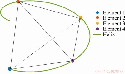
Figure 6 Schematic diagram of spiral triangle pyramid
Let the coordinates of the helix triangular pyramid array element be as follows:
 (37)
(37)
Then according to Eq. (34), the sound pressure of each element can be obtained as follows:
 (38)
(38)
The helix triangular pyramid array had the following characteristics: (1) The array elements distributed by spiral transformation were presented as a triangular pyramid array. Since each array element had the ability to sample signals in the horizontal and vertical directions, it could reduce the array elements by 50% compared to the vertical cross array. (2) Since the helix triangular pyramid array could optimize the design of horizontal and vertical apertures, and any three array elements were not on the same straight line, the array design had more flexibility and greater spatial orientation. Compared with linear arrays and oblique arrays, this array design had no symmetric ambiguity in azimuth localization. (3) Because the distance, orientation and depth of the helix triangular pyramid array were different from each other, which were the three dependent variables of the sound pressure value, this array could analyze the vector properties in the sound field. Vector research on sound field is very popular recently, and it is of great significance in future experimental research.
3.2 3D matching localization algorithm
The idea of matching localization was a generalization of beamforming. The traditional beamforming method could perform azimuth localization of one-dimensional sound source, and two-dimensional matching field could realize localization of distance and depth. Three- dimensional matching localization algorithm this work proposed could realize localization of depth, displacement and azimuth. This method was to match the actual sound field signal received by the helix triangular pyramid array in space with the copy sound field signal at the position in the simulation model where the infrasound signal may be emitted, and performed a matching operation according to a cost function. Its maximum value was the predicted sound source position. The matching process was as follows.
Firstly, in an actual waveguide environment, a helix triangular pyramid array was arranged in the soil layer or in the air to receive infrasound sensors in areas where geological disasters were frequent. Secondly, in the simulation software, a sound field calculation model was established according to the actual environment. The environmental parameters of the geological sound field, the array and position of the receiving sensors need to be same with actual situation. At the same time, the search grid space was set in the simulation software, and the sound source signals were sequentially arranged on all grids in the search space. The acoustic software was used to calculate the signal of the receiving element, which was called the copy field. The copy field and the measurement field were matched by a cost function to obtain the depth-distance fuzzy peak map of the search space and the azimuth estimated fuzzy plane map. When the position of the search grid was the same as the actual position, the cost functions of the depth-distance estimation fuzzy peak map and the azimuth estimation fuzzy plane map reached the maximum, it could be determined that the position is the sound source position [34]. The specific algorithm is shown in Figure 7.
4 Simulation analysis of matching localization
In the application scenario of infrasound source location for geological disasters, the infrasound signal was received by the infrasound receiving array, and the data center analyzed the infrasound signal to identify the type of infrasound disaster (landslide, mudslide, collapse, etc.). According to the type of infrasound disaster, the corresponding infrasound source signal was extracted from the infrasound disaster database, and the infrasound source signals were set one by one in the search space grid in the simulation environment for matching and localization. In this section, an infrasound source was set up in the soil layer of the simulation environment. The infrasound source was matching located by using a helix triangular pyramid array and a cross array. The localization effects of the two methods were compared and analyzed.
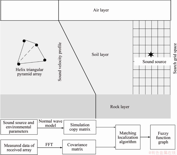
Figure 7 Matching field algorithm flow
4.1 3D matching localization of helix triangular pyramid array
The waveguide model shown in Figure 7 was used to analyze the three-dimensional matching localization of the helix triangular pyramid array. According to Ref. [30], the media parameters in the model were as follows: The upper layer was air layer with height of 150 m, ��1=1.396 kg/m3, cp1=340 m/s. The upper and lower interfaces of the air layer are horizontal planes. The middle layer is soil layer composed of clay, with a thickness of 600 m, ��2=2000 kg/m3, cp2=1500 m/s. Ignoring the shear wave, the attenuation coefficient of the soil layer is 0.15 dB/��. The bottom half is composed of limestone, ��3=3500 kg/m3, cp3=3200 m/s, cs3=1500 m/s, and the attenuation coefficient of the bottom is 0.2 dB/��. A 4-element helix triangular pyramid array is placed in the soil layer, with a horizontal aperture of 20 m and a vertical aperture of 30 m, and the deployment depth is 80-180 m. The projection point of the center point of the helix triangular pyramid array on the top plane of the air layer is the origin of the cylindrical coordinate system, the z-axis is vertically downward, the r-axis is horizontal to the right, and the azimuth is positive counterclockwise. The infrasound source is 1800 m away from the origin, 170 m deep, azimuth is 30��, and the low frequency signal is 10 Hz. Assuming that the received power of the interference source and uncorrelated noise is 20 dB, the variable coefficient likelihood method of matching localization was used for comparison and analysis.
Set the search distance interval to 1000-2000 m and the number of searches to 100 times; set the search depth to 120-320 m and the number of searches to 100 times; set the search range to 0��-360�� and the number of searches to 100 times. When the azimuth was constant and the distance and depth were changed, the depth-distance estimation fuzzy function plane slice and the depth-distance estimation fuzzy function peak maps were output, as shown in Figure 8; When the depth and distance were constant and the azimuth was changed, the azimuth estimation fuzzy function graphs were output, as shown in Figure 9. Figure 8 shows the slicing and peak plots of the depth- distance estimation fuzzy function when the azimuth fs=-5��/6, -��/6, ��/6, ��/2. From the fuzzy function plane slices could see the estimated depth-distance at various angles, and from the peak value could see the maximum cost function of depth-distance-azimuth. When fs=-5��/6, -��/6, the side-lobe effect of the fuzzy function slice graph and peak graph are large, which have affected the judgment of depth-distance estimation, so it is impossible to perform depth distance estimation. The maximum value of the peak value of the blur function is 0.6371 and 0.701, which are not the maximum values of the blur function in all directions, so it cannot be judged as the estimated sound source at this time. When fs=��/2, the sidelobe effect decreases, and the peak value of the blur function is 0.8814, which is not the maximum value of the blur function in all directions, so it cannot be judged as the sound source estimate. When fs=��/6, the sidelobe effect is the smallest, and its peak value of the blur function is 1.662, which is the maximum value of the peak value of the blur function output in all directions. Therefore, the depth and distance at this time are determined as the infrasound source estimates, Zs=180 m, Rs=1800 m.
When the depth and distance were determined, the azimuth fuzzy function estimation map was output. As shown in Figure 9, when the orientation changes from 0�� to 360��, the fuzzy function of the output is 1.662 when fs=��/6, which is consistent with the peak value of the fuzzy function of depth distance estimation. Therefore, we could determine that the predicted sound source position was Zs= 180 m, fs=��/6, Rs=1800 m. The value is the same as the real infrasound source, which showed that the matching localization algorithm based on the helix triangular pyramid array can accurately locate the three-dimensional position of the infrasound source under random noise, and had broad prospects in the application of geological disaster advanced prediction of location.
4.2 3D localization simulation of cross array
In order to compare with the spatial positioning performance of the helix triangular pyramid array, the four-, eight- and twelve-element cross arrays were used for localization in three-dimensional space, and compared and analyzed. The cross array is a combination of a vertical array and a horizontal array, and the array elements were symmetrically distributed according to the center point. The location and properties of the infrasound source and the waveguide environment of the cross-array simulation environment were the same as those of the helix triangular pyramid array. First analyzed from the depth-distance estimation, and then analyzed the azimuth estimation. The simulation results are shown in Figure 10, which respectively shows the effect of the depth-distance estimation of the cross array with different numbers of elements when the azimuth is fs=��/6. We could see from Figures 10(a) and (b) that the four-element cross-array depth- distance estimation fuzzy function peak map cannot locate its sound source position, due to the existence of multiple peaks, and the positioning effect is poor. From Figures 10(c) and (d), it can be seen that the cross-array depth-distance estimation fuzzy function positioning effect is significantly improved after the number of array elements is increased by 4 elements, and its localization positon is Zs=180 m, Rs=1800 m. Although the cross array can accurately locate, there are still two fuzzy side lobes, which affect the accuracy of localization. The following analysis of Figures 10(e) and (f) shows that the depth-distance ambiguity function of the 12-element cross array can accurately locate the depth and distance of the infrasound source, and it has almost no side lobes, which will not affect the localization judgment.
However, because the cross array was a symmetric array, there was azimuth fuzzy symmetry when performing azimuth estimation, that is, there were two estimated infrasound sources. As shown in Figure 11, the 12-element cross array azimuth estimation fuzzy function graph has two peaks at fs=��/6, 5��/6, and it is impossible to determine which is the position of the infrasound source. From the above analysis, although increasing the number of array elements could improve the performance of depth distance estimation, it could not overcome the shortcomings of fuzzy symmetry of azimuth estimation. Our conclusion was that using the helix triangular pyramid array, because its array elements had the ability to sample signals in the horizontal and vertical directions, and any three array elements were not on the same straight line, it had the advantage of overcoming the ambiguity of azimuth estimation. In addition, the helix triangular pyramid array could perform accurate depth-distance- azimuth estimation with a smaller number of array elements.
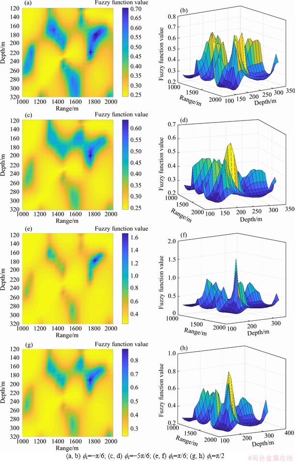
Figure 8 Fuzzy function slices and corresponding peak maps of depth-distance estimation in different orientations:
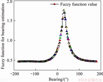
Figure 9 Fuzzy function of azimuth estimation of helix triangular pyramid array
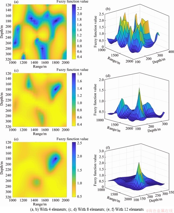
Figure 10 Depth-distance estimation fuzzy function slices and corresponding peak maps of cross arrays with different numbers of array element at fs=��/6:
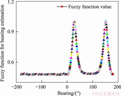
Figure 11 Fuzzy function of 12-element cross array orientation estimation.
4.3 Application of landslide positioning
The Gaozi Henan landslide was located in Zhongxian County, Chongqing, China, on the slope of the right bank of the Yangtze River. The mountain where the landslide located was an axisymmetric mountain with an elevation of 500 m. The micro-topography of the landslide area was a gentle slope and a secondary platform. The elevation of the platform was about 220 m, and the topographic slope angle of the landslide area was about 18�� on average. The slid mass was clay mixed with gravel, and the underlying bedrock was dominated by mudstone of the Penglaizhen Formation of the Upper Jurassic. The surface water bodies in the landslide area included rice fields, fish ponds, weir ponds and gullies. The types of groundwater were loose soil pore water and bedrock fissure water. The surface water and groundwater were discharged from the landslide to the Yangtze River. The surface water seeps in the rainy season, softens the soil, and reduces the shear strength of the soil, resulting in the deformation of the landslide.
According to the topography of the landslide, the axisymmetric geological model with size of 10 km��10 km��500 m was established (Figure 12), and its media parameters were consistent with those of the model in Figure 7. Assuming that the location at the rear edge of the landslide where the coordinates were (1.6 km, 220 m, 20��), local soil damage occurred first, and the infrasound signal with frequency of 10 Hz would be generated and spread outwards. This signal could be used as a precursor to predict landslide instability signal.
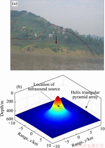
Figure 12 Real scene of landslide (a) and axisymmetric mountain model based on landslide topography (b)
With the coordinates (6 km, 300 m, 30��) as the center, the spiral triangular pyramid array was set to monitor the infrasound signal, and the method proposed in this paper was used to locate the infrasound source.
Set the search distance interval to 1000-2000 m, and search times as 100 times; set the search depth to 120-320 m, and search times as 100 times; set the search range as 0��-360��, and search times as 100 times. When the azimuth was constant and the distance and depth were changed, the depth-distance estimation fuzzy function plane slice were output; When the depth and distance were constant and the azimuth was changed, the azimuth estimation fuzzy function graphs were output. Finally, find the maximum value in the depth- distance estimation fuzzy plane slices, and its corresponding coordinate was the depth-distance estimation. Find the maximum value in the azimuth estimation ambiguity function graphs, and its corresponding azimuth was the sound source azimuth estimation. As shown in Figure 13, the maximum value of the two ambiguity functions was 2.05823. At this time, the depth, distance and azimuth of the infrasound source are estimated to be (1.6 km, 220 m, 20��), which was consistent with the actual coordinates, indicating that the method accurately located the local damage of the landslide. After accurately locating the landslide, preventive measures such as setting up retaining walls, unloading the upper load of the landslide, and draining water were taken at the initial stage of landslide deformation to avoid landslide damage.
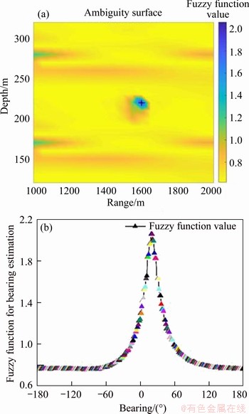
Figure 13 Maximum depth-distance estimation fuzzy plane slice (a) and maximum azimuth estimation ambiguity function graph (b)
5 Discussion
What needs to be discussed here was the innovation and application prospects of the method proposed in this work, as well as the advantages compared with traditional methods. Traditional methods used seismic waves to monitor and provide early warning of geological disasters [1], but the significance of monitoring and early warning lies in predicting the probability, time and location of the occurrence of geological disasters in advance, so as to gain time and initiative for disaster prevention and control. However, seismic waves were generated at the same time as geological disasters and could not be used for advanced prediction and advanced positioning. The innate advantage of infrasound waves over seismic waves was that infrasound waves were generated a few days or hours before the occurrence of geological disasters, so it was feasible to use infrasound waves to predict and locate disasters in advance. The method in this article had the following advantages: First of all, through the Fourier transform and Hankel transform of the wave equation, and the use of geometric spatial relations, the three-dimensional axisymmetric normal wave sound field model was established, which solved the limitation that the traditional normal wave sound field model could only solve the two-dimensional sound field. The established three-dimensional axisymmetric model could solve the sound pressure field of different depths, distances and azimuths in the sound field, which was suitable for solving the infrasound source of axisymmetric geological models. Next, the helix triangular pyramid array designed in this paper only needs 4 elements to realize the positioning of geological disasters in the geological environment, which was very suitable for geological disaster positioning application scenarios. As we all know, the more array elements, the better its positioning performance. For example, CHEN et al [35] designed a 64-element array to locate cars, but this huge number of array elements was not suitable for natural environments with harsh geological environments. The natural environment required an array with a small number of array elements and stable array performance, and these requirements were just the advantages of this design. Compared with the number of elements of the traditional cross array, circular ring array, etc., the helix triangular pyramid array only needs 50% of elements to achieve the same positioning performance, and there was no ambiguity [33]. Finally, this paper adopted the robust matching positioning algorithm that can quickly search and locate infra-sound sources, so that it can quickly locate geological disasters in advance, revealing the feasibility of this method in the field of geological disaster monitoring and early warning.
What should be noted is that the location of the array and the arrangement of the array elements are not unique. On the one hand, the array can be arranged in the soil layer, in the air, or separately in the soil layer and the air. On the other hand, under the condition that each array element satisfies the Nyquist sampling theorem-the wave length of the sound wave from a point sound source to two adjacent sampling points is less than ��min/2, the position of each element in the array can be not unique.
6 Conclusions
In this paper, a three-dimensional geological acoustic field model based on normal waves had been established, and a three-dimensional matching localization algorithm of helix triangular pyramid array for infrasound signals of geological disasters had been proposed. The conclusions had been obtained as follows:
The wave equation was Fourier transformed to Helmholtz equation, and the kernel function of the wave equation was obtained by Hankel transformation in the cylindrical coordinate system, thereby establishing the two-dimensional normal wave model based on the sum of contributions of modes weighted by depth. According to the nature of depth and distance separation of the two-dimensional normal wave model, the three-dimensional axisymmetric geological acoustic field model was established through the geometric relationship between the sound source and the receiving array. The model is suitable for column-symmetric topographic and geomorphic environments, such as geological models with horizontally superimposed strata, and axisymmetric mountain models.
Each element of the helix triangular pyramid array designed in this paper has horizontal and vertical sampling capabilities, and any three elements are not on the same straight line, so the helix triangular pyramid array has more flexibility and greater spatial orientation. Therefore, using this array for three-dimensional matching localization can achieve accurate depth and distance estimation with a smaller number of array elements than the cross array, and there is no azimuthal ambiguity in azimuth estimation.
The three-dimensional matching localization algorithm for infrasound signals of geological disasters based on the normal wave model was proposed. This algorithm searched and matched in a predetermined area in the geological model, and the maximum value of the matching fuzzy function was the predicted sound source point. This algorithm is suitable for predicting upcoming disasters and accurately locating spatial location a few hours before geological disasters including landslides, mudslides, and landslides. It provides new ideas for the prevention and control of geological disasters.
Contributors
The overarching research goals were developed by LIU Yuan-xue. ZHAO Jiu-bin provided the first draft of manuscript. LIU Chang-jia conducted data processing. LING Yue conducted the literature review. All authors replied to reviewers�� comments and revised the final version.
Conflict of interest
ZHAO Jiu-bin, LIU Yuan-xue, LIU Chang-jia, LING Yue declare that they have no conflict of interest.
References
[1] MANCONI A, PICOZZI M, COVIELLO V, DESANTIS F, ELIA L. Real-time detection, location, and characterization of rockslides using broadband regional seismic networks [J]. Geophysical Research Letters, 2016, 43(13): 6960-6967. DOI: https://doi.org/10.1002/2016GL069572.
[2] YAN Yan, CUI Yi-fei, GUO Jian, HU Sheng, WANG Zi-ang, YIN Shu-yao. Landslide reconstruction using seismic signal characteristics and numerical simulations: Case study of the 2017 ��6.24�� Xinmo landslide [J]. Engineering Geology, 2020, 270: 105582. DOI: https://doi.org/10.1016/j.enggeo.2020. 105582.
[3] KEAN J W, COE J A, COVIELLO V, SMITH J B, MCCOY S, ATRATTANO M. Estimating rates of debris flow entrainment from ground vibrations [J]. Geophysical Research Letters, 2015 42(15): 6365-6372. DOI: https://doi.org/10.1002/2015GL064811.
[4] WANG W M, HAO J L, YAO Z X. Preliminary result for rupture process of Apr. 20, 2013, Lushan Earthquake, Sichuan, China [J]. Chinese J. Geophys, 2013, 56(4): 1412-1417. DOI: 10.60358/cjg20130436. (in Chinese)
[5] SHANG Xue-yi, TKALCIC H. Point-source inversion of small and moderate earthquakes from P-wave polarities and P/S amplitude ratios within a hierarchical Bayesian framework: Implications for the geysers earthquakes [J]. Journal of Geophysical Research: Solid Earth, 2020, 125(2): 1-64. DOI: 10.1029/2019JB018492.
[6] LIU Dun-long, LENG Xiao-peng, WEI Fang-qiang, ZHANG Shao-jie, HONG Yong. Visualized localization and tracking of debris flow movement based on infrasound monitoring [J]. Landslides, 2018, 15: 879-893. DOI: https://doi.org/10. 1007/s10346-017-0898-4.
[7] MARCHETTI E, WALTER F, BARFUCCI G, GENCO R, WENNER M, RIPEPE M, MCARDELL, PRICE C. Infrasound array analysis of debris flow activity and implication for early warning [J]. Journal of Geophysical Research: Earth Surface, 2019, 124: 567-587. DOI: https://doi.org/10.1029/2018JF004785.
[8] CUI Wen-jie, TENG Peng-xiao, HAN Bao-kun. Characteristics of infrasound signals just before landslide [J]. Technical Acoustics, 2018, 37(2): 157-162. DOI: https:// doi.org/10.16300/j.cnki.1000-3630.2018.02.011. (in Chinese)
[9] LIN Qi-bin, CAO Ping, LI Kai-hui, CAO Ri-hong, ZHOU Ke-ping, DENG Hong-wei. Experimental study on acoustic emission characteristics of jointed rock mass by double disc cutter [J]. Journal of Central South University, 2018, 25(2): 357�C367. DOI: https://doi.org/10.1007/s11771-018-3742-7.
[10] CHEN Xu, TANG Chun-an, YU Jin, ZHOU Jian-feng, CAI Yan-yan. Experimental investigation on deformation characteristics and permeability evolution of rock under confining pressure unloading conditions [J]. Journal of Central South University, 2018, 25(8): 1987-2001. DOI: https://doi.org/10.1007/s11771-018-3889-2.
[11] JIA Bing, WEI Jian-ping, WEN Zhi-hui, WANG Yun-gang, JIA Lin-xing. Study on prediction of coal sample damage by infrasound [J]. Progress in Geophysics, 2017(4): 357-362. DOI: https://doi.org/ 10.6038/pg20170448. (in Chinese)
[12] XU Hong, ZHOU Ting-qiang. Energy characteristics of infrasound abnormality during rock deformation and failure of rock [J]. Chinese Journal of Geotechnical Engineering, 2016, 38(6): 1044-1050. DOI: https://doi.org/10.11779/ CJGE201606010. (in Chinese)
[13] ZHU Xing, XU Qiang, TANG Ming-gao, FU Xiao-min, ZHOU Jian-bin. Experimental study of infrasound wave generated by typical rock fracture [J]. Rock and Soil Mechanics, 2013, 34(5): 1306-1312. DOI: https://doi.org/ 10.16285/j.rsm.2013.05.012. (in Chinese)
[14] WAN Xiao-xue, CHEN Xiao-fang, GUI Wei-hua, YUE Wei-chao, XIE Yong-fang. A novel shapelet transformation method for classification of multivariate time series with dynamic discriminative subsequence and application in anode current signals [J]. Journal of Central South University, 2020, 27(1): 114-131. DOI: https://doi.org/10.1007/ s11771-020-4282-5.
[15] ZHAO Jiu-bin, LIU Yuan-xue, LIU Na, HU Ming. Spatial prediction method of regional landslide based on distributed bp neural network algorithm under massive monitoring data [J]. Rock and Soil Mechanics, 2019, 40(7): 2866-2872. DOI: https://doi.org/10.16285/j.rsm.2018.0593. (in Chineses)
[16] LI Zhong-mei, GUI Wei-hua, ZHU Jian-yong. Fault detection in flotation processes based on deep learning and support vector machine [J]. Journal of Central South University, 2019, 26(9): 2504-2515. DOI: https://doi.org/ 10.1007/s11771-019-4190-8.
[17] ZHAO Jiu-bin, LIU Yuan-xue, LIU Na, HU Ming. Association rules of monitoring and early warning by using landslides FRPFP model��Case study of Jiangjin-Fengjie reach in three gorges reservoir area [J]. Chinese Journal of Geotechnical Engineering, 2018, 41(3): 492-500. DOI: https://doi.org/10.11779/CJGE201903011. (in Chinese)
[18] SAMPATH A K, GOMATHI N. Decision tree and deep learning based probabilistic model for character recognition [J]. Journal of Central South University, 2017, 24(11): 2862-2876. DOI: https://doi.org/10.1007/s11771-017- 3701-8.
[19] CELIK G, CELEBI H. Theoretical limits for time delay based location estimation in cooperative relay networks [J]. Wireless Personal Communications, 2014, 75(4): 2429-2448. DOI: https://doi.org/10.1007/s11277-013-1475-3.
[20] MA Wei, LIU Xun. Compression computational grid based on functional beamforming for acoustic source localization [J]. Applied Acoustics, 2018, 134: 75-87. DOI: https:// doi.org/10.1016/j.apacoust.2018.01.006.
[21] WORTHMANN B M, BRIAN M, DOWLING D R. High frequency source localization in a shallow ocean sound channel using frequency difference matched field processing [J]. The Journal of the Acoustical Society of America, 2015, 138(6): 3549-3562. DOI: https://doi.org/10.1121/1.4936856.
[22] LE Zuo, JIN Pan, SHEN Zhong-xiang. Analytical algorithm for 3-D localization of a single source with uniform circular array [J]. IEEE Antennas and Wireless Propagation Letters, 2018, 17(2): 323-326. DOI: https://doi.org/10.1109/LAWP. 2017.2788448.
[23] XU Zhi-yong, ZHAO Zhao. Perturbation sensitivity analysis of azimuth estimation of the acoustic source for the planar microphone array [J]. Journal of Xiadian University, 2017, 44(4): 95-99+150. DOI: https://doi.org/10.3969/ji.ssn. 1001-2400.2017.04.017. (in Chinese)
[24] NICOLAS B, JEROME I M, LACOUME J L. Source depth estimation using a horizontal array by matched-mode processing in the frequency-wavenumber domain [J]. EURASIP Journal on Advances in Signal Processing, 2006, 2006(2): 1-16. DOI: https://doi.org/10.1155/ASP/2006/ 65901.
[25] KE Wei, ZHANG Ming, ZHANG Tie-cheng. Three- dimensional sound source localization using distributed microphone arrays [J]. Chinese Journal of Acoustics, 2017(2): 89-102. DOI: https://doi.org/10.15949/j.cnki.0217-9776. 2017.02.008.
[26] PORTER M B. A numerical method for bottom interacting ocean acoustic normal modes [J]. Journal of the Acoustical Society of America, 1985, 77(5): 1760-1767. DOI: https://doi.org/10.1121/1.391925.
[27] KORSKY H. Stress waves in solids [J]. Journal of Sound and Vibration, 1964, 1(1): 88-110. DOI: https://doi.org/ 10.1016/0022-460X(64)90008-2.
[28] BREKHOVSKIKH L M, LYSANOV Y P. Fundamentals of ocean acoustics [M]. Berlin: Springer, 2003: 822-823. DOI: https://doi.org/10.1007/978-3-662-02342-6.
[29] JENSEN F B, KUPERMAN W A, PORTER M B, SCHMIDT H. Computational ocean acoustics [J]. Computers in Physics, 1998, 9(11): 261-270. DOI: https://doi.org/ 10.1063/1.4823373
[30] JENSEN F B, KUPERMAN W A, PORTER M B, SCHMIDT H. Computational ocean acoustics [M]. New York: American Mathematical Society, 2011.
[31] COCHRAN W, CRICK F H C, VANDV. The structure of synthetic polypeptides. I. The transform of atoms on a helix [J]. Acta Crystallographica, 1952, 5(5): 581-586. DOI: https://doi.org/10.1107/S0365110X52001635.
[32] SHEN Yue, ZHAO Hang-fang, YAN Li-ying. Three- dimension fourier transform matched filed localization using helix array [J]. IEEE Transactions on Signal Processing, 2017, 10(1): 1-6. DOI: https://doi.org/10.1109/ICSPCC. 2017.8242442.
[33] LIU Feng-xia, PAN Xiang, GONG Xian-yi. Matched-field three-dimensional source localization using spiral line array [J]. Journal of Zhejiang University (Engineering Science), 2013, 47(1): 62-69. DOI: https://doi.org/10.3785/ j.issn.1008-973X.2013.01.009. (in Chinese)
[34] YANG Kun-de. Matching field processing of underwater acoustic array signals [M]. Xi��an: Northwestern Polytechnical University Press, 2008. (in Chinese)
[35] CHEN Ri-lin, TENG Peng-xiao, YANG Yi-chun. Spiral array design with particle swarm optimization [C]// 2011 IEEE International Conference on Signal Processing, Communications and Computing (ICSPCC). Xi��an, 2011: 1-4. DOI: https://doi.org/10.1109/ICSPCC.2011.6061704.
(Edited by HE Yun-bin)
���ĵ���
�������������������άƥ�䶨λ�㷨
ժҪ���ڻ�����ʯ���ȵ����ֺ�����ǰϦ���ֺ����ڵ���ʯ���鷢�����ѡ�Ħ���Ͷ��ѵ��ƻ�������������źţ����ô����źŽ�����ά��ǰ��λ�ǵ����ֺ����μ����о�ǰ�ء��������������½���������ͨ������Ҷ�任�ͺ��˶��任����������ά��ԳƵļ�������������ģ�ͣ������������������е���Ԫ���д�ֱ��ˮƽ���������������4Ԫ���������������������н��մ����źţ���������ֺ������źŵļ�����ģ����άƥ�䶨λ���������÷���Ӧ�����������еĴ����źŶ�λ����������4Ԫ���������������������ͳ���н��ж�λӦ�öԱȣ������������������ܹ��Խ�����Ŀ��Ԫ�ﵽ��Ⱥ;���ľ�ȷ���ƣ��ҿ��ܿ˷���λ�Գ�ģ���ԡ��������������������άƥ�䶨λ����Ϊ�����ֺ����μ����о��ṩ����˼·��
�ؼ��ʣ������ֺ�������������������������άƥ�䶨λ�㷨
Foundation item: Project(41877219) supported by the National Natural Science Foundation of China; Project(cstc2019jcyj-msxmX0585) supported by Natural Science Foundation of Chongqing, China; Project(KJ-2018016) supported by Science and Technology Project of Planning and Natural Resources Bureau of Chongqing Government, China
Received date: 2020-06-15; Accepted date: 2020-10-16
Corresponding author: LIU Yuan-xue, PhD, Professor; Tel: +86-23-86730192; E-mail: lyuanxue@vip.sina.com; ORCID: https:// orcid.org/0000-0002-5586-9673

